2004 DAEWOO LACETTI torque
[x] Cancel search: torquePage 94 of 2643

1.4L/1.6L DOHC ENGINE MECHANICAL 1C1 – 51
DAEWOO V–121 BL4
5. Connect the right engine mount bracket to the en-
gine mount and the engine by installing the attach-
ing bolts and the nuts.
Tighten
Tighten the engine mount bracket attaching bolts and
the nuts to 55 NSm (41 lb–ft).
6. Remove the floor jack used for support of the trans-
axle.
7. Remove the engine lifting device.
8. Install the transaxle torque converter bolts, if auto-
matic transaxle equipped.
Tighten
Tighten the transaxle torque converter bolts to 45
NSm (33 lb–ft).
9. Install the starter motor. Refer to Section 1E, En-
gine Electrical.
10. Connect the vacuum lines at the CCP solenoid.
11. Connect the electrical connector at the CCP sole-
noid and at the knock sensor.
12. Connect the oil pressure switch and the EGR sole-
noid connectors.
13. Install the crankshaft pulley.
14. Install the crankshaft pulley bolt.
Tighten
Tighten the crankshaft pulley bolt to 95 NSm (70 lb–ft)
and retighten 30 degrees plus 15 degrees.
15. Connect the CPS connector.
16. Install the exhaust front pipe.
17. Install the catalytic converter retaining nuts to the
exhaust pipe.
Tighten
Tighten the catalytic converter to exhaust pipe retain-
ing nuts to 35 NSm (26 lb–ft).
Page 96 of 2643
1.4L/1.6L DOHC ENGINE MECHANICAL 1C1 – 53
DAEWOO V–121 BL4
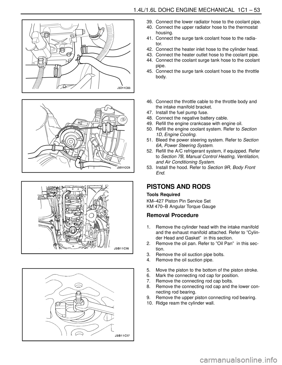
39. Connect the lower radiator hose to the coolant pipe.
40. Connect the upper radiator hose to the thermostat
housing.
41. Connect the surge tank coolant hose to the radia-
tor.
42. Connect the heater inlet hose to the cylinder head.
43. Connect the heater outlet hose to the coolant pipe.
44. Connect the coolant surge tank hose to the coolant
pipe.
45. Connect the surge tank coolant hose to the throttle
body.
46. Connect the throttle cable to the throttle body and
the intake manifold bracket.
47. Install the fuel pump fuse.
48. Connect the negative battery cable.
49. Refill the engine crankcase with engine oil.
50. Refill the engine coolant system. Refer to Section
1D, Engine Cooling.
51. Bleed the power steering system. Refer to Section
6A, Power Steering System.
52. Refill the A/C refrigerant system, if equipped. Refer
to Section 7B, Manual Control Heating, Ventilation,
and Air Conditioning System.
53. Install the hood. Refer to Section 9R, Body Front
End.
PISTONS AND RODS
Tools Required
KM–427 Piston Pin Service Set
KM 470–B Angular Torque Gauge
Removal Procedure
1. Remove the cylinder head with the intake manifold
and the exhaust manifold attached. Refer to ”Cylin-
der Head and Gasket” in this section.
2. Remove the oil pan. Refer to ”Oil Pan” in this sec-
tion.
3. Remove the oil suction pipe bolts.
4. Remove the oil suction pipe.
5. Move the piston to the bottom of the piston stroke.
6. Mark the connecting rod cap for position.
7. Remove the connecting rod cap bolts.
8. Remove the connecting rod cap and the lower con-
necting rod bearing.
9. Remove the upper piston connecting rod bearing.
10. Ridge ream the cylinder wall.
Page 99 of 2643
1C1 – 56I1.4L/1.6L DOHC ENGINE MECHANICAL
DAEWOO V–121 BL4
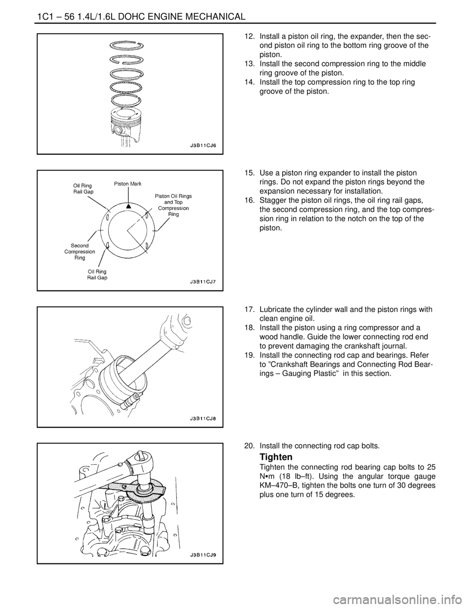
12. Install a piston oil ring, the expander, then the sec-
ond piston oil ring to the bottom ring groove of the
piston.
13. Install the second compression ring to the middle
ring groove of the piston.
14. Install the top compression ring to the top ring
groove of the piston.
15. Use a piston ring expander to install the piston
rings. Do not expand the piston rings beyond the
expansion necessary for installation.
16. Stagger the piston oil rings, the oil ring rail gaps,
the second compression ring, and the top compres-
sion ring in relation to the notch on the top of the
piston.
17. Lubricate the cylinder wall and the piston rings with
clean engine oil.
18. Install the piston using a ring compressor and a
wood handle. Guide the lower connecting rod end
to prevent damaging the crankshaft journal.
19. Install the connecting rod cap and bearings. Refer
to ”Crankshaft Bearings and Connecting Rod Bear-
ings – Gauging Plastic” in this section.
20. Install the connecting rod cap bolts.
Tighten
Tighten the connecting rod bearing cap bolts to 25
NSm (18 lb–ft). Using the angular torque gauge
KM–470–B, tighten the bolts one turn of 30 degrees
plus one turn of 15 degrees.
Page 108 of 2643
1.4L/1.6L DOHC ENGINE MECHANICAL 1C1 – 65
DAEWOO V–121 BL4
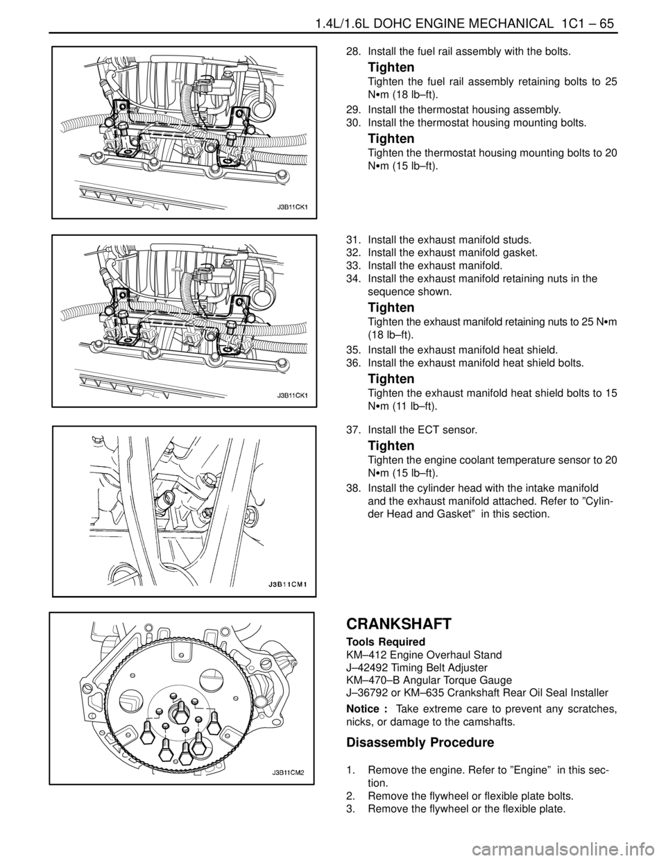
28. Install the fuel rail assembly with the bolts.
Tighten
Tighten the fuel rail assembly retaining bolts to 25
NSm (18 lb–ft).
29. Install the thermostat housing assembly.
30. Install the thermostat housing mounting bolts.
Tighten
Tighten the thermostat housing mounting bolts to 20
NSm (15 lb–ft).
31. Install the exhaust manifold studs.
32. Install the exhaust manifold gasket.
33. Install the exhaust manifold.
34. Install the exhaust manifold retaining nuts in the
sequence shown.
Tighten
Tighten the exhaust manifold retaining nuts to 25 NSm
(18 lb–ft).
35. Install the exhaust manifold heat shield.
36. Install the exhaust manifold heat shield bolts.
Tighten
Tighten the exhaust manifold heat shield bolts to 15
NSm (11 lb–ft).
37. Install the ECT sensor.
Tighten
Tighten the engine coolant temperature sensor to 20
NSm (15 lb–ft).
38. Install the cylinder head with the intake manifold
and the exhaust manifold attached. Refer to ”Cylin-
der Head and Gasket” in this section.
CRANKSHAFT
Tools Required
KM–412 Engine Overhaul Stand
J–42492 Timing Belt Adjuster
KM–470–B Angular Torque Gauge
J–36792 or KM–635 Crankshaft Rear Oil Seal Installer
Notice : Take extreme care to prevent any scratches,
nicks, or damage to the camshafts.
Disassembly Procedure
1. Remove the engine. Refer to ”Engine” in this sec-
tion.
2. Remove the flywheel or flexible plate bolts.
3. Remove the flywheel or the flexible plate.
Page 113 of 2643
1C1 – 70I1.4L/1.6L DOHC ENGINE MECHANICAL
DAEWOO V–121 BL4
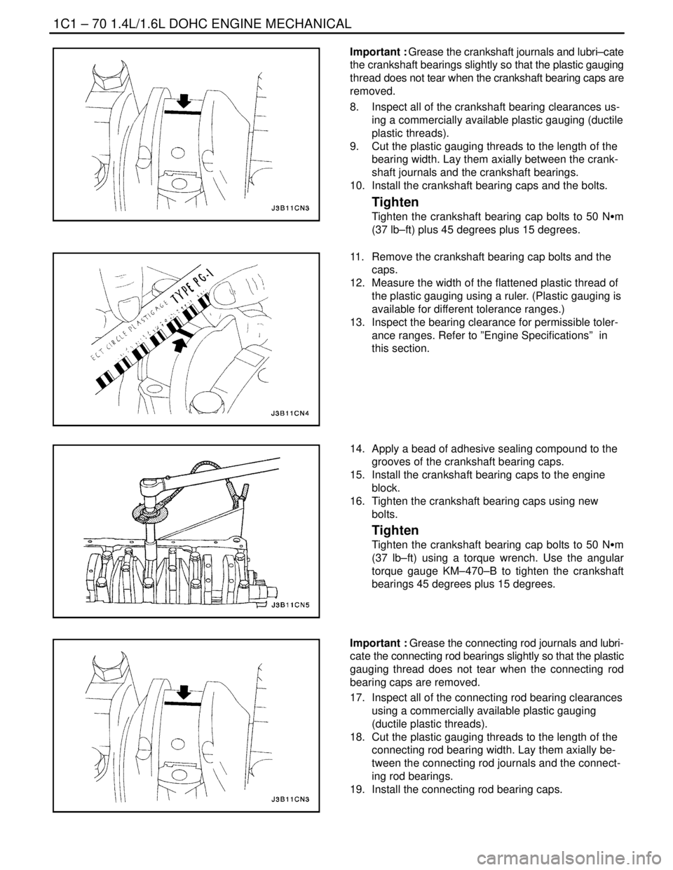
Important : Grease the crankshaft journals and lubri–cate
the crankshaft bearings slightly so that the plastic gauging
thread does not tear when the crankshaft bearing caps are
removed.
8. Inspect all of the crankshaft bearing clearances us-
ing a commercially available plastic gauging (ductile
plastic threads).
9. Cut the plastic gauging threads to the length of the
bearing width. Lay them axially between the crank-
shaft journals and the crankshaft bearings.
10. Install the crankshaft bearing caps and the bolts.
Tighten
Tighten the crankshaft bearing cap bolts to 50 NSm
(37 lb–ft) plus 45 degrees plus 15 degrees.
11. Remove the crankshaft bearing cap bolts and the
caps.
12. Measure the width of the flattened plastic thread of
the plastic gauging using a ruler. (Plastic gauging is
available for different tolerance ranges.)
13. Inspect the bearing clearance for permissible toler-
ance ranges. Refer to ”Engine Specifications” in
this section.
14. Apply a bead of adhesive sealing compound to the
grooves of the crankshaft bearing caps.
15. Install the crankshaft bearing caps to the engine
block.
16. Tighten the crankshaft bearing caps using new
bolts.
Tighten
Tighten the crankshaft bearing cap bolts to 50 NSm
(37 lb–ft) using a torque wrench. Use the angular
torque gauge KM–470–B to tighten the crankshaft
bearings 45 degrees plus 15 degrees.
Important : Grease the connecting rod journals and lubri-
cate the connecting rod bearings slightly so that the plastic
gauging thread does not tear when the connecting rod
bearing caps are removed.
17. Inspect all of the connecting rod bearing clearances
using a commercially available plastic gauging
(ductile plastic threads).
18. Cut the plastic gauging threads to the length of the
connecting rod bearing width. Lay them axially be-
tween the connecting rod journals and the connect-
ing rod bearings.
19. Install the connecting rod bearing caps.
Page 114 of 2643
1.4L/1.6L DOHC ENGINE MECHANICAL 1C1 – 71
DAEWOO V–121 BL4
Tighten
Tighten the connecting rod bearing cap bolts to 25
NSm (18 lb–ft) using a torque wrench. Use the angular
torque gauge KM–470–B to tighten the connecting
rod bearing cap bolts 30 degrees plus 15 degrees.
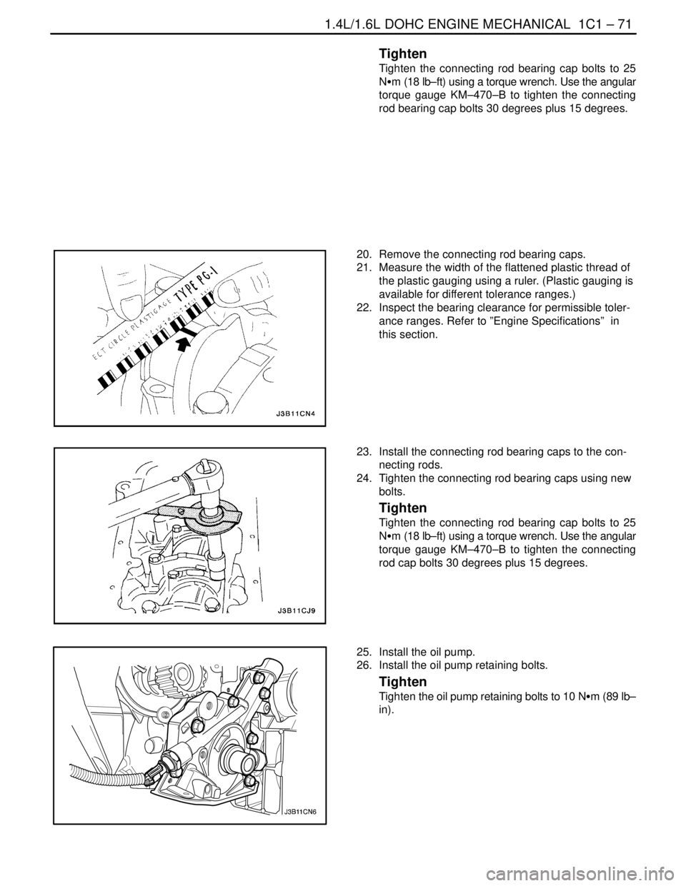
20. Remove the connecting rod bearing caps.
21. Measure the width of the flattened plastic thread of
the plastic gauging using a ruler. (Plastic gauging is
available for different tolerance ranges.)
22. Inspect the bearing clearance for permissible toler-
ance ranges. Refer to ”Engine Specifications” in
this section.
23. Install the connecting rod bearing caps to the con-
necting rods.
24. Tighten the connecting rod bearing caps using new
bolts.
Tighten
Tighten the connecting rod bearing cap bolts to 25
NSm (18 lb–ft) using a torque wrench. Use the angular
torque gauge KM–470–B to tighten the connecting
rod cap bolts 30 degrees plus 15 degrees.
25. Install the oil pump.
26. Install the oil pump retaining bolts.
Tighten
Tighten the oil pump retaining bolts to 10 NSm (89 lb–
in).
Page 117 of 2643
1C1 – 74I1.4L/1.6L DOHC ENGINE MECHANICAL
DAEWOO V–121 BL4
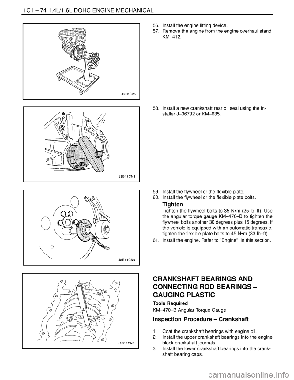
56. Install the engine lifting device.
57. Remove the engine from the engine overhaul stand
KM–412.
58. Install a new crankshaft rear oil seal using the in-
staller J–36792 or KM–635.
59. Install the flywheel or the flexible plate.
60. Install the flywheel or the flexible plate bolts.
Tighten
Tighten the flywheel bolts to 35 NSm (25 lb–ft). Use
the angular torque gauge KM–470–B to tighten the
flywheel bolts another 30 degrees plus 15 degrees. If
the vehicle is equipped with an automatic transaxle,
tighten the flexible plate bolts to 45 NSm (33 lb–ft).
61. Install the engine. Refer to ”Engine” in this section.
CRANKSHAFT BEARINGS AND
CONNECTING ROD BEARINGS –
GAUGING PLASTIC
Tools Required
KM–470–B Angular Torque Gauge
Inspection Procedure – Crankshaft
1. Coat the crankshaft bearings with engine oil.
2. Install the upper crankshaft bearings into the engine
block crankshaft journals.
3. Install the lower crankshaft bearings into the crank-
shaft bearing caps.
Page 118 of 2643
1.4L/1.6L DOHC ENGINE MECHANICAL 1C1 – 75
DAEWOO V–121 BL4
4. Install the crankshaft.
5. Inspect the crankshaft end play with the crankshaft
bearings installed.
6. Check for permissible crankshaft end play. Refer to
”Engine Specifications” in this section.
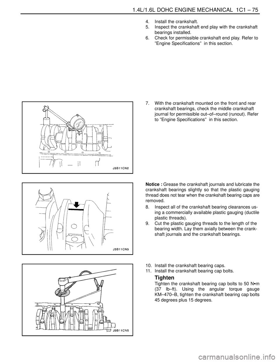
7. With the crankshaft mounted on the front and rear
crankshaft bearings, check the middle crankshaft
journal for permissible out–of–round (runout). Refer
to ”Engine Specifications” in this section.
Notice : Grease the crankshaft journals and lubricate the
crankshaft bearings slightly so that the plastic gauging
thread does not tear when the crankshaft bearing caps are
removed.
8. Inspect all of the crankshaft bearing clearances us-
ing a commercially available plastic gauging (ductile
plastic threads).
9. Cut the plastic gauging threads to the length of the
bearing width. Lay them axially between the crank-
shaft journals and the crankshaft bearings.
10. Install the crankshaft bearing caps.
11. Install the crankshaft bearing cap bolts.
Tighten
Tighten the crankshaft bearing cap bolts to 50 NSm
(37 lb–ft). Using the angular torque gauge
KM–470–B, tighten the crankshaft bearing cap bolts
45 degrees plus 15 degrees.