Page 256 of 2643

1F – 10IENGINE CONTROLS
DAEWOO V–121 BL4
FASTENER TIGHTENING SPECIFICATIONS
ApplicationNSmLb–FtLb–In
Camshaft Position Sensor Bolts (1.4L/1.6L DOHC)7–62
Camshaft Position Sensor Bolts (1.8 DOHC)8–71
Crankshaft Position Sensor Retaining Bolt (1.4L/1.6L DOHC)6.5–58
Crankshaft Position Sensor Retaining Bolt (1.8 DOHC)8–71
Electronic Ignition System Ignition Coil Retaining Bolts10–89
Exhaust Gas Recirculation Valve Retaining Bolts3022–
Engine Control Module Bolts12–106
Engine Coolant Temperature Sensor Bolt (1.4L/1.6L DOHC)17.513–
Engine Coolant Temperature Sensor Bolt (1.8 DOHC)2015–
Evaporative Emission Canister Flange Bolt4–35
Evaporative Emission Canister Purge Solenoid Bracket Bolt5–44
Fuel Filter Mounting Bracket Assembly Bolt4–35
Fuel Tank Retaining Bolts2015–
Fuel Rail Retaining Bolts2518–
Idle Air Control Valve Retaining Bolts (1.8 DOHC)3–27
Intake Air Temperature Sensor2216–
Knock Sensor Bolt2015–
Manifold Absolute Pressure Sensor Bolts (1.4L/1.6L DOHC)8–71
Manifold Absolute Pressure Sensor Bolts (1.8 DOHC)4–35
Oxygen Sensor Bolt4231–
Throttle Body Retaining Nuts (1.4L/1.6L DOHC)1511–
Throttle Body Retaining Nuts (1.8 DOHC)10–89
Throttle Position Sensor Retaining Bolts (1.8 DOHC)2–18
Page 272 of 2643
1F – 26IENGINE CONTROLS
DAEWOO V–121 BL4
T3B11F15
Front Heated Oxygen Sensor
(HO2S1) Connector
234 1
T3D11F47
EVAP Canister
Purge Solenoid
Connector
12
Page 274 of 2643

1F – 28IENGINE CONTROLS
DAEWOO V–121 BL4
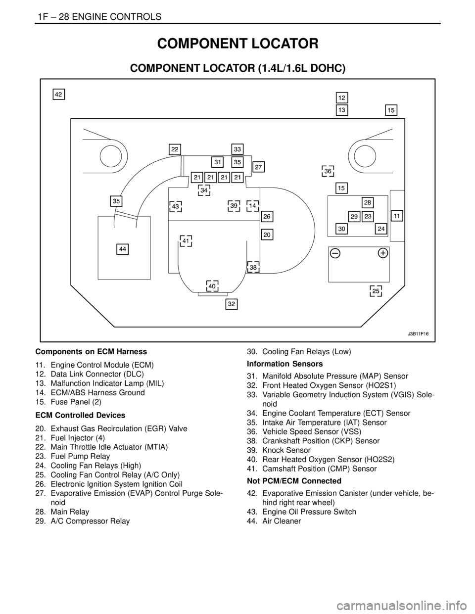
COMPONENT LOCATOR
COMPONENT LOCATOR (1.4L/1.6L DOHC)
Components on ECM Harness
11. Engine Control Module (ECM)
12. Data Link Connector (DLC)
13. Malfunction Indicator Lamp (MIL)
14. ECM/ABS Harness Ground
15. Fuse Panel (2)
ECM Controlled Devices
20. Exhaust Gas Recirculation (EGR) Valve
21. Fuel Injector (4)
22. Main Throttle Idle Actuator (MTIA)
23. Fuel Pump Relay
24. Cooling Fan Relays (High)
25. Cooling Fan Control Relay (A/C Only)
26. Electronic Ignition System Ignition Coil
27. Evaporative Emission (EVAP) Control Purge Sole-
noid
28. Main Relay
29. A/C Compressor Relay30. Cooling Fan Relays (Low)
Information Sensors
31. Manifold Absolute Pressure (MAP) Sensor
32. Front Heated Oxygen Sensor (HO2S1)
33. Variable Geometry Induction System (VGIS) Sole-
noid
34. Engine Coolant Temperature (ECT) Sensor
35. Intake Air Temperature (IAT) Sensor
36. Vehicle Speed Sensor (VSS)
38. Crankshaft Position (CKP) Sensor
39. Knock Sensor
40. Rear Heated Oxygen Sensor (HO2S2)
41. Camshaft Position (CMP) Sensor
Not PCM/ECM Connected
42. Evaporative Emission Canister (under vehicle, be-
hind right rear wheel)
43. Engine Oil Pressure Switch
44. Air Cleaner
Page 275 of 2643

ENGINE CONTROLS 1F – 29
DAEWOO V–121 BL4
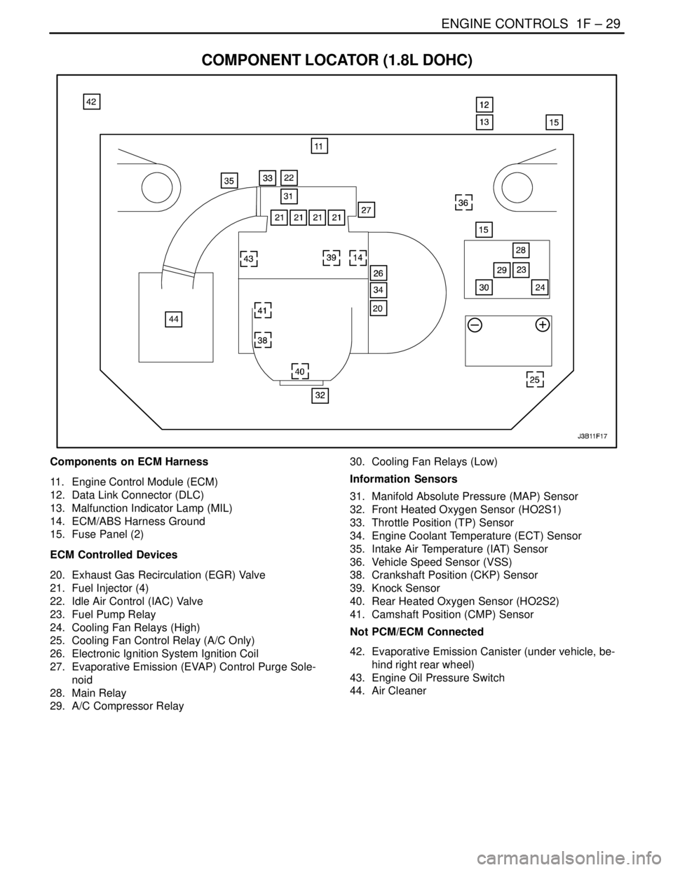
COMPONENT LOCATOR (1.8L DOHC)
Components on ECM Harness
11. Engine Control Module (ECM)
12. Data Link Connector (DLC)
13. Malfunction Indicator Lamp (MIL)
14. ECM/ABS Harness Ground
15. Fuse Panel (2)
ECM Controlled Devices
20. Exhaust Gas Recirculation (EGR) Valve
21. Fuel Injector (4)
22. Idle Air Control (IAC) Valve
23. Fuel Pump Relay
24. Cooling Fan Relays (High)
25. Cooling Fan Control Relay (A/C Only)
26. Electronic Ignition System Ignition Coil
27. Evaporative Emission (EVAP) Control Purge Sole-
noid
28. Main Relay
29. A/C Compressor Relay30. Cooling Fan Relays (Low)
Information Sensors
31. Manifold Absolute Pressure (MAP) Sensor
32. Front Heated Oxygen Sensor (HO2S1)
33. Throttle Position (TP) Sensor
34. Engine Coolant Temperature (ECT) Sensor
35. Intake Air Temperature (IAT) Sensor
36. Vehicle Speed Sensor (VSS)
38. Crankshaft Position (CKP) Sensor
39. Knock Sensor
40. Rear Heated Oxygen Sensor (HO2S2)
41. Camshaft Position (CMP) Sensor
Not PCM/ECM Connected
42. Evaporative Emission Canister (under vehicle, be-
hind right rear wheel)
43. Engine Oil Pressure Switch
44. Air Cleaner
Page 317 of 2643

ENGINE CONTROLS 1F – 71
DAEWOO V–121 BL4
MAIN RELAY CIRCUIT CHECK (1.4L/1.6L DOHC)
Circuit Description
When the ignition is turned On or to the START position,
the main relay is energized. The main relay then supply
voltage to the engine fuse block fuse Ef11. The Electronic
Ignition (EI) system ignition coil, Evaporative Emission
(EVAP) Canister Purge Solenoid and Heated Oxygen
Sensor (HO2S) are supplied voltage through the engine
fuse block fuse Ef11. The fuel injectors are supplied volt-
age through the engine fuse block fuse Ef11.Diagnostic Aids
S An intermittent problem may be caused by a poor
connection, rubbed through wire insulation, or a
broken wire inside the insulation.
S A fault main relay will cause a no start condition.
There will be no voltage supplied to the EI system
ignition coil, or the fuel injectors. Without voltage
supplied to these components, they will not oper-
ate.
Main Relay Circuit Check (1.4L/1.6L DOHC)
StepActionValue(s)YesNo
11. Turn the ignition OFF.
2. Disconnect the engine fuse block fuse Ef11.
3. Turn the ignition ON.
4. With a test light connected to the ground,
probe the fuse terminals nearest the main relay
for fuse Ef11.
Is the light on at both terminal?–System OKGo to Step 2
2Is the light on at only one terminal?–Go to Step 3Go to Step 4
3Repair the open in the wiring between the main relay
connector terminal 87 and the fuse Ef11.
Is the repair complete?–System OK–
Page 319 of 2643

ENGINE CONTROLS 1F – 73
DAEWOO V–121 BL4
MAIN RELAY CIRCUIT CHECK (1.8L DOHC)
Circuit Description
When the ignition is turned On or to the START position,
the main relay is energized. The main relay then supply
voltage to the engine fuse block fuse F2. The Electronic
Ignition (EI) system ignition coil, Evaporative Emission
(EVAP) Canister Purge Solenoid and Heated Oxygen
Sensor (HO2S) are supplied voltage through the engine
fuse block fuse F2. The fuel injectors are supplied voltage
through the engine fuse block fuse F2.Diagnostic Aids
S An intermittent problem may be caused by a poor
connection, rubbed through wire insulation, or a
broken wire inside the insulation.
S A fault main relay will cause a no start condition.
There will be no voltage supplied to the EI system
ignition coil, or the fuel injectors. Without voltage
supplied to these components, they will not oper-
ate.
Main Relay Circuit Check (1.8L DOHC)
StepActionValue(s)YesNo
11. Turn the ignition OFF.
2. Disconnect the I/P fuse block fuse F2.
3. Turn the ignition ON.
4. With a test light connected to the ground,
probe the fuse terminals nearest the ignition
relay for fuse F2.
Is the light on at both terminal?–System OKGo to Step 2
2Is the light on at only one terminal?–Go to Step 3Go to Step 4
3Repair the open in the wiring between the ignition
relay connector terminal 87 and the fuse F2.
Is the repair complete?–System OK–
Page 357 of 2643

ENGINE CONTROLS 1F – 111
DAEWOO V–121 BL4
TROUBLE CODE DIAGNOSIS
(1.4L/1.6L DOHC)
CLEARING TROUBLE CODES
Notice : To prevent Engine Control Module (ECM) dam-
age, the key must be OFF when disconnecting or recon-
necting the power to the ECM (for example battery cable,
ECM pigtail connector, ECM fuse, jumper cables,
etc.).When the ECM sets a Diagnostic Trouble Code
(DTC), the Malfunction Indicator Lamp (MIL) lamp will be
turned on only for type A, B and E but a DTC will be stored
in the ECM’s memory for all types of DTC. If the problemis intermittent, the MIL will go out after 10 seconds if the
fault is no longer present. The DTC will stay in the ECM’s
memory until cleared by scan tool. Removing battery volt-
age for 10 seconds will clear some stored DTCs.
DTCs should be cleared after repairs have been com-
pleted. Some diagnostic tables will tell you to clear the
codes before using the chart. This allows the ECM to set
the DTC while going through the chart, which will help to
find the cause of the problem more quickly.
DIAGNOSTIC TROUBLE CODES (1.4L/1.6L DOHC)
DTCFunctionError
TypeIlluminate MIL
P0107Manifold Absolute Pressure Sensor Low VoltageAYES
P0108Manifold Absolute Pressure Sensor High VoltageAYES
P0112Intake Air Temperature Sensor Low VoltageEYES
P0113Intake Air Temperature Sensor High VoltageEYES
P0117Engine Coolant Temperature Sensor Low VoltageAYES
P0118Engine Coolant Temperature Sensor High VoltageAYES
P0122Throttle Position Sensor Low VoltageAYES
P0123Throttle Position Sensor High VoltageAYES
P0131Front Heated Oxygen Sensor Low VoltageAYES
P0132Front Heated Oxygen Sensor High VoltageAYES
P0133Front Heated Oxygen Sensor No ActivityEYES
P0135Front Heated Oxygen Sensor Heater Circuit Not FunctioningEYES
P0137Rear Heated Oxygen Sensor Low VoltageEYES
P0138Rear Heated Oxygen Sensor High VoltageEYES
P0140Rear Heated Oxygen Sensor No ActivityEYES
P0141Rear Heated Oxygen Sensor Heater MalfuctionEYES
P0171Fuel Trim System Too LeanEYES
P0172Fuel Trim System Too RichEYES
P0222Main Throttle Idle Actuactor (MTIA) Low VoltageAYES
P0223Main Throttle Idle Actuactor (MTIA) High VoltageAYES
P0261Injector 1 Low VoltageAYES
P0262Injector 1 High VoltageAYES
P0264Injector 2 Low VoltageAYES
P0265Injector 2 High VoltageAYES
P0267Injector 3 Low VoltageAYES
P0268Injector 3 High VoltageAYES
P0270Injector 4 Low VoltageAYES
P0271Injector 4 High VoltageAYES
P0300Multiple Cylinder Misfire (Catalyst Damage)ABLINKING
Page 383 of 2643

ENGINE CONTROLS 1F – 137
DAEWOO V–121 BL4
DIAGNOSTIC TROUBLE CODE (DTC) P0131
FRONT HEATED OXYGEN SENSOR LOW VOLTAGE
Circuit Description
The engine control module (ECM) supplies a voltage of
about 450mm volts between the ECM terminals 44 and 13.
The oxygen (O2) sensor varies the voltage within a range
of about 1volt if the exhaust is rich, down to about 100mm
volts if the exhaust is lean. The O2 sensor is like an open
circuit and produces no voltage when it is below
360°C(600°F). An open O2 sensor circuit or a cold O2
sensor causes ”open loop” operation.
Conditions for Setting the DTC
(Case A)
S The engine controls system is in closed loop.
S Engine speed is less than 6,000rpm.
S The oxygen sensor voltage is below 0.07V for at
least 40seconds.
S DTCs P0107, P0108, P0117, P0118, P0122,
P0123, P0335, P0336, P0341, P0342, P0400,
P0404, P0405, P0406 are NOT SET.
(Case B)
S The engine controls system is in closed loop.
S Engine speed is less than 6,000rpm.
S The oxygen sensor voltage is between 0.352 and
0.499 at least 10 seconds.Action Taken When the DTC Sets
S The Malfunction Indicator Lamp (MIL) will illumi-
nate.
S The ECM will record operating conditions at the
time the diagnostic fails. This information will be
stored in the Freeze Frame and Failure Records
buffers.
S A history DTC is stored.
S The coolant fan turns ON.
Conditions for Clearing the MIL/DTC
S The MIL will turn off after four consecutive ignition
cycles in which the diagnostic runs without a fault.
S A history DTC will clear after 40 consecutive warm–
up cycles without a fault.
S DTC(s) can be cleared by using the scan tool.
S Disconnecting the ECM battery feed for more than
10 seconds.
Diagnostic Aids
Normal scan tool voltage varies between 0.1volts and 0.9
volts while in closed loop.
Inspect the oxygen (O2) sensor wire. The O2 sensor may
be positioned incorrectly and contacting the exhaust man-
ifold.