2004 DAEWOO LACETTI wheel
[x] Cancel search: wheelPage 1932 of 2643
POWER STEERING GEAR 6C – 15
DAEWOO V–121 BL4
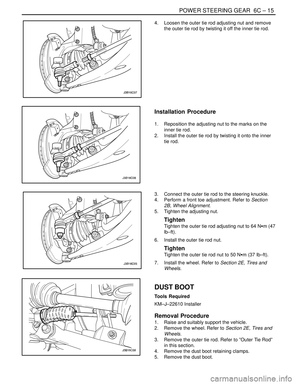
4. Loosen the outer tie rod adjusting nut and remove
the outer tie rod by twisting it off the inner tie rod.
Installation Procedure
1. Reposition the adjusting nut to the marks on the
inner tie rod.
2. Install the outer tie rod by twisting it onto the inner
tie rod.
3. Connect the outer tie rod to the steering knuckle.
4. Perform a front toe adjustment. Refer to Section
2B, Wheel Alignment.
5. Tighten the adjusting nut.
Tighten
Tighten the outer tie rod adjusting nut to 64 NSm (47
lb–ft).
6. Install the outer tie rod nut.
Tighten
Tighten the outer tie rod nut to 50 NSm (37 lb–ft).
7. Install the wheel. Refer to Section 2E, Tires and
Wheels.
DUST BOOT
Tools Required
KM–J–22610 Installer
Removal Procedure
1. Raise and suitably support the vehicle.
2. Remove the wheel. Refer to Section 2E, Tires and
Wheels.
3. Remove the outer tie rod. Refer to ”Outer Tie Rod”
in this section.
4. Remove the dust boot retaining clamps.
5. Remove the dust boot.
Page 1933 of 2643
6C – 16IPOWER STEERING GEAR
DAEWOO V–121 BL4
Installation Procedure
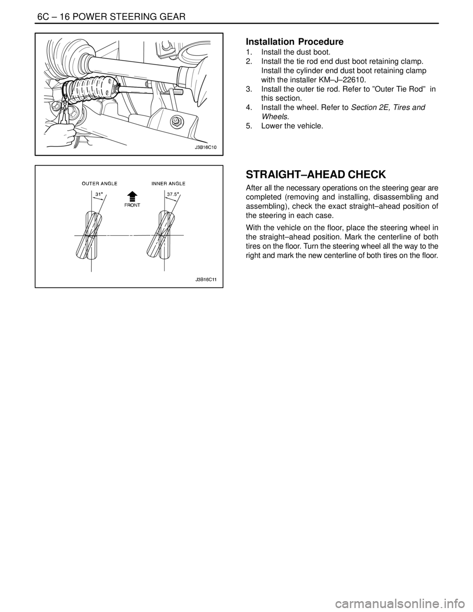
1. Install the dust boot.
2. Install the tie rod end dust boot retaining clamp.
Install the cylinder end dust boot retaining clamp
with the installer KM–J–22610.
3. Install the outer tie rod. Refer to ”Outer Tie Rod” in
this section.
4. Install the wheel. Refer to Section 2E, Tires and
Wheels.
5. Lower the vehicle.
STRAIGHT–AHEAD CHECK
After all the necessary operations on the steering gear are
completed (removing and installing, disassembling and
assembling), check the exact straight–ahead position of
the steering in each case.
With the vehicle on the floor, place the steering wheel in
the straight–ahead position. Mark the centerline of both
tires on the floor. Turn the steering wheel all the way to the
right and mark the new centerline of both tires on the floor.
Page 1934 of 2643
POWER STEERING GEAR 6C – 17
DAEWOO V–121 BL4
Straight–Ahead Check Table
StepActionValue(s)YesNo
1Place the steering wheel in the straight–
ahead position.
Is the wheel in the correct position?–Go to
Step 2–
2Is the lower intermediate shaft pinch bolt lying
parallel to the steering gear?–Go to
Step 3Go to
Step 4
3Is the steering wheel off center by more than
5 degrees?–Go to
Step 5Go to
Step 6
4The pinion is displaced on the rack. The steer-
ing pinion position must be corrected.
Is the repair complete?–Go to
Step 2–
5Remove steering wheel and center on the
spindle splines.
Is the repair complete?–Go to
Step 3–
6Turn the steering wheel all the way to the
right. Measure the inner and the outer angles
of the tire centerline compared to the straight–
ahead centerline. Are the angles within speci-
fications?Inner
angle:
37.5°
Outer
angle: 31°System
OKGo to
Step 7
7The rack assembly was not assembled cor-
rectly.
Repair as needed.
Is the repair complete?–Go to
Step 6–
INTERMEDIATE SHAFT AND DASH
SEAL
(Left–Hand Drive Shown, Right–Hand
Drive Similar)
Removal Procedure
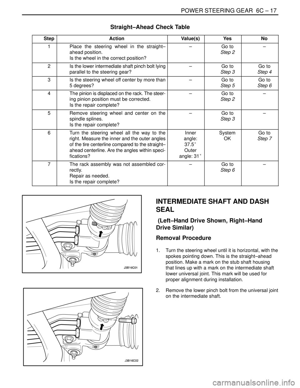
1. Turn the steering wheel until it is horizontal, with the
spokes pointing down. This is the straight–ahead
position. Make a mark on the stub shaft housing
that lines up with a mark on the intermediate shaft
lower universal joint. This mark will be used for
proper alignment during installation.
2. Remove the lower pinch bolt from the universal joint
on the intermediate shaft.
Page 1935 of 2643
6C – 18IPOWER STEERING GEAR
DAEWOO V–121 BL4
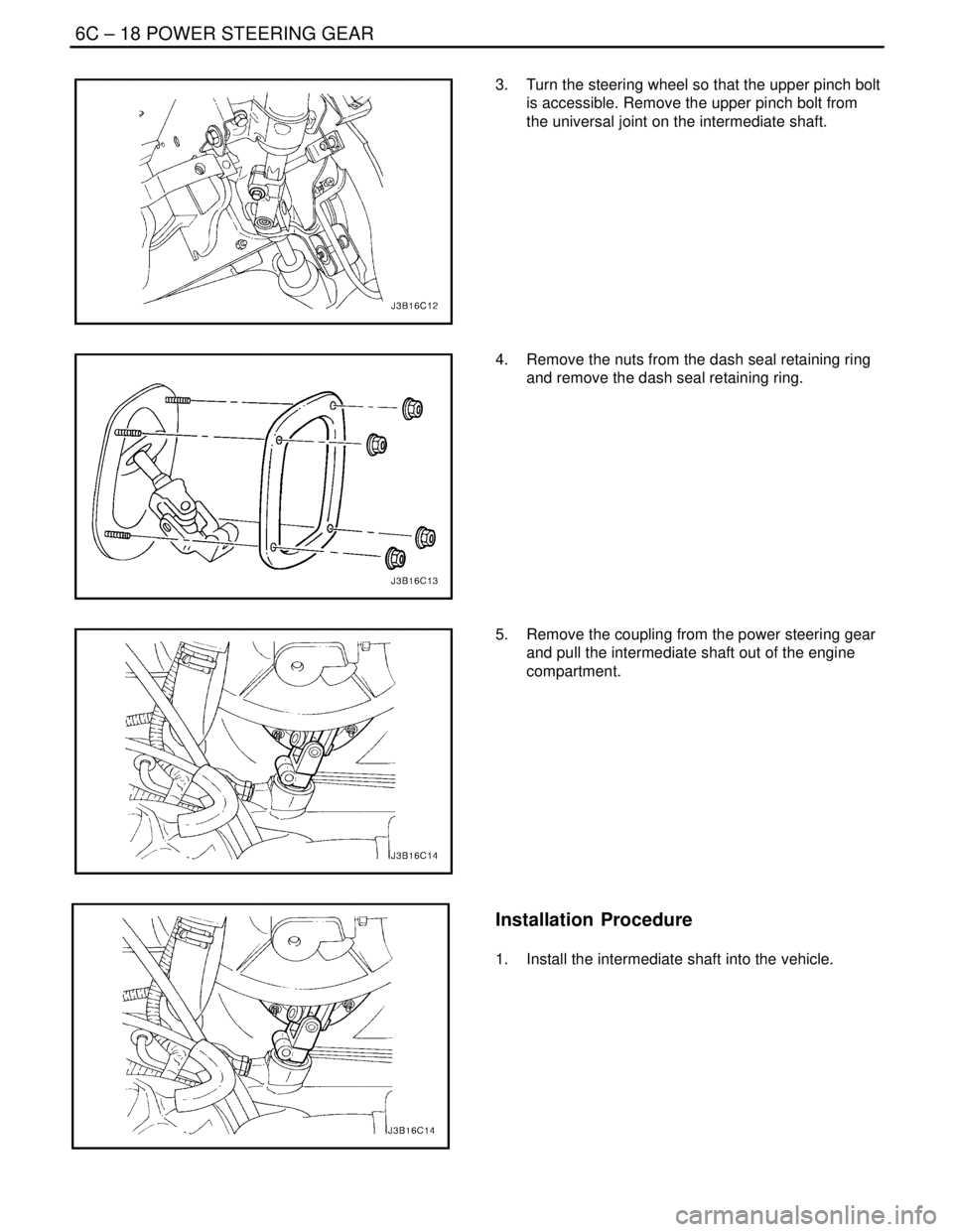
3. Turn the steering wheel so that the upper pinch bolt
is accessible. Remove the upper pinch bolt from
the universal joint on the intermediate shaft.
4. Remove the nuts from the dash seal retaining ring
and remove the dash seal retaining ring.
5. Remove the coupling from the power steering gear
and pull the intermediate shaft out of the engine
compartment.
Installation Procedure
1. Install the intermediate shaft into the vehicle.
Page 1936 of 2643
POWER STEERING GEAR 6C – 19
DAEWOO V–121 BL4
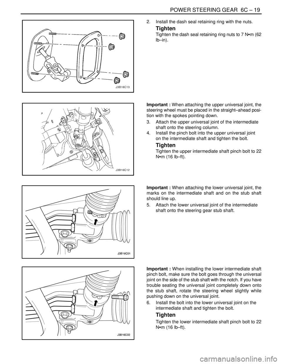
2. Install the dash seal retaining ring with the nuts.
Tighten
Tighten the dash seal retaining ring nuts to 7 NSm (62
lb–in).
Important : When attaching the upper universal joint, the
steering wheel must be placed in the straight–ahead posi-
tion with the spokes pointing down.
3. Attach the upper universal joint of the intermediate
shaft onto the steering column.
4. Install the pinch bolt into the upper universal joint
on the intermediate shaft and tighten the bolt.
Tighten
Tighten the upper intermediate shaft pinch bolt to 22
NSm (16 lb–ft).
Important : When attaching the lower universal joint, the
marks on the intermediate shaft and on the stub shaft
should line up.
5. Attach the lower universal joint of the intermediate
shaft onto the steering gear stub shaft.
Important : When installing the lower intermediate shaft
pinch bolt, make sure the bolt goes through the universal
joint on the side of the stub shaft with the notch. If you have
trouble seating the universal joint completely down onto
the stub shaft, rotate the steering wheel slightly while
pushing down on the universal joint.
6. Install the bolt into the lower universal joint on the
intermediate shaft and tighten the bolt.
Tighten
Tighten the lower intermediate shaft pinch bolt to 22
NSm (16 lb–ft).
Page 1942 of 2643
POWER STEERING GEAR 6C – 25
DAEWOO V–121 BL4
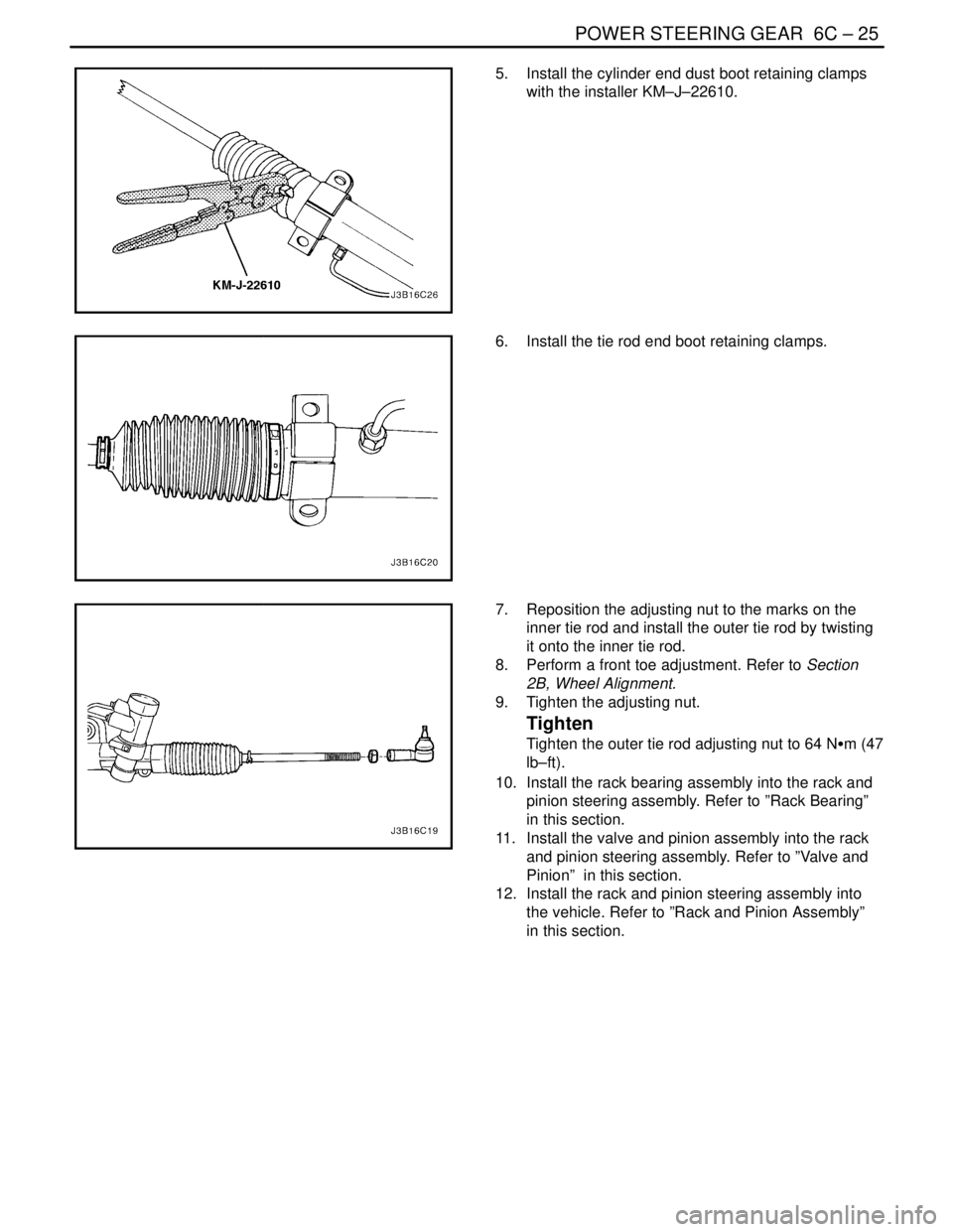
5. Install the cylinder end dust boot retaining clamps
with the installer KM–J–22610.
6. Install the tie rod end boot retaining clamps.
7. Reposition the adjusting nut to the marks on the
inner tie rod and install the outer tie rod by twisting
it onto the inner tie rod.
8. Perform a front toe adjustment. Refer to Section
2B, Wheel Alignment.
9. Tighten the adjusting nut.
Tighten
Tighten the outer tie rod adjusting nut to 64 NSm (47
lb–ft).
10. Install the rack bearing assembly into the rack and
pinion steering assembly. Refer to ”Rack Bearing”
in this section.
11. Install the valve and pinion assembly into the rack
and pinion steering assembly. Refer to ”Valve and
Pinion” in this section.
12. Install the rack and pinion steering assembly into
the vehicle. Refer to ”Rack and Pinion Assembly”
in this section.
Page 1947 of 2643
6C – 30IPOWER STEERING GEAR
DAEWOO V–121 BL4
RACK BEARING PRELOAD
ADJUSTMENT
Adjustment Procedure
1. Raise and suitably support the vehicle.
2. Center the steering wheel.
3. Remove the power steering gear. Refer to ”Rack
and Pinion Assembly” in this section.
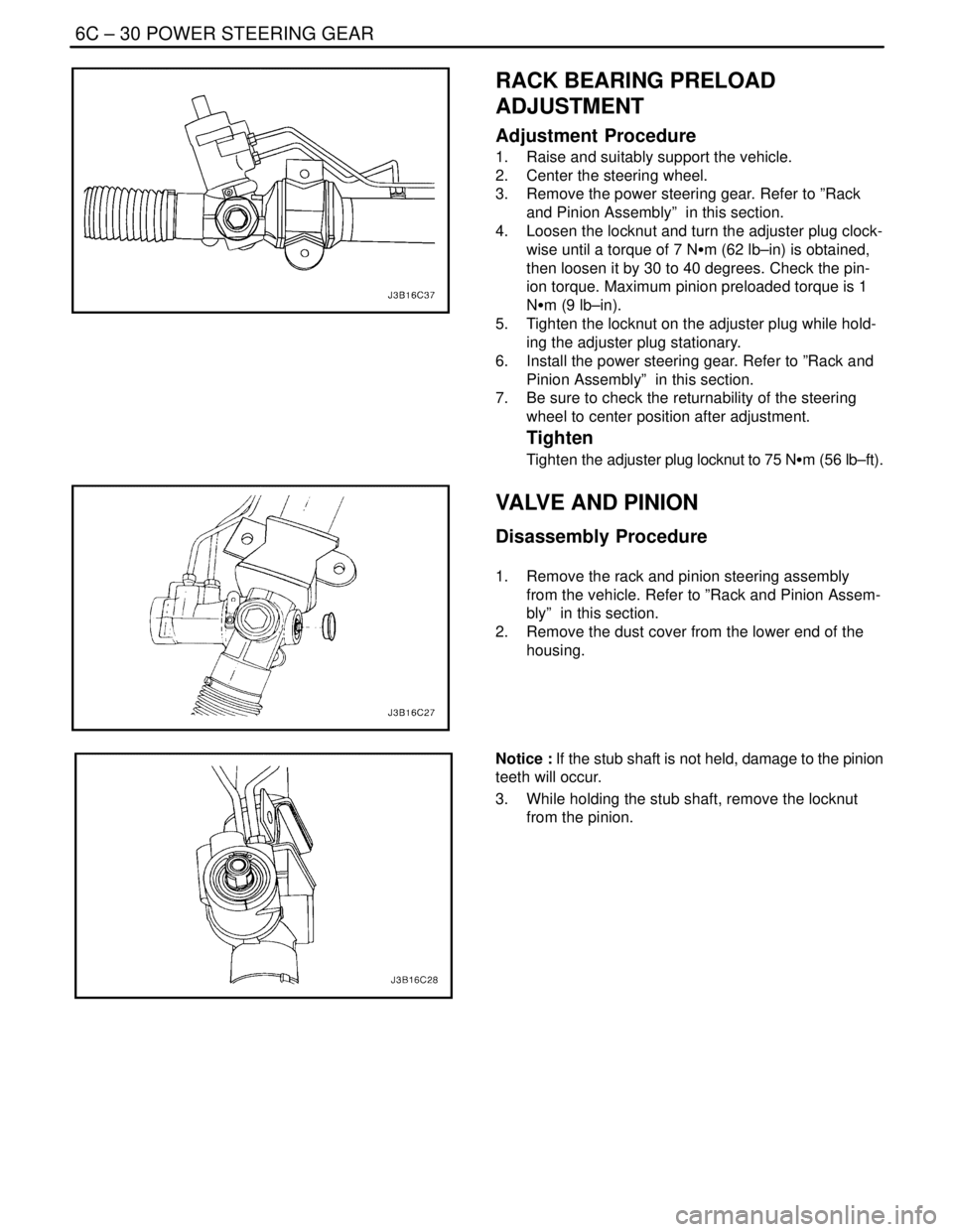
4. Loosen the locknut and turn the adjuster plug clock-
wise until a torque of 7 NSm (62 lb–in) is obtained,
then loosen it by 30 to 40 degrees. Check the pin-
ion torque. Maximum pinion preloaded torque is 1
NSm (9 lb–in).
5. Tighten the locknut on the adjuster plug while hold-
ing the adjuster plug stationary.
6. Install the power steering gear. Refer to ”Rack and
Pinion Assembly” in this section.
7. Be sure to check the returnability of the steering
wheel to center position after adjustment.
Tighten
Tighten the adjuster plug locknut to 75 NSm (56 lb–ft).
VALVE AND PINION
Disassembly Procedure
1. Remove the rack and pinion steering assembly
from the vehicle. Refer to ”Rack and Pinion Assem-
bly” in this section.
2. Remove the dust cover from the lower end of the
housing.
Notice : If the stub shaft is not held, damage to the pinion
teeth will occur.
3. While holding the stub shaft, remove the locknut
from the pinion.
Page 1950 of 2643

POWER STEERING GEAR 6C – 33
DAEWOO V–121 BL4
GENERAL DESCRIPTION
AND SYSTEM OPERATION
POWER RACK AND PINION
The power rack and pinion steering system has a rotary
control valve that directs hydraulic fluid coming from the
hydraulic pump to one side or the other side of the rack pis-
ton. The integral rack piston is attached to the rack. The
rack piston converts hydraulic pressure to a linear force
that moves the rack left or right. That force is then trans-
mitted through the tie rods to the steering knuckles, which
turn the wheels.
If power rack and pinion steering is not available, manual
rack and pinion control is used; however, with this system,
more steering effort is required. The movement of the
steering wheel is transferred to the pinion. The rotary
movement of the pinion is then transferred through the pin-
ion threads, which mesh with teeth on the rack, thereby
causing the rack to move in a linear direction.
A vane–type of hydraulic pump provides hydraulic pres-
sure for both steering systems.
SPEED SENSITIVE POWER
STEERING SYSTEM
The speed sensitive power steering (SSPS) system varies
the driver effort required to steer as the vehicle speed
changes. At low speeds, the system provides maximum
power assist for easy turning and parking maneuvers. At
higher speeds, the steering power is reduced to provide
the driver with firmer steering and directional stability. The
SSPS system accomplishes this by reducing the amount
of power steering fluid flow from the power steering pump
to the power steering gear as the vehicle speed increases.
When the vehicle is stationary, the SSPS system provides
maximum fluid flow to the steering gear. As the vehicle
speed increases, the fluid flow to the steering gear is de-
creased.
Control Module
The SSPS control module processes the vehicle speed in-
formation from the engine control module (ECM) and uses
the steering wheel rotation sensor to provide a control sig-
nal to the electronic variable orifice (EVO) actuator located
on the power steering pump.
Electronic Variable Orifice (EVO) Actuator
The electronic variable orifice (EVO) actuator is located on
the power steering pump and contains a solenoid– oper-
ated pintle valve. Fluid leaving the pump passes through
an orifice in the actuator tip. When the EVO actuator is
powered by the SSPS control module, the pintle moves
into the orifice and reduces the power steering fluid flow.As the vehicle speed increases, current from the SSPS
control module increases, and the pintle blocks more and
more of the orifice.
Steering Wheel Rotation Sensor
The steering wheel rotation sensor is located at the end of
the steering column housing and is used to send a signal
to the controller when abrupt or evasive steering maneu-
vers are needed.
Power Steering Pressure Hose
SSPS vehicles have a specific pressure hose assembly
which includes an in–line check valve in the rack and pin-
ion assembly. This reduces the amount of steering wheel
”kick” when driving over irregular road surfaces while oper-
ating at speeds with reduced flow rate and pressure.
Power Rack and Pinion
Except for differences in valve machining, the design of
the SSPS power rack and pinion assembly is the same as
for the a non–SSPS system. The steering wheel move-
ment is transferred to the pinion via the intermediate shaft.
The pinion moves the rack left or right through meshing the
pinion and the rack teeth. The force is then transmitted
through the tie rods and steering knuckle to steer the
wheels.
The power rack and pinion steering system has a rotary
control valve which directs the hydraulic fluid from the
power steering pump to one side or the other side of the
rack piston. The piston is attached to the rack and uses hy-
draulic pressure to move the rack left or right. The rotary
control valve regulates the degree of assist by responding
to the driver’s torque input.
If hydraulic assist is not available, manual control is main-
tained. However, under this condition, more steering effort
is required.
Power Steering Pump
The standard vane–type pump, which provides hydraulic
pressure for the system, incorporates a special discharge
fitting to hold the EVO actuator.
System Operation
System operation originates with input from the vehicle
speed sensor via the engine control module to the SSPS
control module. The SSPS control module sends a signal
to the SSPS actuator to vary the rate of fluid flow output
by the power steering pump.
Circuit Operation
The SSPS system uses inputs from the speed sensor and
steering wheel rotation sensor to the SSPS controller to
determine the desired amount of power steering assist.
The SSPS control module constantly compares the
amount of current flowing through the EVO actuator to the
desired current it has calculated. The EVO actuator has a
pintle that moves in and out of an orifice, regulating power