Page 1155 of 2643

PARKING BRAKE 4G – 3
DAEWOO V–121 BL4
7. Inspect and replace any parts of doubtful strength
or quality. This can be shown by discoloration from
heat or stress.
8. Using a vernier caliper, adjust the shoe assembly to
167.6 to 167.8 mm (6.60 to 6.61 inches) by turning
the adjuster nut clockwise to increase the diameter.
Measure the shoe assembly diameter as closely as
possible to the center of the lining material.
9. Inspect and install the rotors and calipers. Refer to
Section 4E1, Rear Disc Brakes.
10. Install the parking brake cable to the backplate le-
ver on each side of the vehicle.
11. In the vehicle cabin, pull on the parking brake han-
dle. Stop after hearing two clicks.
12. Turn the rear wheel by hand until the wheel begins
to drag.
13. Release the parking brake.
14. Turn the rear wheel by hand to check the drag. Re-
adjust the cable, if necessary.
15. Repeat the process for the other rear wheel.
16. Lower the vehicle.
PARKING BRAKE LEVER
Removal Procedure
1. Release the parking brake.
2. Remove the parking brake/gearshift console hood.
Refer to Section 9G, Interior Trim.
3. Measure the thread length from the end of the pull
rod to the hex nut.
4. Remove the hex nut.
5. Remove the parking brake warning lamp switch.
Notice : The parking brake switch should be replaced if
the BRAKE warning light in the instrument panel cluster
did not glow when the parking brake was applied with the
ignition switch ON.
Page 1161 of 2643
PARKING BRAKE 4G – 9
DAEWOO V–121 BL4
GENERAL DESCRIPTION
AND SYSTEM OPERATION
PARKING BRAKE
This braking system uses a BRAKE warning light located
in the instrument panel cluster. When the ignition switch
is in the START position, the BRAKE warning light shouldglow and go OFF when the the ignition switch returns to
the RUN position. Whenever the parking brake is applied
and the ignition switch is ON, the BRAKE warning light
should glow.
When the brake is firmly applied, the parking brake should
hold the vehicle with ample pedal travel remaining. Check
for frayed cables, rust, etc. or any condition that many in-
hibit present (or future) free movement of the parking
brake lever assembly.
Page 1165 of 2643
 & REVERSE LAMP CIRCUIT 5–102. . . . . . . . . . . .
1) MR–140/HV–240 : NOTCH BACK 5–102. . . . . . . . . .")
ELECTRICAL WIRING DIAGRAMSW5–5
14. STOP LAMP, CENTER HIGH MOUNT STOP LAMP (CHMSL) & REVERSE LAMP CIRCUIT 5–102. . . . . . . . . . . .
1) MR–140/HV–240 : NOTCH BACK 5–102. . . . . . . . . . . . . . . . . . . . . . . . . . . . . . . . . . . . . . . . . . . . . . . . . . . . . . . . . . . . .
2) MR–140/HV–240 : HATCH BACK 5–104. . . . . . . . . . . . . . . . . . . . . . . . . . . . . . . . . . . . . . . . . . . . . . . . . . . . . . . . . . . . .
3) SIRIUS D4 : NOTCH BACK5–106 . . . . . . . . . . . . . . . . . . . . . . . . . . . . . . . . . . . . . . . . . . . . . . . . . . . . . . . . . . . . . . . . . .
4) SIRIUS D4 : HATCH BACK5–108 . . . . . . . . . . . . . . . . . . . . . . . . . . . . . . . . . . . . . . . . . . . . . . . . . . . . . . . . . . . . . . . . . . .
15. TRUNK/TAIL GATE OPEN SWITCH, TRUNK LATCH SWITCH, TRUNK ROOM LAMP & HORN
CIRCUIT5–110 . . . . . . . . . . . . . . . . . . . . . . . . . . . . . . . . . . . . . . . . . . . . . . . . . . . . . . . . . . . . . . . . . . . . . . . . . . . . . . . . . . . . . . . . . .
1) DUAL HORN5–110 . . . . . . . . . . . . . . . . . . . . . . . . . . . . . . . . . . . . . . . . . . . . . . . . . . . . . . . . . . . . . . . . . . . . . . . . . . . . . . .
2) SIGNLE HORN5–112 . . . . . . . . . . . . . . . . . . . . . . . . . . . . . . . . . . . . . . . . . . . . . . . . . . . . . . . . . . . . . . . . . . . . . . . . . . . . .
16. LAMPS(MAP & ROOM) CIRCUIT5–114 . . . . . . . . . . . . . . . . . . . . . . . . . . . . . . . . . . . . . . . . . . . . . . . . . . . . . . . . . . . . . . . .
1) W/O SUN ROOF & W/ DECAY5–114 . . . . . . . . . . . . . . . . . . . . . . . . . . . . . . . . . . . . . . . . . . . . . . . . . . . . . . . . . . . . . . .
2) W/ SUN ROOF & W/ DECAY5–116 . . . . . . . . . . . . . . . . . . . . . . . . . . . . . . . . . . . . . . . . . . . . . . . . . . . . . . . . . . . . . . . . .
3) W/O SUN ROOF & W/O DECAY 5–118. . . . . . . . . . . . . . . . . . . . . . . . . . . . . . . . . . . . . . . . . . . . . . . . . . . . . . . . . . . . . .
4) W/ SUN ROOF & W/O DECAY5–120 . . . . . . . . . . . . . . . . . . . . . . . . . . . . . . . . . . . . . . . . . . . . . . . . . . . . . . . . . . . . . . .
17. CLOCK, CIGAR LIGHTER,ASHTRAY ILLUM. LAMP & EXTRA POWER JACK CIRCUIT 5–122. . . . . . . . . . . . . .
1) M/T5–122 . . . . . . . . . . . . . . . . . . . . . . . . . . . . . . . . . . . . . . . . . . . . . . . . . . . . . . . . . . . . . . . . . . . . . . . . . . . . . . . . . . . . . . .
2) A/T5–124 . . . . . . . . . . . . . . . . . . . . . . . . . . . . . . . . . . . . . . . . . . . . . . . . . . . . . . . . . . . . . . . . . . . . . . . . . . . . . . . . . . . . . . . .
18. CHIME BELL, SEAT BELT & KEY REMIND SWITCH CIRCUIT 5–126. . . . . . . . . . . . . . . . . . . . . . . . . . . . . . . . . . . . . .
19. WIPER CIRCUIT5–128 . . . . . . . . . . . . . . . . . . . . . . . . . . . . . . . . . . . . . . . . . . . . . . . . . . . . . . . . . . . . . . . . . . . . . . . . . . . . . . .
1) W/O RAIN SENSOR & AIR CONDITIONER : NOTCH BACK 5–128. . . . . . . . . . . . . . . . . . . . . . . . . . . . . . . . . . . . .
2) W/O RAIN SENSOR & AIR CONDITIONER : HATCH BACK 5–130. . . . . . . . . . . . . . . . . . . . . . . . . . . . . . . . . . . . . .
3) W/ RAIN SENSOR & AIR CONDITIONER : NOTCH BACK 5–132. . . . . . . . . . . . . . . . . . . . . . . . . . . . . . . . . . . . . . .
4) W/ RAIN SENSOR & AIR CONDITIONER : HATCH BACK 5–134. . . . . . . . . . . . . . . . . . . . . . . . . . . . . . . . . . . . . . .
5) W/O RAIN SENSOR & FATC : NOTCH BACK 5–136. . . . . . . . . . . . . . . . . . . . . . . . . . . . . . . . . . . . . . . . . . . . . . . . . .
6) W/O RAIN SENSOR & FATC : HATCH BACK 5–138. . . . . . . . . . . . . . . . . . . . . . . . . . . . . . . . . . . . . . . . . . . . . . . . . . .
7) W/ RAIN SENSOR & FATC : NOTCH BACK 5–140. . . . . . . . . . . . . . . . . . . . . . . . . . . . . . . . . . . . . . . . . . . . . . . . . . . .
8) W/ RAIN SENSOR & FATC : HATCH BACK 5–142. . . . . . . . . . . . . . . . . . . . . . . . . . . . . . . . . . . . . . . . . . . . . . . . . . . .
Page 1270 of 2643
5–110WELECTRICAL WIRING DIAGRAMS
15.TRUNK/TAIL GATE OPEN SWITCH, TRUNK LATCH SWITCH, TRUNK
ROOM LAMP & HORN CIRCUIT
1) DUAL HORN
a. CONNECTOR INFORMATION
CONNECTOR(NO.)
(PIN NO. COLOR)
CONNECTING, WIRING HARNESSCONNECTOR POSITION
C101 (21 Pin, White)Body � Engine Fuse BlockEngine Fuse Block
C102 (11 Pin, White)Body � Engine Fuse BlockEngine Fuse Block
C104 (24 Pin, White)Front � Engine Fuse BlockEngine Fuse Block
C112 (2 Pin, Black)Front � HornCenter Cross Member Panel
C202 (89 Pin, White)I.P � BodyLeft CO–Driver Leg Room
C361 (33 Pin, Gray)Body � Front Light DoorUnder CO–Driver A Pillar
C402 (8 Pin, White)Trunk LID � BodyInside Right Trunk Side Cover
C404 (8 Pin, White)T/Gate. EXT. � BodyInside Left C Pillar
C406 (6 Pin, White)T/Gate. EXT. � T/GateBeside Left Rear Wiper Motor
G101FrontBehind Left Head Lamp
G302BodyBelow Left C Pillar
G402T/Gate. EXT.Inside Driver C Pillar
b. CONNECTOR IDENTIFICATION SYMBOL & PIN NUMBER POSITION
Page 1272 of 2643
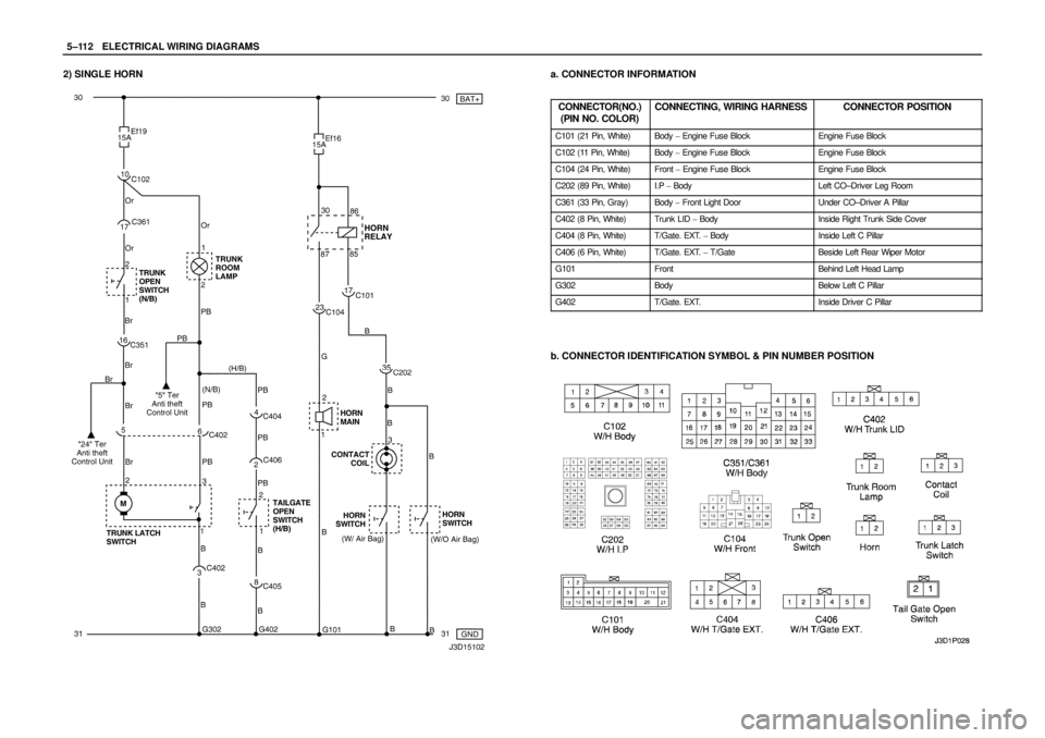
5–112WELECTRICAL WIRING DIAGRAMS
2) SINGLE HORNa. CONNECTOR INFORMATION
CONNECTOR(NO.)
(PIN NO. COLOR)
CONNECTING, WIRING HARNESSCONNECTOR POSITION
C101 (21 Pin, White)Body � Engine Fuse BlockEngine Fuse Block
C102 (11 Pin, White)Body � Engine Fuse BlockEngine Fuse Block
C104 (24 Pin, White)Front � Engine Fuse BlockEngine Fuse Block
C202 (89 Pin, White)I.P � BodyLeft CO–Driver Leg Room
C361 (33 Pin, Gray)Body � Front Light DoorUnder CO–Driver A Pillar
C402 (8 Pin, White)Trunk LID � BodyInside Right Trunk Side Cover
C404 (8 Pin, White)T/Gate. EXT. � BodyInside Left C Pillar
C406 (6 Pin, White)T/Gate. EXT. � T/GateBeside Left Rear Wiper Motor
G101FrontBehind Left Head Lamp
G302BodyBelow Left C Pillar
G402T/Gate. EXT.Inside Driver C Pillar
b. CONNECTOR IDENTIFICATION SYMBOL & PIN NUMBER POSITION
Page 1282 of 2643
5–122WELECTRICAL WIRING DIAGRAMS
17. CLOCK, CIGAR LIGHTER, ASHTRAY ILLUM. LAMP & EXTRA POWER
JACK CIRCUIT
1) M/T
a. CONNECTOR INFORMATION
CONNECTOR(NO.)
(PIN NO. COLOR)
CONNECTING, WIRING HARNESSCONNECTOR POSITION
C101 (21 Pin, White)Body � Engine Fuse BlockEngine Fuse Block
C105 (4 Pin, White)Body � Engine Fuse BlockEngine Fuse Block
C201 (76 Pin, Black)I.P � I.P Fuse BlockI.P Fuse Block
C202 (89 Pin, White)I.P � BodyLeft CO–Driver Leg Room
S203 (Red)I.PBehind Audio Mounting
S204 (Magenta)I.PBehind Audio Mounting
G203I.PBehind Left Audio Bracket
b. CONNECTOR IDENTIFICATION SYMBOL & PIN NUMBER POSITION
J3B1P045
Page 1304 of 2643

(PIN NO. COLOR)
CONNECTING, WIRING HARNESSCONNECTOR POSITION
C")
5–144WELECTRICAL WIRING DIAGRAMS
20. REAR WINDOW DEFROSTER & OSRV MIRROR HEATING SYSTEM
CIRCUITa. CONNECTOR INFORMATION
CONNECTOR(NO.)
(PIN NO. COLOR)
CONNECTING, WIRING HARNESSCONNECTOR POSITION
C101 (21 Pin, White)Body � Engine Fuse BlockEngine Fuse Block
C102 (11 Pin, White)Body � Engine Fuse BlockEngine Fuse Block
C201 (76 Pin, Black)I.P � I.P Fuse BlockI.P Fuse Block
C202 (89 Pin, White)I.P � BodyLeft CO–Driver Leg Room
C208 (15 Pin, White)I.P � FAT CBehind Glove Box
C209 (20 Pin, Black)FAT C � FAT C . A u xBetween Heater Core and Evaporator Core
C351 (33 Pin, Gray)Body � Front Light DoorUnder CO–Driver A Pillar
C361 (33 Pin, Gray)Body � Front Right DoorUnder Driver A Pillar
C404 (8 Pin, White)T/Gate. EXT. � BodyInside Left C Pillar
C405 (8 Pin, White)T/Gate. EXT. � T/GateBeside Left Rear Wiper Motor
C406 (6 Pin, White)T/Gate. EXT. � T/GateBeside Left Rear Wiper Motor
S302 (Brown)BodyLeft CO–Driver Leg Room
G301BodyBelow Driver Cross Member Floor Panel
G303BodyBelow Left CO–Driver Leg Room
G402T/Gate. EXT.Inside Driver C Pillar
b. CONNECTOR IDENTIFICATION SYMBOL & PIN NUMBER POSITION
Page 1306 of 2643
5–146WELECTRICAL WIRING DIAGRAMS
21. ELECTRIC OSRV (OUTSIDE REAR VIEW) MIRROR CIRCUITa. CONNECTOR INFORMATION
CONNECTOR(NO.)
(PIN NO. COLOR)
CONNECTING, WIRING HARNESSCONNECTOR POSITION
C101 (21 Pin, White)Body � Engine Fuse BlockEngine Fuse Block
C201 (76 Pin, Black)I.P � I.P Fuse BlockI.P Fuse Block
C202 (89 Pin, White)I.P � BodyLeft CO–Driver Leg Room
C351 (33 Pin, Gray)Body � Front Light DoorUnder CO–Driver A Pillar
C361 (33 Pin, Gray)Body � Front Right DoorUnder Driver A Pillar
S302 (Brown)BodyLeft CO–Driver Leg Room
G301BodyBelow Driver Cross Member Floor Panel
G303BodyBelow Left CO–Driver Leg Room
b. CONNECTOR IDENTIFICATION SYMBOL & PIN NUMBER POSITION
J3B1P053

 DUAL HORN
a. CONNECTOR INFORMATION
CONNECTOR(NO.)
(PIN NO. COLOR)
CONNECTING, W")
 M/T
a. CONNECTOR INFORMATION
CONNECTOR(NO.)
(PIN NO. COLOR)
CONNECTING, WIRING HARNESSCON")
 MIRROR CIRCUITa. CONNECTOR INFORMATION
CONNECTOR(NO.)
(PIN NO. COLOR)
CONNECTING, WIRING HARNESSCONNECTOR POSITION
C101 (21 Pin")