2004 DAEWOO LACETTI seats
[x] Cancel search: seatsPage 181 of 2643

1.8L DOHC ENGINE MECHANICAL 1C2 – 61
DAEWOO V–121 BL4
4. Inspect the dimension for the valve seat width.
S Intake: 1.2 to 1.4 mm (0.047 to 0.055 inch).
S Exhaust: 1.4 to 1.8 mm (0.055 to 0.070 inch).
5. Inspect the assembly height of the intake valves
and the exhaust valves. If the dimension is exceed-
ed, install new valves. Inspect the assembly height
of the intake valves and the exhaust valves again. If
the valve assembly height is still too large despite
replacing the valves, replace the cylinder head.
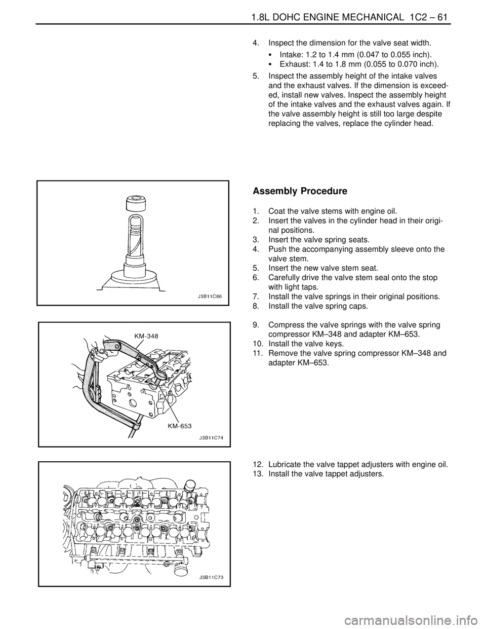
Assembly Procedure
1. Coat the valve stems with engine oil.
2. Insert the valves in the cylinder head in their origi-
nal positions.
3. Insert the valve spring seats.
4. Push the accompanying assembly sleeve onto the
valve stem.
5. Insert the new valve stem seat.
6. Carefully drive the valve stem seal onto the stop
with light taps.
7. Install the valve springs in their original positions.
8. Install the valve spring caps.
9. Compress the valve springs with the valve spring
compressor KM–348 and adapter KM–653.
10. Install the valve keys.
11. Remove the valve spring compressor KM–348 and
adapter KM–653.
12. Lubricate the valve tappet adjusters with engine oil.
13. Install the valve tappet adjusters.
Page 391 of 2643

ENGINE CONTROLS 1F – 145
DAEWOO V–121 BL4
DIAGNOSTIC TROUBLE CODE (DTC) P0135
FRONT HEATED OXYGEN SENSOR HEATER CIRCUIT
NOT FUNCTIONING
Circuit Description
Heated oxygen sensors (HO2S) are used for fuel control
and post catalyst monitoring. Each HO2S compares the
oxygen content of the surrounding air with the oxygen con-
tent in the exhaust stream. The HO2S must reach operat-
ing temperature to provide an accurate voltage signal. A
heating element inside the HO2S minmizes the time re-
quired for the sensor to reach operating temperature. Volt-
age is provided to the heater by the ignition 1 voltage cir-
cuit through a fuse. With the engine running, ground is
provided to the heater by the HO2S heater low control cir-
cuit, through a low side driver within the engine control
module (ECM). The ECM monitors the current flow
through the heater for diagnosis.
If the ECM detects that the HO2S heater current is above
or blelow a specified range, DTC P0135 seats.
Conditions for Setting the DTC
S DTCs P0106, P0117, P0118, P1017 are not set.
S Engine run time is greater than 30 seconds.
S Filtered O2 heater current is less than 0.1 amps.
Action Taken When the DTC SetsS The Malfunction Indicator Lamp (MIL) will illuminate
after three consecutive trip with a fail.
S The ECM will record operating conditions at the
time the diagnostic fails. This information will be
stored in the Freeze Frame and Failure Records
buffers.
S A history Diagnostic Trouble Code (DTC) is stored.
Conditions for Clearing the MIL/DTC
S The MIL will turn off after three consecutive ignition
cycles in which the diagnostic runs without a fault.
S A history DTC will clear after 40 consecutive warm–
up cycles without a fault.
S DTC(s) can be cleared by using the scan tool.
Diagnostic Aids
An intermittent may be caused by rubbed through wire in-
sulation or a wire contacting the exhaust.
Check for poor connection or damaged harness – inspect
harness connectors for the following conditions:
S Improper mating
S Broken locks
S Improperly formed
S Damaged terminals
S Poor terminal–to–wire connection
Page 631 of 2643

ENGINE CONTROLS 1F – 385
DAEWOO V–121 BL4
DIAGNOSTIC TROUBLE CODE (DTC) P0135
FRONT HEATED OXYGEN SENSOR (HO2S1) HEATER
CIRCUIT NOT FUNCTIONING
Circuit Description
Heated oxygen sensors (HO2S) are used for fuel control
and post catalyst monitoring. Each HO2S compares the
oxygen content of the surrounding air with the oxygen con-
tent in the exhaust stream. The HO2S must reach operat-
ing temperature to provide an accurate voltage signal. A
heating element inside the HO2S minmizes the time re-
quired for the sensor to reach operating temperature. Volt-
age is provided to the heater by the ignition 1 voltage cir-
cuit through a fuse. With the engine running, ground is
provided to the heater by the HO2S heater low control cir-
cuit, through a low side driver within the engine control
module (ECM). The ECM monitors the current flow
through the heater for diagnosis.
If the ECM detects that the HO2S heater current is above
or blelow a specified range, DTC P0135 seats.
Conditions for Setting the DTC
S DTCs P0106, P0117, P0118, P1017 are not set.
S Engine run time is greater than 200 seconds.
S Filtered O2 heater current is less than 0.025 amps.
Action Taken When the DTC SetsS The Malfunction Indicator Lamp (MIL) will illuminate
after three consecutive ignition cycle with a fail.
S The ECM will record operating conditions at the
time the diagnostic fails. This information will be
stored in the Freeze Frame and Failure Records
buffers.
S A history Diagnostic Trouble Code (DTC) is stored.
Conditions for Clearing the MIL/DTC
S The MIL will turn off after three consecutive ignition
cycles in which the diagnostic runs without a fault.
S A history DTC will clear after 40 consecutive warm–
up cycles without a fault.
S DTC(s) can be cleared by using the scan tool.
Diagnostic Aids
An intermittent may be caused by rubbed through wire in-
sulation or a wire contacting the exhaust.
Check for poor connection or damaged harness – inspect
harness connectors for the following conditions:
S Improper mating
S Broken locks
S Improperly formed
S Damaged terminals
S Poor terminal–to–wire connection
Page 842 of 2643

1F – 596IENGINE CONTROLS
DAEWOO V–121 BL4
7. Connect the fuel pump harness connector.
8. Connect the fuel vapor line.
9. Connect the fuel tank filler tube.
10. Connect the fuel tank vent tube.
11. Install the fuel tank filler tube clamp at the fuel tank.
12. Install the front muffler. Refer to Section 1G, Ex-
haust System
13. Connect the negative battery cable.
14. Fill the fuel tank.
15. Perform a leak check of the fuel tank and the fuel
line connections.
FUEL PUMP
Removal Procedure
CAUTION : The fuel system is under pressure. To
avoid fuel spillage and the risk of personal injury or
fire, it is necessary to relieve the fuel system pressure
before disconnecting the fuel lines.
1. Relieve the fuel system pressure.
1) Remove the fuel cap.
2) Remove fuel pump fuse Ef18 from the engine
fuse block.
3) Start the engine and allow the engine to stall.
4) Crank the engine for an additional 10 seconds.
2. Disconnect the negative battery cable.
3. Remove the rear seat. Refer to Section 9H, Seats.
4. Remove the fuel pump access cover.
5. Disconnect the electrical connector at the fuel
pump assembly.
6. Disconnect the fuel outlet line.
7. Disconnect the fuel tank return line.
Page 843 of 2643

ENGINE CONTROLS 1F – 597
DAEWOO V–121 BL4
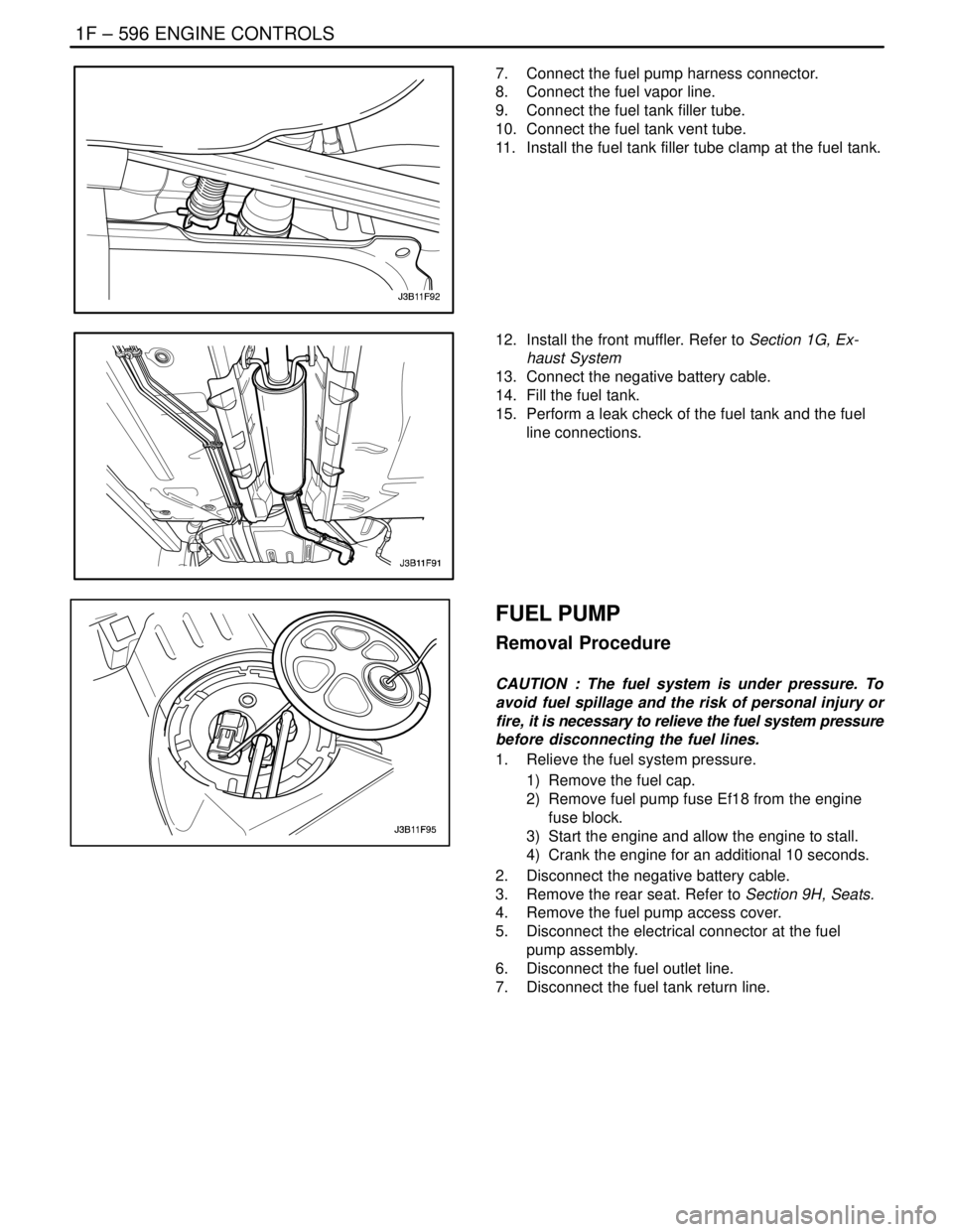
8. Turn the lock ring counterclockwise to clear the
tank tabs.
9. Remove the fuel pump assembly from the tank.
Installation Procedure
1. Clean the gasket mating surface on the fuel tank.
2. Position the new gasket in place.
3. Install the fuel pump into the fuel tank in the same
location as removed for ease of line and connector
installation.
4. Position the lock ring in place and turn it clockwise
until it contacts the tank stop.
5. Connect the fuel pump assembly connector.
6. Install the fuel pump outlet line.
7. Install the fuel tank return line.
8. Install the fuel pump access cover.
9. Connect the negative battery cable.
10. Perform an operational check of the fuel pump.
11. Install the rear seat. Refer to Section 9H, Seats.
FUEL FILTER
Removal Procedure
CAUTION : The fuel system is under pressure. To
avoid fuel spillage and the risk of personal injury or
fire, it is necessary to relieve the fuel system pressure
before disconnecting the fuel lines.
1. Relieve the fuel system pressure. Refer to ” Fuel
System Pressure Relief ” in this section.
2. Disconnect the negative battery cable.
3. Remove the fuel filter mounting bracket assembly
bolt.
4. Remove the fuel filter cover.
5. Disconnect the inlet/outlet fuel lines by moving the
line connector lock forward and pulling the hose off
of the fuel filter tube.
Page 970 of 2643

2E – 8ITIRES AND WHEELS
DAEWOO V–121 BL4
TIRE AND WHEEL
MATCH–MOUNTING
The tires and wheels are match–mounted at the assembly
plant. Match–mounting aligns the radially stiffest part of
the tire, or high spot, to the smallest radius, or low spot, of
the wheel.
The high spot of the tire is originally marked by a red paint
mark or an adhesive label on the outboard sidewall.
The low spot of the wheel will be at the location of the valve
stem.
Before dismounting a tire from its wheel, scribe a line on
the tire at the valve stem to assure that it is remounted in
the same position.
Replacement tires that are of original equipment quality
will have their high and low spot marked in the same man-
ner.
TIRE MOUNTING AND DISMOUNTING
Notice : Use a tire–changing machine to mount or dis-
mount the tires. Follow the equipment manufacturer’s in-
structions. Do not use hand tools or tire irons to change
tires. These tools may damage the beads or the wheel rim.
1. Clean the rim bead seats with a wire brush or
coarse steel wool to remove lubricants, old rubber,
and light rust. Before mounting or dismounting a
tire, lubricate the bead area well with an approved
tire lubricant.
CAUTION : To avoid serious injury, do not stand over
the tire when inflating it, because the bead may break
when it snaps over the safety hump. Do not exceed
275 kPa (40 psi) of air pressure in any tire if the beads
are not seated. If 275 kPa (40 psi) of air pressure will
not seat the beads, deflate the tire. Relubricate the
bead and reinflate the tire. Overinflation may cause
the bead to break and cause serious injury.
2. fter mounting the tire, inflate it until the beads are
seated. Never exceed 275 kPa (40 psi) to seat the
beads.
3. Install the valve core and inflate the tire to the prop-
er pressure. Make sure the locating ring outside of
the bead of the tire shows around the rim flanges of
the wheel on both sides. This positioning of the tire
will insure that the bead of the tire is seated.
Page 1579 of 2643

5A1 – 230IZF 4 HP 16 AUTOMATIC TRANSAXLE
DAEWOO V–121 BL4
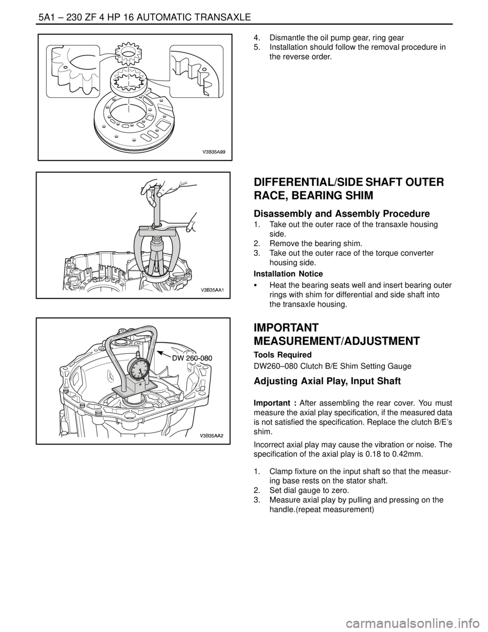
4. Dismantle the oil pump gear, ring gear
5. Installation should follow the removal procedure in
the reverse order.
DIFFERENTIAL/SIDE SHAFT OUTER
RACE, BEARING SHIM
Disassembly and Assembly Procedure
1. Take out the outer race of the transaxle housing
side.
2. Remove the bearing shim.
3. Take out the outer race of the torque converter
housing side.
Installation Notice
S Heat the bearing seats well and insert bearing outer
rings with shim for differential and side shaft into
the transaxle housing.
IMPORTANT
MEASUREMENT/ADJUSTMENT
Tools Required
DW260–080 Clutch B/E Shim Setting Gauge
Adjusting Axial Play, Input Shaft
Important : After assembling the rear cover. You must
measure the axial play specification, if the measured data
is not satisfied the specification. Replace the clutch B/E’s
shim.
Incorrect axial play may cause the vibration or noise. The
specification of the axial play is 0.18 to 0.42mm.
1. Clamp fixture on the input shaft so that the measur-
ing base rests on the stator shaft.
2. Set dial gauge to zero.
3. Measure axial play by pulling and pressing on the
handle.(repeat measurement)
Page 2021 of 2643

MANUAL CONTROL HEATING, VENTILATION AND AIR CONDITIONING SYSTEM 7B – 19
DAEWOO V–121 BL4
MAINTENANCE AND REPAIR
ON–VEHICLE SERVICE
GENERAL A/C SYSTEM SERVICE PROCEDURES
O–RING REPLACEMENT
Important : Even though O–rings may look identical, it is
extremely important that only recommended service re-
placement air conditioning O–rings be used or excessive
leakage of refrigerant may occur.
Important : Always slip the O–ring onto the flange tube to
ensure proper locating and sealing.
Install new Daewoo–approved service replacement air
conditioning (A/C) O–rings whenever a joint or a fitting is
disassembled, except when the O–rings are provided on
new components.
When replacing O–rings on an A/C component or a joint
connection, the fitting design should be identified to en-
sure installation of the correct air conditioning service re-
placement O–ring. Some joint connections and compo-
nents will implement a ”captured” O–ring design fitting that
uses a groove to retain the O–ring. Others do not have a
groove and use a ”non–captured” or ”standard” O–ring.
Assembly and tightening procedures are the same for
both designs, but the O–rings are different.
Notice : Before installation, verify that both O–rings and
fittings have not been nicked or deformed. Deformed or
nicked parts must be replaced. Failure to use the proper
service replacement parts and procedures may result in
excessive refrigerant leakage.
HANDLING REFRIGERANT
CAUTION : Always work in a well–ventilated area and
avoid breathing any refrigerant fumes. If you have dif-
ficulty with breathing, seek medical attention immedi-
ately. If refrigerant comes in contact with any part of
your body, flush the exposed area with water. If a rash
or pain develops, seek medical attention.
Air conditioning systems contain refrigerant. This is a
chemical mixture which requires special handling proce-
dures to avoid personal injury.
Always wear goggles and wrap a clean cloth around the
fittings, the valves and the connections when performing
work that involves opening the refrigerant system. Do not
weld or steam clean on or near any vehicle–installed air
conditioning lines or components.
All refrigerant drums are shipped with a heavy metal screw
cap. The purpose of the cap is to protect the valve and the
safety plug from damage. It is good practice to replace the
cap after each use of the drum.If it is necessary to transport or carry any container of re-
frigerant in a vehicle, do not carry it in the passenger
compartment.
HANDLING OF REFRIGERANT LINES
AND FITTINGS
Notice : Using too low or too high torque when tightening
a fitting can result in loose joints or deformed joint parts.
Both conditions can result in refrigerant leakage.
S Keep all metal tubing lines free of dents or kinks.
Any line restrictions will cause the loss of system
capacity.
S Never bend a flexible hose line to a radius of less
than four times the diameter of the hose.
S Never allow a flexible hose line to come within 65
mm (2–1/2 inches) of the exhaust manifold.
S Inspect flexible hose lines regularly for leaks or
brittleness.
S Replace flexible hose lines with new lines if you find
signs of deterioration or leaking.
S Discharge all refrigerant of the refrigeration system
before disconnecting any fitting in the refrigeration
system.
S Proceed very cautiously regardless of the gauge
readings.
CAUTION : Keep your face and your hands away from
the fitting so that you will not be injured if there hap-
pens to be liquid refrigerant in the line.
S Open the fittings very slowly.
S If you notice pressure when you loosen a fitting,
allow the pressure to bleed off as described under
”Discharging, Adding Oil, Evacuating, and Charging
Procedures for A/C System” in this section.
S Cap or tape any refrigerant line immediately after it
is opened. This will prevent the entrance of mois-
ture and dirt, which can cause internal compressor
wear or plugged lines in the condenser, the evapo-
rator core, the expansion valve, or the compressor
inlet screens.
Important : Use two proper wrenches to connect the O–
ring fittings.
S Back up the opposing fitting to prevent distortion of
the connecting lines or the components.
S Back up both the swagged fitting on the flexible
hose connections and the coupling to which it is
attached with two wrenches to prevent turning the
fitting and damaging the ground seat.
S Keep the O–rings and the seats in perfect condi-
tion. A burr or a piece of dirt may cause a refriger-
ant leak.