Page 2386 of 2643
GLASS AND MIRRORS 9L – 7
DAEWOO V–121 BL4
StepNo Yes Value(s) Action
101. Turn the ignition ON.
2. Check the voltage at terminal 8 (BRN) of the
electric control outside rearview mirror switch
connector.
Is the voltage equal to the specified value?11–14 vGo to Step 12 Go to Step 11
11Repair the open power supply circuit for the electric
control outside rearview mirror switch.
Is the repair complete?–System OK–
12Replace the electric control outside rearview mirror
switch.
Is the repair complete?–System OK–
131. On the side which has the inoperative mirror,
remove the black plastic escutcheon from the
trim panel side of the door.
2. Disconnect the electric control outside rearview
mirror electrical connector.
3. Turn the ignition ON.
4. At the electric control outside rearview mirror
connector, connect a voltmeter between termi-
nal 4 (GRY) and terminal 6 (LT GRN if testing
the driver side or PPL/WHT if testing the pas-
senger side).
5. Operate the in/out adjustment on the switch,
and record the voltage indicated in each switch
position.
6. Connect a voltmeter between terminal 4 (GRY)
and terminal 7 (LT GRN if testing the left side
or RED/WHT if testing the right side).
7. Operate the up/down adjustment on the switch,
and record the voltage indicated in each switch
position.
Does the voltmeter indicate the specified voltage for
each test, with the polarity reversing when the switch
is changed from in to out or up to down?11–14 vGo to Step 14 Go to Step 15
14Replace the electric control outside rearview mirror.
Is the repair complete?–System OK–
Page 2387 of 2643
9L – 8IGLASS AND MIRRORS
DAEWOO V–121 BL4
StepNo Yes Value(s) Action
151. Remove the retaining screw for the electric
control outside rearview mirror and power win-
dow switch assembly.
2. Lift the switch assembly so that the connectors
on the underside are visible.
3. Leave the electric control outside rearview mir-
ror disconnected, but do not disconnect the
mirror switch connector.
4. Turn the ignition ON.
5. At the electric control outside rearview mirror
switch connector, backprobe to measure the
voltage between terminal 4 (GRY) and terminal
6 (LT GRN if testing the left side or GRN/BLK if
testing the right side).
6. Operate the in/out adjustment on the switch,
and record the voltage indicated in each switch
position.
7. Connect a voltmeter between terminal 4 (GRY)
and terminal 7 (WHT if testing the left side or
RED/WHT if testing the right side.
8. Operate the up/down adjustment on the switch,
and record the voltage indicated in each switch
position.
Does the voltmeter indicate the specified voltage for
each test, with the polarity reversing when the switch
was changed from in to out or up to down?11–14 vGo to Step 16 Go to Step 12
16Repair the open circuit between the electric control
outside rearview mirror switch and the electric con-
trol outside rearview mirror connector.
Is the repair complete?–System OK–
FOLDING MIRROR UNIT
StepActionValue(s)YesNo
1Check the folding mirror unit.
Does the folding mirror unit work?–Go to Step 3Go to Step 2
2Check fuse F8.
Is fuse F8 blown?–Go to Step 5 Go to Step 6
31. Check for a short circuit and repair it, if neces-
sary.
2. Replace the fuse.
Is the repair complete?–System OK–
41. On the side of the vehicle which has the mal-
functioning folding mirror unit, remove the black
plastic escutcheon from the trim panel side of
the door.
2. Disconnect the folding mirror unit electrical
connector.
3. Turn the ignition ON.
4. Turn on the folding mirror switch.
5. Use a voltmeter to backprobe terminal 7 (LT
GRN/BLK), 8 (BRN/WHT) at the folding mirror
unit electrical connector.
Does the voltmeter indicate the specified value?11–14 v Go to Step 8 Go to Step 7
Page 2389 of 2643
9L – 10IGLASS AND MIRRORS
DAEWOO V–121 BL4
MAINTENANCE AND REPAIR
ON–VEHICLE SERVICE
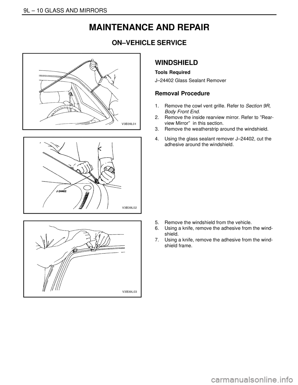
WINDSHIELD
Tools Required
J–24402 Glass Sealant Remover
Removal Procedure
1. Remove the cowl vent grille. Refer to Section 9R,
Body Front End.
2. Remove the inside rearview mirror. Refer to ”Rear-
view Mirror” in this section.
3. Remove the weatherstrip around the windshield.
4. Using the glass sealant remover J–24402, cut the
adhesive around the windshield.
5. Remove the windshield from the vehicle.
6. Using a knife, remove the adhesive from the wind-
shield.
7. Using a knife, remove the adhesive from the wind-
shield frame.
Page 2390 of 2643
GLASS AND MIRRORS 9L – 11
DAEWOO V–121 BL4
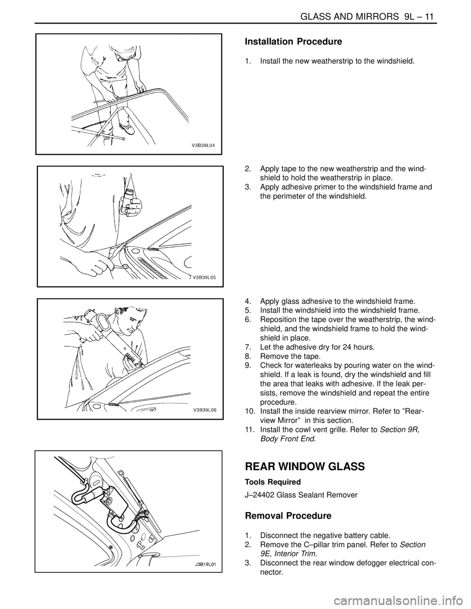
Installation Procedure
1. Install the new weatherstrip to the windshield.
2. Apply tape to the new weatherstrip and the wind-
shield to hold the weatherstrip in place.
3. Apply adhesive primer to the windshield frame and
the perimeter of the windshield.
4. Apply glass adhesive to the windshield frame.
5. Install the windshield into the windshield frame.
6. Reposition the tape over the weatherstrip, the wind-
shield, and the windshield frame to hold the wind-
shield in place.
7. Let the adhesive dry for 24 hours.
8. Remove the tape.
9. Check for waterleaks by pouring water on the wind-
shield. If a leak is found, dry the windshield and fill
the area that leaks with adhesive. If the leak per-
sists, remove the windshield and repeat the entire
procedure.
10. Install the inside rearview mirror. Refer to ”Rear-
view Mirror” in this section.
11. Install the cowl vent grille. Refer to Section 9R,
Body Front End.
REAR WINDOW GLASS
Tools Required
J–24402 Glass Sealant Remover
Removal Procedure
1. Disconnect the negative battery cable.
2. Remove the C–pillar trim panel. Refer to Section
9E, Interior Trim.
3. Disconnect the rear window defogger electrical con-
nector.
Page 2396 of 2643

GLASS AND MIRRORS 9L – 17
DAEWOO V–121 BL4
INSIDE REARVIEW MIRROR
The inside rearview mirror is attached to a support which
is secured to the windshield glass. The support is installed
by the glass supplier using a plastic–polyvinyl butyl adhe-
sive.
Service replacement windshield glass has the mirror sup-
port bonded to the glass assembly. In order to install a de-
tached mirror support or to install a new part, the following
items will be needed:
S Loctite® Minute–Bond Adhesive.
S Original or replacement mirror support.
S Wax marking pencil or crayon.
S Rubbing alcohol.
S Clean paper towel.
S Fine grit sandpaper (grit #320 or #360).
S 2 mm allen wrench.
Installation Procedure
1. Measure the distance from the headliner to the bot-
tom of the location where the mirror support will be
mounted on the windshield.
2. Mark this position on the outside of the glass with a
wax pencil or crayon. Draw a large diameter circle
around the mirror support location on the outside of
the glass.
3. Clean the inside surface of the glass with a domes-
tic scouring cleanser, a glass cleaning solution, or a
polishing compound and paper towels. Rub the
glass until the area is completely dry. When the
area is dry, clean the area with an alcohol–satu-
rated paper towel in order to remove any traces of
the scouring powder or the glass cleaning solution.
4. If the mirror support is new, clean the bonding sur-
face with fine grit sandpaper #320 or #360. If the
original mirror support is being used, all traces of
factory installed adhesive must be removed prior to
reinstallation.
5. Wipe the sanded mirror support with a clean paper
towel saturated with rubbing alcohol. Allow the sup-
port to dry.
6. Follow the adhesive kit manufacturer’s directions
for adhesive application and mirror support prepa-
ration before installing the mirror support to the
glass.
7. Position the mirror support to its premarked posi-
tion. Use steady pressure and press the support
against the glass for 30 to 60 seconds.
8. After 5 minutes, remove the excess adhesive with
an alcohol–moistened towel or a glass–cleaning
solution.
9. Install the inside rearview mirror to the mirror sup-
port with the mounting screw.
Tighten
Tighten the rearview mirror mounting bolt to 1.2 NSm
(11 lb–in).
Page 2397 of 2643
9L – 18IGLASS AND MIRRORS
DAEWOO V–121 BL4
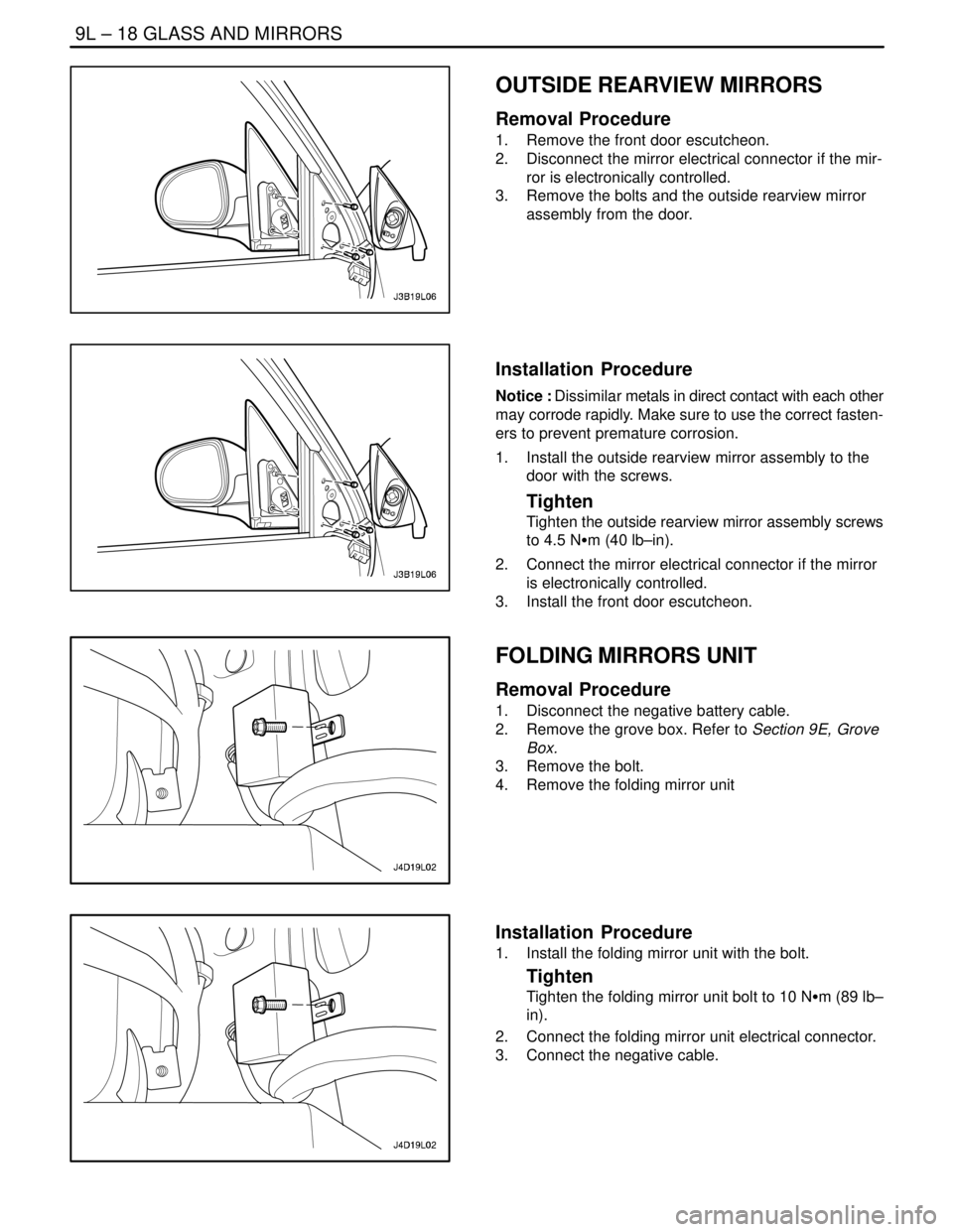
OUTSIDE REARVIEW MIRRORS
Removal Procedure
1. Remove the front door escutcheon.
2. Disconnect the mirror electrical connector if the mir-
ror is electronically controlled.
3. Remove the bolts and the outside rearview mirror
assembly from the door.
Installation Procedure
Notice : Dissimilar metals in direct contact with each other
may corrode rapidly. Make sure to use the correct fasten-
ers to prevent premature corrosion.
1. Install the outside rearview mirror assembly to the
door with the screws.
Tighten
Tighten the outside rearview mirror assembly screws
to 4.5 NSm (40 lb–in).
2. Connect the mirror electrical connector if the mirror
is electronically controlled.
3. Install the front door escutcheon.
FOLDING MIRRORS UNIT
Removal Procedure
1. Disconnect the negative battery cable.
2. Remove the grove box. Refer to Section 9E, Grove
Box.
3. Remove the bolt.
4. Remove the folding mirror unit
Installation Procedure
1. Install the folding mirror unit with the bolt.
Tighten
Tighten the folding mirror unit bolt to 10 NSm (89 lb–
in).
2. Connect the folding mirror unit electrical connector.
3. Connect the negative cable.
Page 2398 of 2643
GLASS AND MIRRORS 9L – 19
DAEWOO V–121 BL4
GENERAL DESCRIPTION
AND SYSTEM OPERATION
STATIONARY GLASS
Stationary glass consists of all the glass on the vehicle
which is immovable within its frame, such as the wind-
shield glass, the back glass, and the inside rearview mir-
ror.
ELECTRIC CONTROL HEATED
OUTSIDE REARVIEW MIRROR
The electric control for the heated outside rearview mirroris on the driver’s side door. The mirror defogger is acti-
vated by the rear window defogger switch.
INSIDE REARVIEW MIRROR
The rearview mirror pivots at the ball–and–socket mirror
pivot and can be manually adjusted up/down and left/right.
FOLDING MIRROR UNIT
The folding mirror system is automatically folding the mir-
ror in parking state.
Page 2436 of 2643
9P – 16IDOORS
DAEWOO V–121 BL4
MAINTENANCE AND REPAIR
ON–VEHICLE SERVICE
OUTSIDE CHANNEL MOLDING
(Front Door Shown, Rear Door Similar)
Removal Procedure
1. Lower the window completely.
2. Remove the outside channel molding screw.
3. Lift the outside channel molding off the door.
Installation Procedure
1. Press the outside channel molding onto the door.
Notice : Dissimilar metals in direct contact with each other
may corrode rapidly. Make sure to use the correct fasten-
ers to prevent premature corrosion.
2. Install the outside channel molding screw.
Tighten
Tighten the outside channel molding screw to 1.3 NSm
(12 lb–in).
3. Raise the window.
FRONT DOOR GLASS RUN
Removal Procedure
1. Remove the outside rearview mirror. Refer to Sec-
tion 9L, Glass and Mirrors.
2. Remove the front door glass. Refer to Section 9L,
Glass and Mirrors.
3. Remove the glass run.