2004 DAEWOO LACETTI length
[x] Cancel search: lengthPage 178 of 2643
1C2 – 58I1.8L DOHC ENGINE MECHANICAL
DAEWOO V–121 BL4
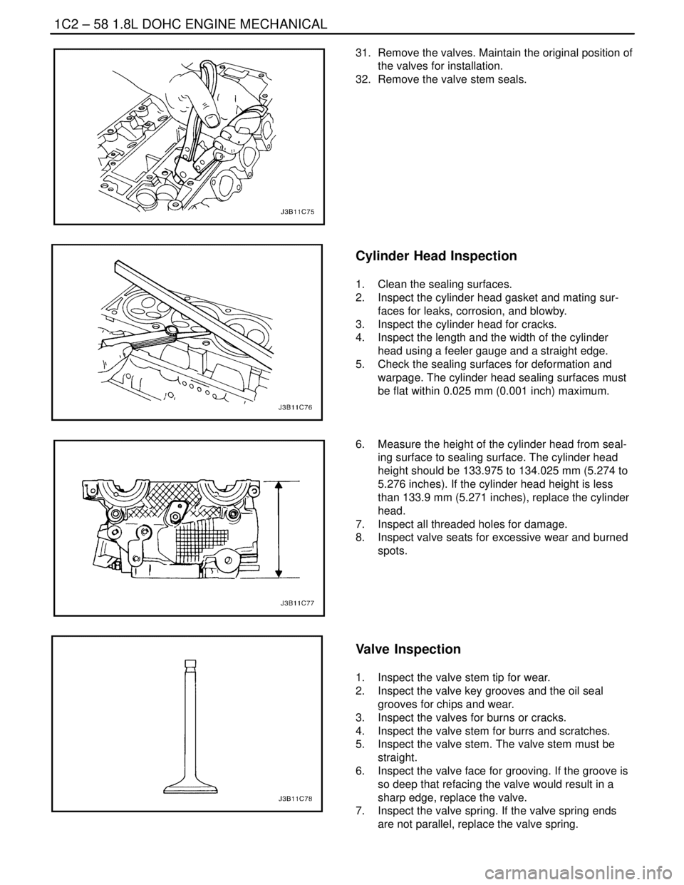
31. Remove the valves. Maintain the original position of
the valves for installation.
32. Remove the valve stem seals.
Cylinder Head Inspection
1. Clean the sealing surfaces.
2. Inspect the cylinder head gasket and mating sur-
faces for leaks, corrosion, and blowby.
3. Inspect the cylinder head for cracks.
4. Inspect the length and the width of the cylinder
head using a feeler gauge and a straight edge.
5. Check the sealing surfaces for deformation and
warpage. The cylinder head sealing surfaces must
be flat within 0.025 mm (0.001 inch) maximum.
6. Measure the height of the cylinder head from seal-
ing surface to sealing surface. The cylinder head
height should be 133.975 to 134.025 mm (5.274 to
5.276 inches). If the cylinder head height is less
than 133.9 mm (5.271 inches), replace the cylinder
head.
7. Inspect all threaded holes for damage.
8. Inspect valve seats for excessive wear and burned
spots.
Valve Inspection
1. Inspect the valve stem tip for wear.
2. Inspect the valve key grooves and the oil seal
grooves for chips and wear.
3. Inspect the valves for burns or cracks.
4. Inspect the valve stem for burrs and scratches.
5. Inspect the valve stem. The valve stem must be
straight.
6. Inspect the valve face for grooving. If the groove is
so deep that refacing the valve would result in a
sharp edge, replace the valve.
7. Inspect the valve spring. If the valve spring ends
are not parallel, replace the valve spring.
Page 187 of 2643
1.8L DOHC ENGINE MECHANICAL 1C2 – 67
DAEWOO V–121 BL4
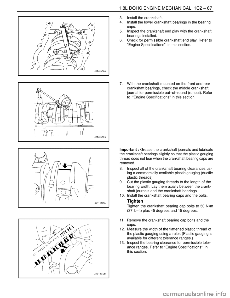
3. Install the crankshaft.
4. Install the lower crankshaft bearings in the bearing
caps.
5. Inspect the crankshaft end play with the crankshaft
bearings installed.
6. Check for permissible crankshaft end play. Refer to
”Engine Specifications” in this section.
7. With the crankshaft mounted on the front and rear
crankshaft bearings, check the middle crankshaft
journal for permissible out–of–round (runout). Refer
to ”Engine Specifications” in this section.
Important : Grease the crankshaft journals and lubricate
the crankshaft bearings slightly so that the plastic gauging
thread does not tear when the crankshaft bearing caps are
removed.
8. Inspect all of the crankshaft bearing clearances us-
ing a commercially available plastic gauging (ductile
plastic threads).
9. Cut the plastic gauging threads to the length of the
bearing width. Lay them axially between the crank-
shaft journals and the crankshaft bearings.
10. Install the crankshaft bearing caps and the bolts.
Tighten
Tighten the crankshaft bearing cap bolts to 50 NSm
(37 lb–ft) plus 45 degrees and 15 degrees.
11. Remove the crankshaft bearing cap bolts and the
caps.
12. Measure the width of the flattened plastic thread of
the plastic gauging using a ruler. (Plastic gauging is
available for different tolerance ranges.)
13. Inspect the bearing clearance for permissible toler-
ance ranges. Refer to ”Engine Specifications” in
this section.
Page 188 of 2643
1C2 – 68I1.8L DOHC ENGINE MECHANICAL
DAEWOO V–121 BL4
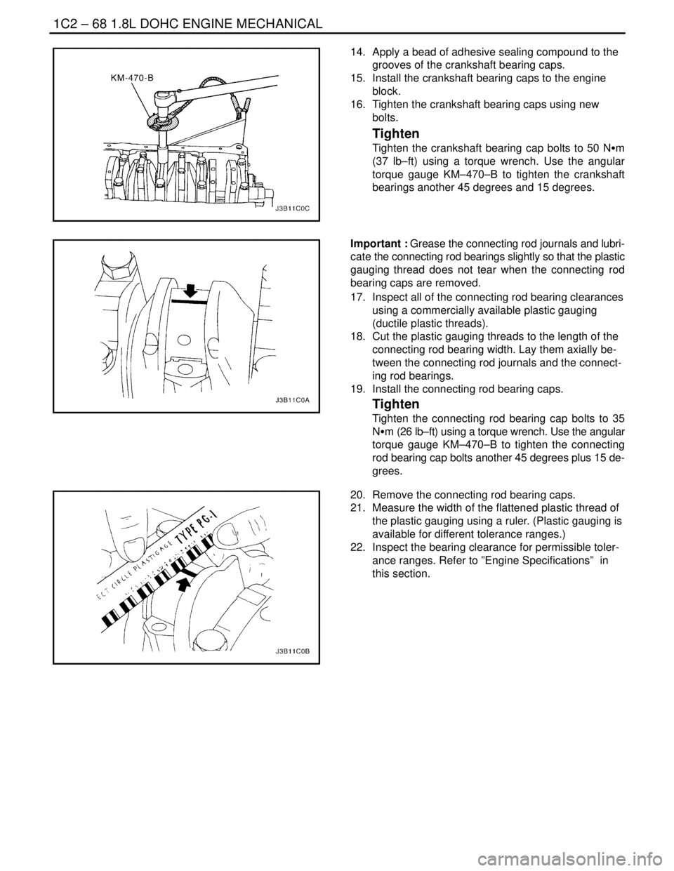
14. Apply a bead of adhesive sealing compound to the
grooves of the crankshaft bearing caps.
15. Install the crankshaft bearing caps to the engine
block.
16. Tighten the crankshaft bearing caps using new
bolts.
Tighten
Tighten the crankshaft bearing cap bolts to 50 NSm
(37 lb–ft) using a torque wrench. Use the angular
torque gauge KM–470–B to tighten the crankshaft
bearings another 45 degrees and 15 degrees.
Important : Grease the connecting rod journals and lubri-
cate the connecting rod bearings slightly so that the plastic
gauging thread does not tear when the connecting rod
bearing caps are removed.
17. Inspect all of the connecting rod bearing clearances
using a commercially available plastic gauging
(ductile plastic threads).
18. Cut the plastic gauging threads to the length of the
connecting rod bearing width. Lay them axially be-
tween the connecting rod journals and the connect-
ing rod bearings.
19. Install the connecting rod bearing caps.
Tighten
Tighten the connecting rod bearing cap bolts to 35
NSm (26 lb–ft) using a torque wrench. Use the angular
torque gauge KM–470–B to tighten the connecting
rod bearing cap bolts another 45 degrees plus 15 de-
grees.
20. Remove the connecting rod bearing caps.
21. Measure the width of the flattened plastic thread of
the plastic gauging using a ruler. (Plastic gauging is
available for different tolerance ranges.)
22. Inspect the bearing clearance for permissible toler-
ance ranges. Refer to ”Engine Specifications” in
this section.
Page 193 of 2643
1.8L DOHC ENGINE MECHANICAL 1C2 – 73
DAEWOO V–121 BL4
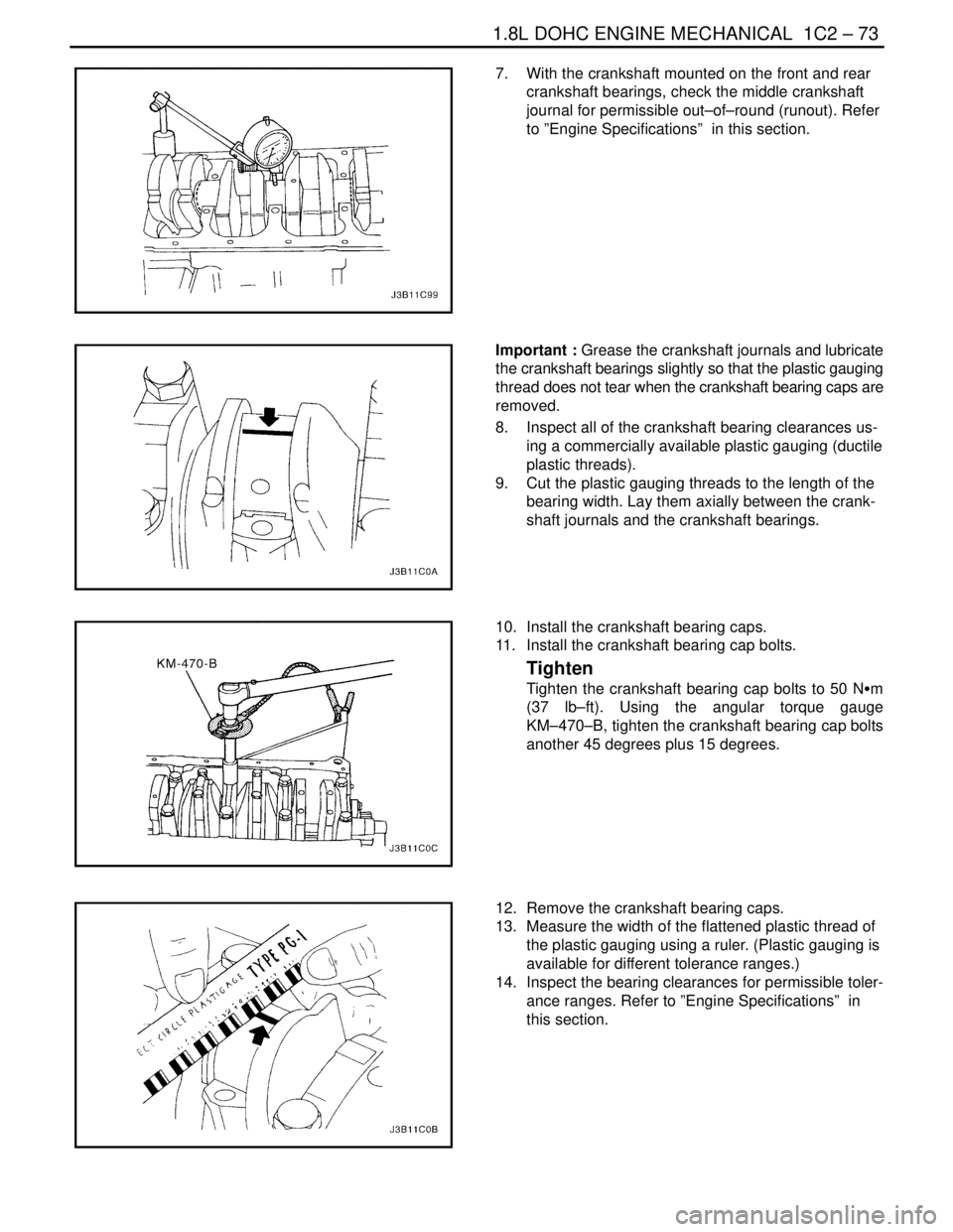
7. With the crankshaft mounted on the front and rear
crankshaft bearings, check the middle crankshaft
journal for permissible out–of–round (runout). Refer
to ”Engine Specifications” in this section.
Important : Grease the crankshaft journals and lubricate
the crankshaft bearings slightly so that the plastic gauging
thread does not tear when the crankshaft bearing caps are
removed.
8. Inspect all of the crankshaft bearing clearances us-
ing a commercially available plastic gauging (ductile
plastic threads).
9. Cut the plastic gauging threads to the length of the
bearing width. Lay them axially between the crank-
shaft journals and the crankshaft bearings.
10. Install the crankshaft bearing caps.
11. Install the crankshaft bearing cap bolts.
Tighten
Tighten the crankshaft bearing cap bolts to 50 NSm
(37 lb–ft). Using the angular torque gauge
KM–470–B, tighten the crankshaft bearing cap bolts
another 45 degrees plus 15 degrees.
12. Remove the crankshaft bearing caps.
13. Measure the width of the flattened plastic thread of
the plastic gauging using a ruler. (Plastic gauging is
available for different tolerance ranges.)
14. Inspect the bearing clearances for permissible toler-
ance ranges. Refer to ”Engine Specifications” in
this section.
Page 194 of 2643
1C2 – 74I1.8L DOHC ENGINE MECHANICAL
DAEWOO V–121 BL4
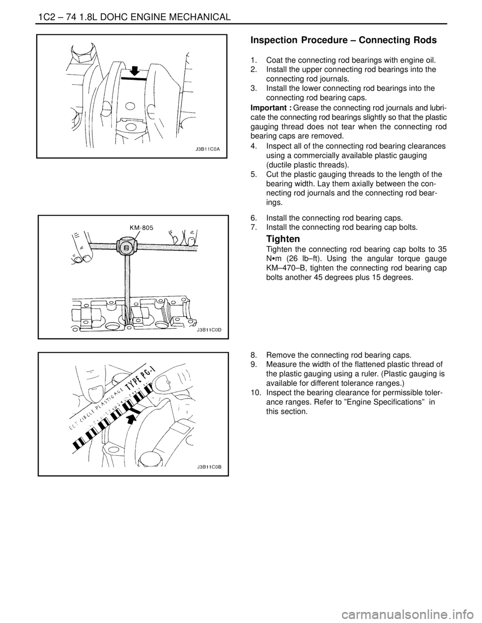
Inspection Procedure – Connecting Rods
1. Coat the connecting rod bearings with engine oil.
2. Install the upper connecting rod bearings into the
connecting rod journals.
3. Install the lower connecting rod bearings into the
connecting rod bearing caps.
Important : Grease the connecting rod journals and lubri-
cate the connecting rod bearings slightly so that the plastic
gauging thread does not tear when the connecting rod
bearing caps are removed.
4. Inspect all of the connecting rod bearing clearances
using a commercially available plastic gauging
(ductile plastic threads).
5. Cut the plastic gauging threads to the length of the
bearing width. Lay them axially between the con-
necting rod journals and the connecting rod bear-
ings.
6. Install the connecting rod bearing caps.
7. Install the connecting rod bearing cap bolts.
Tighten
Tighten the connecting rod bearing cap bolts to 35
NSm (26 lb–ft). Using the angular torque gauge
KM–470–B, tighten the connecting rod bearing cap
bolts another 45 degrees plus 15 degrees.
8. Remove the connecting rod bearing caps.
9. Measure the width of the flattened plastic thread of
the plastic gauging using a ruler. (Plastic gauging is
available for different tolerance ranges.)
10. Inspect the bearing clearance for permissible toler-
ance ranges. Refer to ”Engine Specifications” in
this section.
Page 244 of 2643

1E – 30IENGINE ELECTRICAL
DAEWOO V–121 BL4
GENERAL DESCRIPTION
AND SYSTEM OPERATION
BATTERY
The sealed battery is standard on all cars. There are no
vent plugs in the cover. The battery is completely sealed,
except for two small vent holes in the sides. These vent
holes allow the small amount of gas produced in the bat-
tery to escape. The battery has the following advantages
over conventional batteries:
S No water addition for the life of the battery.
S Overcharge protection. If too much voltage is ap-
plied to the battery, it will not accept as much cur-
rent as a conventional battery. In a conventional
battery, the excess voltage will still try to charge the
battery, leading to gassing, which causes liquid
loss.
S Not as liable to self–discharge as compared to a
conventional battery. This is particularly important
when a battery is left standing for long periods of
time.
S More power available in a lighter and smaller case.
The battery has three major functions in the electrical sys-
tem. First, the battery provides a source of energy for
cranking the engine. Second, the battery acts as a voltage
stabilizer for the electrical system. Finally, the battery can,
for a limited time, provide energy when the electrical de-
mand exceeds the output of the generator.
RATINGS
A battery has two ratings: (1) a reserve capacity rating
designated at 27°C (80°F), which is the time a fully
charged battery will provide 25 amperes current flow at or
above 10.5 volts; (2) a cold cranking amp rating deter-
mined under testing at –18°C (0°F), which indicates the
cranking load capacity.
RESERVE CAPACITY
The reserve capacity is the maximum length of time it is
possible to travel at night with the minimum electrical load
and no generator output. Expressed in minutes, Reserve
Capacity (or RC rating) is the time required for a fully
charged battery, at a temperature of 27°C (80°F) and be-
ing discharged at a current of 25 amperes, to reach a ter-
minal voltage of 10.5 volts.
COLD CRANKING AMPERAGE
The cold cranking amperage test is expressed at a battery
temperature of –18°C (0°F). The current rating is the mini-
mum amperage, which must be maintained by the battery
for 30 seconds at the specified temperature, while meeting
a minimum voltage requirement of 7.2 volts. This rating is
a measure of cold cranking capacity.The battery is not designed to last indefinitely. However,
with proper care, the battery will provide many years of
service.
If the battery tests well, but fails to perform satisfactorily
in service for no apparent reason, the following factors
may point to the cause of the trouble:
S Vehicle accessories are left on overnight.
S Slow average driving speeds are used for short pe-
riods.
S The vehicle’s electrical load is more than the gener-
ator output, particularly with the addition of after-
market equipment.
S Defects in the charging system, such as electrical
shorts, a slipping generator belt, a faulty generator,
or a faulty voltage regulator.
S Battery abuse, including failure to keep the battery
cable terminals clean and tight, or a loose battery
hold–down clamp.
S Mechanical problems in the electrical system, such
as shorted or pinched wires.
BUILT – IN HYDROMETER
The sealed battery has a built–in, temperature–compen-
sated hydrometer in the top of the battery. This hydrome-
ter is to be used with the following diagnostic procedure:
1. When observing the hydrometer, make sure that
the battery has a clean top.
2. Under normal operation, two indications can be ob-
served:
S GREEN DOT VISIBLE – Any green appearance
is interpreted as a ”green dot,” meaning the bat-
tery is ready for testing.
S DARK GREEN DOT IS NOT VISIBLE – If there
is a cranking complaint, the battery should be
tested. The charging and electrical systems
should also be checked at this time.
3. Occasionally, a third condition may appear:
S CLEAR OR BRIGHT YELLOW – This means
the fluid level is below the bottom of the hydrom-
eter. This may have been caused by excessive
or prolonged charging, a broken case, excessive
tipping, or normal battery wear. Finding a battery
in this condition may indicate high charging by a
faulty charging system. Therefore, the charging
and the electrical systems may need to be
checked if a cranking complaint exists. If the
cranking complaint is caused by the battery, re-
place the battery.
CHARGING PROCEDURE
1. Batteries with the green dot showing do not require
charging unless they have just been discharged
(such as in cranking a vehicle).
2. When charging sealed–terminal batteries out of the
vehicle, install the adapter kit. Make sure all the
charger connections are clean and tight. For best
results, batteries should be charged while the elec-
Page 875 of 2643

ENGINE CONTROLS 1F – 629
DAEWOO V–121 BL4
tentially interfere with the operation of the Exhaust Gas
Recirculation (EGR) valve and thereby turn on the MIL.
Small leaks in the exhaust system near the post catalyst
oxygen sensor can also cause the MIL to turn on.
Aftermarket electronics, such as cellular phones, stereos,
and anti–theft devices, may radiate electromagnetic inter-
ference (EMI) into the control system if they are improperly
installed. This may cause a false sensor reading and turn
on the MIL.
Environment
Temporary environmental conditions, such as localized
flooding, will have an effect on the vehicle ignition system.
If the ignition system is rain–soaked, it can temporarily
cause engine misfire and turn on the MIL.
Refueling
A new EOBD diagnostic checks the integrity of the entire
Evaporative (EVAP) Emission system. If the vehicle is re-
started after refueling and the fuel cap is not secured cor-
rectly, the on–board diagnostic system will sense this as
a system fault, turn on the MIL, and set DTC P0440.
Vehicle Marshaling
The transportation of new vehicles from the assembly
plant to the dealership can involve as many as 60 key
cycles within 2 to 3 miles of driving. This type of operation
contributes to the fuel fouling of the spark plugs and will
turn on the MIL with a set DTC P0300.
Poor Vehicle Maintenance
The sensitivity of EOBD diagnostics will cause the MIL to
turn on if the vehicle is not maintained properly. Restricted
air filters, fuel filters, and crankcase deposits due to lack
of oil changes or improper oil viscosity can trigger actual
vehicle faults that were not previously monitored prior to
EOBD. Poor vehicle maintenance can not be classified as
a ”non–vehicle fault,” but with the sensitivity of EOBD
diagnostics, vehicle maintenance schedules must be
more closely followed.
Severe Vibration
The Misfire diagnostic measures small changes in the
rotational speed of the crankshaft. Severe driveline vibra-
tions in the vehicle, such as caused by an excessive
amount of mud on the wheels, can have the same effect
on crankshaft speed as misfire and, therefore, may set
DTC P0300.
Related System Faults
Many of the EOBD system diagnostics will not run if the
engine controlmodule (ECM) detects a fault on a related
system or component. One example would be that if the
ECM detected a Misfire fault, the diagnostics on the cata-
lytic converter would be suspended until the Misfire fault
was repaired. If the Misfire fault is severe enough, the cat-
alytic converter can be damaged due to overheating andwill never set a Catalyst DTC until the Misfire fault is re-
paired and the Catalyst diagnostic is allowed to run to
completion. If this happens, the customer may have to
make two trips to the dealership in order to repair the ve-
hicle.
SERIAL DATA COMMUNICATIONS
Class II Serial Data Communications
Government regulations require that all vehicle manufac-
turers establish a common communication system. This
vehicle utilizes the ”Class II” communication system. Each
bit of information can have one of two lengths: long or
short. This allows vehicle wiring to be reduced by transmit-
ting and receiving multiple signals over a single wire. The
messages carried on Class II data streams are also priori-
tized. If two messages attempt to establish communica-
tions on the data line at the same time, only the message
with higher priority will continue. The device with the lower
priority message must wait. Themost significant result of
this regulation is that it provides scan tool manufacturers
with the capability to access data from any make or model
vehicle that is sold.
The data displayed on the other scan tool will appear the
same, with some exceptions. Some scan tools will only be
able to display certain vehicle parameters as values that
are a coded representation of the true or actual value. On
this vehicle the scan tool displays the actual values for ve-
hicle parameters. It will not be necessary to perform any
conversions from coded values to actual values.
ON–BOARD DIAGNOSTIC (EOBD)
On–Board Diagnostic Tests
A diagnostic test is a series of steps, the result of which is
a pass or fail reported to the diagnostic executive. When
a diagnostic test reports a pass result, the diagnostic
executive records the following data:
S The diagnostic test has been completed since the
last ignition cycle.
S The diagnostic test has passed during the current
ignition cycle.
S The fault identified by the diagnostic test is not cur-
rently active.
When a diagnostic test reports a fail result, the diagnostic
executive records the following data:
S The diagnostic test has been completed since the
last ignition cycle.
S The fault identified by the diagnostic test is current-
ly active.
S The fault has been active during this ignition cycle.
S The operating conditions at the time of the failure.
Remember, a fuel trim Diagnostic Trouble Code (DTC)
may be triggered by a list of vehicle faults. Make use of all
information available (other DTCs stored, rich or lean con-
dition, etc.) when diagnosing a fuel trim fault.
Page 906 of 2643

SUSPENSION DIAGNOSIS 2A – 5
DAEWOO V–121 BL4
Steering Wheel Kickback
ChecksAction
Inspect for air in the power steering system.Purge the power steering system of air.
Inspect for a loose steering gear mounting.Tighten the steering gear mounting bracket nuts.
Inspect the joint from the column to the steering gear for
loose connections or wear.Tighten the intermediate shaft pinch bolts. Replace the in-
termediate shaft as needed.
Inspect for loose tie rod ends.Tighten the tie rod ends. Replace the outer tie rods as
needed.
Inspect for loose or worn wheel bearings.Tighten the drive axle nut. Replace the wheel bearings as
needed.
Steering Wheel Surges or Jerks
ChecksAction
Check the hydraulic system. Test the power steering sys-
tem pressure with a gauge.Replace the seals and the hoses as needed.
Inspect for a sluggish steering gear valve.Clean the pinion valve assembly. Replace the pinion valve
assembly as needed.
Inspect for a loose power steering pump serpentine belt.Adjust the power steering pump serpentine belt.
Cupped Tires
ChecksAction
Check the front–wheel and the rear–wheel alignment.Align the front and the rear wheels.
Inspect for worn strut dampeners.Replace the strut dampeners.
Inspect for worn or loose wheel bearings.Tighten the drive axle nut. Replace the wheel bearings as
needed.
Inspect for excessive tire or wheel runout.Match–mount the tires. Replace the tires as needed. Re-
place the wheels as needed.
Inspect for a worn ball joint.Replace the ball joint.
Check the steering gear preload adjustment.Perform a rack bearing preload adjustment.
TORQUE STEER
A degree of torque steer to the right may be experienced
during the use of heavy throttle on some front–wheel drive
cars with drive axles of unequal length. This torque steer
to the right results from the right drive axle being longer
than the left drive axle, which creates a difference in the
drive axle angle. Cars with intermediate shaft assemblies
have axles of almost equal length.
A difference in the drive axle lengths results in more torque
toe–in in the left front wheel. You will notice the torque toe–
in when the vehicle accelerates from a standing start or at
lower speeds.
Inspection Procedure
1. Place a small piece of tape at the top center of the
steering wheel.2. Note the inches of steering wheel deflection re-
quired to keep the vehicle straight during heavy ac-
celeration.
3. Compare this finding with similar cars.
Factors that may cause torque steer to be more apparent
on a particular vehicle include:
S Variations in the tire and wheel assemblies. This
has the most significant effect on torque steer. A
slightly smaller diameter on the right front tire will
increase a right torque lead.
S Large differences in the right and the left front tire
pressure.
S Looseness in the control arm bushings, the tie rod
assemblies, or the steering gear mounting. This
looseness permits a front wheel to pull forward and
toe–in under a torque greater than the wheel on the
opposite side. A loose suspension component may
result in an opposite lead upon deceleration.