2004 DAEWOO LACETTI hood cable
[x] Cancel search: hood cablePage 1160 of 2643
4G – 8IPARKING BRAKE
DAEWOO V–121 BL4
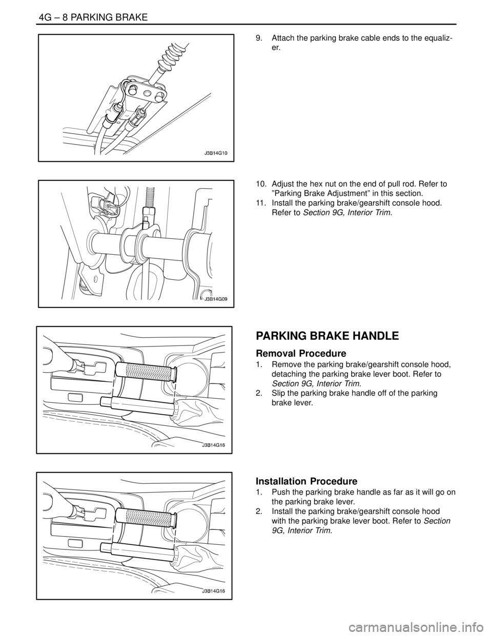
9. Attach the parking brake cable ends to the equaliz-
er.
10. Adjust the hex nut on the end of pull rod. Refer to
”Parking Brake Adjustment” in this section.
11. Install the parking brake/gearshift console hood.
Refer to Section 9G, Interior Trim.
PARKING BRAKE HANDLE
Removal Procedure
1. Remove the parking brake/gearshift console hood,
detaching the parking brake lever boot. Refer to
Section 9G, Interior Trim.
2. Slip the parking brake handle off of the parking
brake lever.
Installation Procedure
1. Push the parking brake handle as far as it will go on
the parking brake lever.
2. Install the parking brake/gearshift console hood
with the parking brake lever boot. Refer to Section
9G, Interior Trim.
Page 2291 of 2643
9D – 14IWIPERS/WASHER SYSTEMS
DAEWOO V–121 BL4
MAINTENANCE AND REPAIR
ON–VEHICLE SERVICE
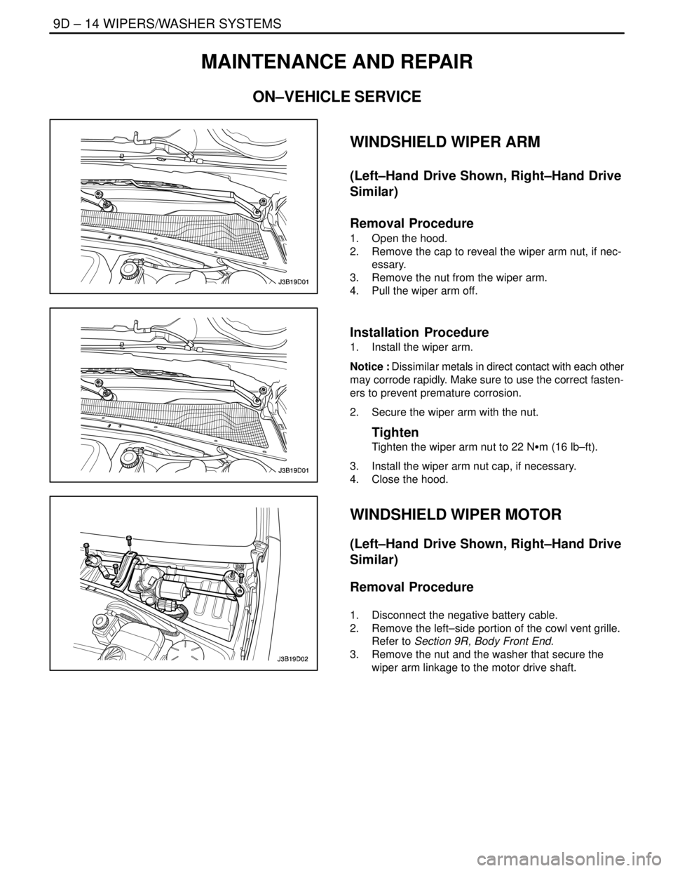
WINDSHIELD WIPER ARM
(Left–Hand Drive Shown, Right–Hand Drive
Similar)
Removal Procedure
1. Open the hood.
2. Remove the cap to reveal the wiper arm nut, if nec-
essary.
3. Remove the nut from the wiper arm.
4. Pull the wiper arm off.
Installation Procedure
1. Install the wiper arm.
Notice : Dissimilar metals in direct contact with each other
may corrode rapidly. Make sure to use the correct fasten-
ers to prevent premature corrosion.
2. Secure the wiper arm with the nut.
Tighten
Tighten the wiper arm nut to 22 NSm (16 lb–ft).
3. Install the wiper arm nut cap, if necessary.
4. Close the hood.
WINDSHIELD WIPER MOTOR
(Left–Hand Drive Shown, Right–Hand Drive
Similar)
Removal Procedure
1. Disconnect the negative battery cable.
2. Remove the left–side portion of the cowl vent grille.
Refer to Section 9R, Body Front End.
3. Remove the nut and the washer that secure the
wiper arm linkage to the motor drive shaft.
Page 2295 of 2643
9D – 18IWIPERS/WASHER SYSTEMS
DAEWOO V–121 BL4
Installation Procedure
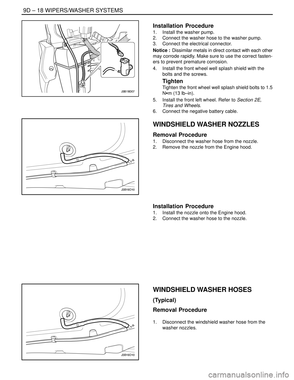
1. Install the washer pump.
2. Connect the washer hose to the washer pump.
3. Connect the electrical connector.
Notice : Dissimilar metals in direct contact with each other
may corrode rapidly. Make sure to use the correct fasten-
ers to prevent premature corrosion.
4. Install the front wheel well splash shield with the
bolts and the screws.
Tighten
Tighten the front wheel well splash shield bolts to 1.5
NSm (13 lb–in).
5. Install the front left wheel. Refer to Section 2E,
Tires and Wheels.
6. Connect the negative battery cable.
WINDSHIELD WASHER NOZZLES
Removal Procedure
1. Disconnect the washer hose from the nozzle.
2. Remove the nozzle from the Engine hood.
Installation Procedure
1. Install the nozzle onto the Engine hood.
2. Connect the washer hose to the nozzle.
WINDSHIELD WASHER HOSES
(Typical)
Removal Procedure
1. Disconnect the windshield washer hose from the
washer nozzles.
Page 2341 of 2643

SECTION : 9G
INTERIOR TRIM
CAUTION : Disconnect the negative battery cable before removing or installing any electrical unit or when a tool
or equipment could easily come in contact with exposed electrical terminals. Disconnecting this cable will help
prevent personal injury and damage to the vehicle. The ignition must also be in LOCK unless otherwise noted.
TABLE OF CONTENTS
SPECIFICATIONS9G–1 . . . . . . . . . . . . . . . . . . . . . . . . . .
Fastener Tightening Specifications 9G–1. . . . . . . . . . .
SPECIAL TOOLS9G–2 . . . . . . . . . . . . . . . . . . . . . . . . . . .
Special Tools Table 9G–2. . . . . . . . . . . . . . . . . . . . . . . .
MAINTENANCE AND REPAIR9G–3 . . . . . . . . . . . . . . .
ON–VEHICLE SERVICE 9G–3. . . . . . . . . . . . . . . . . . . . .
Front Door Trim Panel 9G–3. . . . . . . . . . . . . . . . . . . . . .
Rear Door Trim Panel 9G–4. . . . . . . . . . . . . . . . . . . . . .
A–pillar Trim Panel 9G–4. . . . . . . . . . . . . . . . . . . . . . . . .
Upper B–pillar Trim Panel 9G–5. . . . . . . . . . . . . . . . . . .
Lower B–pillar Trim Panel 9G–5. . . . . . . . . . . . . . . . . . .
C–pillar Trim Panel 9G–6. . . . . . . . . . . . . . . . . . . . . . . . .
Deck Lid Sill Plate Cover 9G–6. . . . . . . . . . . . . . . . . . .
Front Rocker Trim Panel 9G–7. . . . . . . . . . . . . . . . . . . .
Rear Rocker Trim Panel 9G–7. . . . . . . . . . . . . . . . . . . .
Front Wheelhouse Trim 9G–8. . . . . . . . . . . . . . . . . . . . .
Rear Wheelhouse Trim 9G–8. . . . . . . . . . . . . . . . . . . . .
Floor Console 9G–9. . . . . . . . . . . . . . . . . . . . . . . . . . . . . Floor Carpet 9G–10. . . . . . . . . . . . . . . . . . . . . . . . . . . . .
Luggage Compartment Rear Low Cover 9G–11. . . . .
Luggage Compartment Wheelhouse Trim
Panel 9G–12. . . . . . . . . . . . . . . . . . . . . . . . . . . . . . . . . .
Driver’s Side Knee Bolster 9G–12. . . . . . . . . . . . . . . . .
Hatchback Door Lower Garnish Molding 9G–13. . . . .
Hatchback Door Upper Garnish Molding 9G–14. . . . .
Luggage Compartment Wheelhouse Trim Panel
(HATCHBACK) 9G–14. . . . . . . . . . . . . . . . . . . . . . . . .
Luggage Compartment Rear Trim Panel 9G–14. . . . .
GENERAL DESCRIPTION AND SYSTEM
OPERATION9G–16 . . . . . . . . . . . . . . . . . . . . . . . . . . . . .
Interior Trim Panels 9G–16. . . . . . . . . . . . . . . . . . . . . . .
Pressure Relief Vent 9G–16. . . . . . . . . . . . . . . . . . . . . .
Floor Console 9G–16. . . . . . . . . . . . . . . . . . . . . . . . . . . .
Floor Carpet 9G–16. . . . . . . . . . . . . . . . . . . . . . . . . . . . .
Rear Compartment Security Cover
(HATCHBACK) 9G–16. . . . . . . . . . . . . . . . . . . . . . . . .
SPECIFICATIONS
FASTENER TIGHTENING SPECIFICATIONS
ApplicationNSmLb–FtLb–In
Door Trim Panel Screws2.5–22
Driver’s Side Knee Bolster Mounting Bolts10–89
Floor Console Screws2.5–22
Gearshift Housing Bolts8–70
Hood Latch Release Handle Mounting Screw3–27
Seat Belt Anchor Bolt3828–
Page 2352 of 2643
9G – 12IINTERIOR TRIM
DAEWOO V–121 BL4
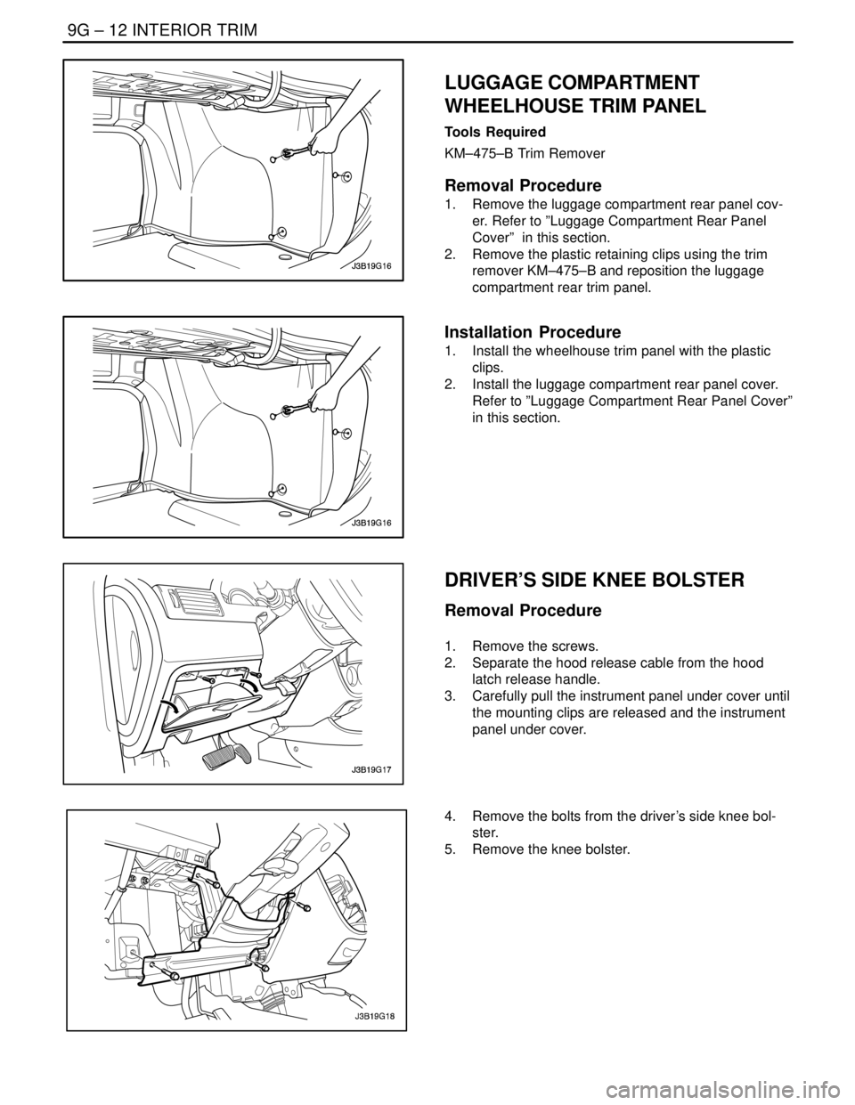
LUGGAGE COMPARTMENT
WHEELHOUSE TRIM PANEL
Tools Required
KM–475–B Trim Remover
Removal Procedure
1. Remove the luggage compartment rear panel cov-
er. Refer to ”Luggage Compartment Rear Panel
Cover” in this section.
2. Remove the plastic retaining clips using the trim
remover KM–475–B and reposition the luggage
compartment rear trim panel.
Installation Procedure
1. Install the wheelhouse trim panel with the plastic
clips.
2. Install the luggage compartment rear panel cover.
Refer to ”Luggage Compartment Rear Panel Cover”
in this section.
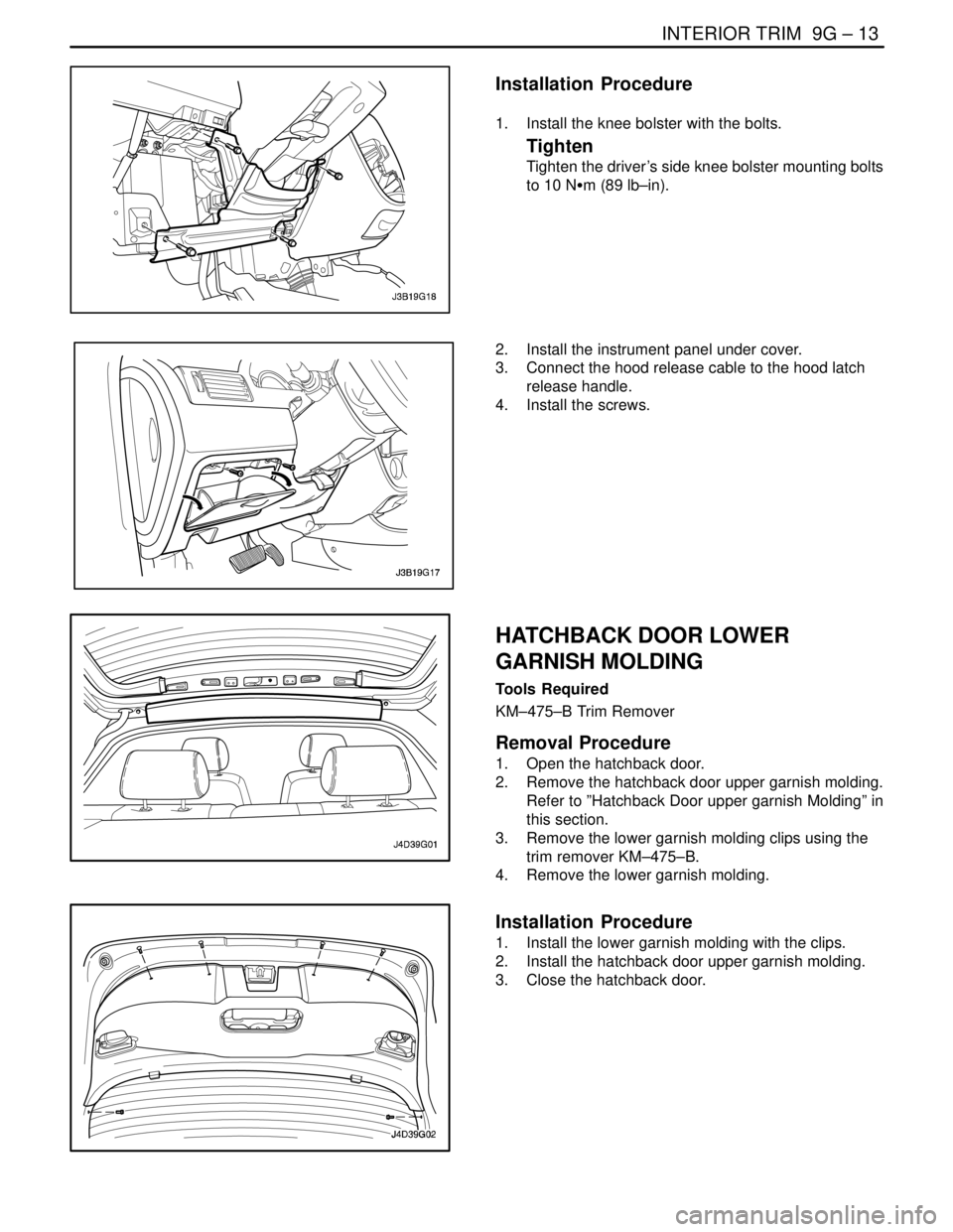
DRIVER’S SIDE KNEE BOLSTER
Removal Procedure
1. Remove the screws.
2. Separate the hood release cable from the hood
latch release handle.
3. Carefully pull the instrument panel under cover until
the mounting clips are released and the instrument
panel under cover.
4. Remove the bolts from the driver’s side knee bol-
ster.
5. Remove the knee bolster.
Page 2353 of 2643
INTERIOR TRIM 9G – 13
DAEWOO V–121 BL4
Installation Procedure
1. Install the knee bolster with the bolts.
Tighten
Tighten the driver’s side knee bolster mounting bolts
to 10 NSm (89 lb–in).
2. Install the instrument panel under cover.
3. Connect the hood release cable to the hood latch
release handle.
4. Install the screws.
HATCHBACK DOOR LOWER
GARNISH MOLDING
Tools Required
KM–475–B Trim Remover
Removal Procedure
1. Open the hatchback door.
2. Remove the hatchback door upper garnish molding.
Refer to ”Hatchback Door upper garnish Molding” in
this section.
3. Remove the lower garnish molding clips using the
trim remover KM–475–B.
4. Remove the lower garnish molding.
Installation Procedure
1. Install the lower garnish molding with the clips.
2. Install the hatchback door upper garnish molding.
3. Close the hatchback door.
Page 2462 of 2643

SECTION : 9R
BODY FRONT END
TABLE OF CONTENTS
SPECIFICATIONS9R–1 . . . . . . . . . . . . . . . . . . . . . . . . . .
Fastener Tightening Specifications 9R–1. . . . . . . . . . .
MAINTENANCE AND REPAIR9R–2 . . . . . . . . . . . . . . .
ON–VEHICLE SERVICE 9R–2. . . . . . . . . . . . . . . . . . . . .
Lubrication 9R–2. . . . . . . . . . . . . . . . . . . . . . . . . . . . . . . .
Fasteners 9R–2. . . . . . . . . . . . . . . . . . . . . . . . . . . . . . . .
Anticorrosion Materials 9R–2. . . . . . . . . . . . . . . . . . . . .
Front End Sealing 9R–2. . . . . . . . . . . . . . . . . . . . . . . . .
Cowl Vent Grille 9R–2. . . . . . . . . . . . . . . . . . . . . . . . . . .
Hood 9R–3. . . . . . . . . . . . . . . . . . . . . . . . . . . . . . . . . . . . . Hood Hinges 9R–3. . . . . . . . . . . . . . . . . . . . . . . . . . . . . .
Hood Prop Rod 9R–4. . . . . . . . . . . . . . . . . . . . . . . . . . . .
Hood Secondary Latch 9R–4. . . . . . . . . . . . . . . . . . . . .
Hood Latch Release Cable 9R–5. . . . . . . . . . . . . . . . . .
Notchback Radiator Grille 9R–5. . . . . . . . . . . . . . . . . . .
Hatchback Radiator Grille 9R–6. . . . . . . . . . . . . . . . . . .
Front Wheel Well Splash Shield 9R–6. . . . . . . . . . . . .
Fender 9R–7. . . . . . . . . . . . . . . . . . . . . . . . . . . . . . . . . . .
GENERAL DESCRIPTION AND SYSTEM
OPERATION9R–10 . . . . . . . . . . . . . . . . . . . . . . . . . . . . .
Body Front End 9R–10. . . . . . . . . . . . . . . . . . . . . . . . . .
SPECIFICATIONS
FASTENER TIGHTENING SPECIFICATIONS
ApplicationNSmLb–FtLb–In
A–Pillar Fender Bolt10–89
Fender Bolt (Front of Fascia)4–35
Front Bumper Fascia–to–Fender Bolt2.5–22
Hinge Bolts2720–
Hood–to–Hinge Bolts2720–
Hood Latch Bolts8–71
Hood Release Handle Nuts4–35
Lower Fender Bolt10–89
Radiator Grille Nuts4–35
Splash Shield screws2–18
Upper Fender Bolts10–89
Page 2466 of 2643
BODY FRONT END 9R – 5
DAEWOO V–121 BL4
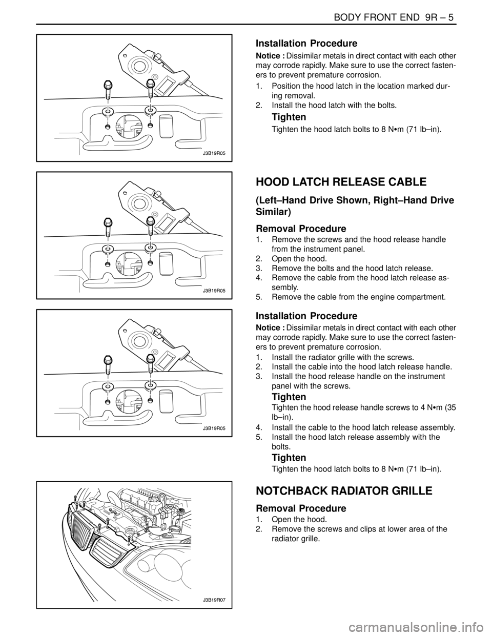
Installation Procedure
Notice : Dissimilar metals in direct contact with each other
may corrode rapidly. Make sure to use the correct fasten-
ers to prevent premature corrosion.
1. Position the hood latch in the location marked dur-
ing removal.
2. Install the hood latch with the bolts.
Tighten
Tighten the hood latch bolts to 8 NSm (71 lb–in).
HOOD LATCH RELEASE CABLE
(Left–Hand Drive Shown, Right–Hand Drive
Similar)
Removal Procedure
1. Remove the screws and the hood release handle
from the instrument panel.
2. Open the hood.
3. Remove the bolts and the hood latch release.
4. Remove the cable from the hood latch release as-
sembly.
5. Remove the cable from the engine compartment.
Installation Procedure
Notice : Dissimilar metals in direct contact with each other
may corrode rapidly. Make sure to use the correct fasten-
ers to prevent premature corrosion.
1. Install the radiator grille with the screws.
2. Install the cable into the hood latch release handle.
3. Install the hood release handle on the instrument
panel with the screws.
Tighten
Tighten the hood release handle screws to 4 NSm (35
lb–in).
4. Install the cable to the hood latch release assembly.
5. Install the hood latch release assembly with the
bolts.
Tighten
Tighten the hood latch bolts to 8 NSm (71 lb–in).
NOTCHBACK RADIATOR GRILLE
Removal Procedure
1. Open the hood.
2. Remove the screws and clips at lower area of the
radiator grille.