2004 DAEWOO LACETTI air bleeding
[x] Cancel search: air bleedingPage 1142 of 2643

ANTILOCK BRAKE SYSTEM 4F – 61
DAEWOO V–121 BL4
BLEEDING SYSTEM
Replacement modulators are shipped already filled and
bled. In normal procedures requiring removal of the modu-
lator, such as to replace the EBCM, air will not enter the
modulator, and normal bleeding will be all that is needed.
For this procedure, refer to Section 4A, Hydraulic Brakes.
If air enters the hydraulic modulator, or if an unfilled modu-
lator is installed, use the brake bleeding program in the
scan tool to bleed the modulator. Manual bleeding of the
hydraulic modulator is not possible.
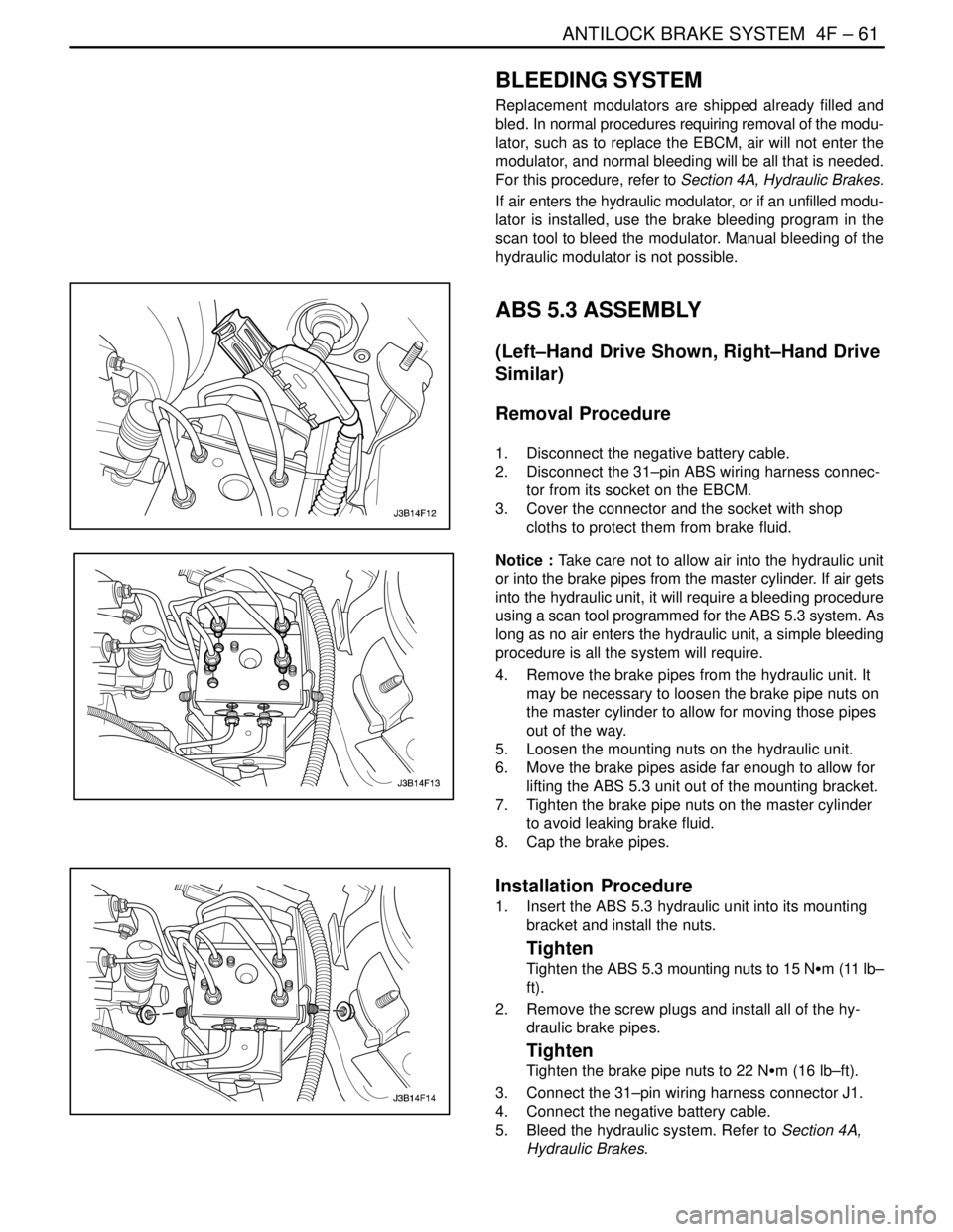
ABS 5.3 ASSEMBLY
(Left–Hand Drive Shown, Right–Hand Drive
Similar)
Removal Procedure
1. Disconnect the negative battery cable.
2. Disconnect the 31–pin ABS wiring harness connec-
tor from its socket on the EBCM.
3. Cover the connector and the socket with shop
cloths to protect them from brake fluid.
Notice : Take care not to allow air into the hydraulic unit
or into the brake pipes from the master cylinder. If air gets
into the hydraulic unit, it will require a bleeding procedure
using a scan tool programmed for the ABS 5.3 system. As
long as no air enters the hydraulic unit, a simple bleeding
procedure is all the system will require.
4. Remove the brake pipes from the hydraulic unit. It
may be necessary to loosen the brake pipe nuts on
the master cylinder to allow for moving those pipes
out of the way.
5. Loosen the mounting nuts on the hydraulic unit.
6. Move the brake pipes aside far enough to allow for
lifting the ABS 5.3 unit out of the mounting bracket.
7. Tighten the brake pipe nuts on the master cylinder
to avoid leaking brake fluid.
8. Cap the brake pipes.
Installation Procedure
1. Insert the ABS 5.3 hydraulic unit into its mounting
bracket and install the nuts.
Tighten
Tighten the ABS 5.3 mounting nuts to 15 NSm (11 lb–
ft).
2. Remove the screw plugs and install all of the hy-
draulic brake pipes.
Tighten
Tighten the brake pipe nuts to 22 NSm (16 lb–ft).
3. Connect the 31–pin wiring harness connector J1.
4. Connect the negative battery cable.
5. Bleed the hydraulic system. Refer to Section 4A,
Hydraulic Brakes.
Page 1888 of 2643

SECTION : 5C
CLUTCH
CAUTION : Disconnect the negative battery cable before removing or installing any electrical unit or when a tool
or equipment could easily come in contact with exposed electrical terminals. Disconnecting this cable will help
prevent personal injury and damage to the vehicle. The ignition must also be in LOCK unless otherwise noted.
TABLE OF CONTENTS
SPECIFICATIONS5C–1 . . . . . . . . . . . . . . . . . . . . . . . . . .
Fastener Tightening Specifications 5C–1. . . . . . . . . . .
SPECIAL TOOLS5C–2 . . . . . . . . . . . . . . . . . . . . . . . . . . .
Special Tools Table 5C–2. . . . . . . . . . . . . . . . . . . . . . . .
DIAGNOSIS5C–2 . . . . . . . . . . . . . . . . . . . . . . . . . . . . . . . .
Clutch Operation 5C–2. . . . . . . . . . . . . . . . . . . . . . . . . .
COMPONENT LOCATOR5C–4 . . . . . . . . . . . . . . . . . . . .
Clutch Components 5C–4. . . . . . . . . . . . . . . . . . . . . . . .
MAINTENANCE AND REPAIR5C–6 . . . . . . . . . . . . . . .
ON–VEHICLE SERVICE 5C–6. . . . . . . . . . . . . . . . . . . . .
Clutch Pedal 5C–6. . . . . . . . . . . . . . . . . . . . . . . . . . . . . . Clutch Pedal Adjustment 5C–7. . . . . . . . . . . . . . . . . . . .
Clutch Release Point Adjustment 5C–8. . . . . . . . . . . .
Air Bleeding 5C–8. . . . . . . . . . . . . . . . . . . . . . . . . . . . . . .
Pressure Plate and Clutch Disc 5C–8. . . . . . . . . . . . . .
Clutch Master Cylinder Assembly 5C–10. . . . . . . . . . .
Concentric Slave Cylinder 5C–12. . . . . . . . . . . . . . . . . .
GENERAL DESCRIPTION AND SYSTEM
OPERATION5C–14 . . . . . . . . . . . . . . . . . . . . . . . . . . . . .
Driving Members 5C–14. . . . . . . . . . . . . . . . . . . . . . . . .
Driven Members 5C–14. . . . . . . . . . . . . . . . . . . . . . . . . .
Operating Members 5C–14. . . . . . . . . . . . . . . . . . . . . . .
SPECIFICATIONS
FASTENER TIGHTENING SPECIFICATIONS
ApplicationNSmLb–FtLb–In
Clutch Master Cylinder nuts2216–
Concentric Slave Cylinder Retaining Bolts7–62
Concentric Slave Cylinder–to–Clutch Oil Pipe Screw1511–
Pressure Plate–to–Flywheel Bolts1511–
Page 1889 of 2643

5C – 2ICLUTCH
DAEWOO V–121 BL4
SPECIAL TOOLS
SPECIAL TOOLS TABLE
J–42474
Clutch Arbor
DIAGNOSIS
CLUTCH OPERATION
Intermittent Clutch Operation
ChecksAction
Check for the driver improperly operating the vehicle.Correct the driver’s operation of the vehicle as necessary.
Check for the improper clutch pedal play.Adjust the clutch pedal play.
Check for the insufficient oil or the leak at oil pressure line.Repair the leak or add the oil.
Check for a warped or worn clutch disc.Replace the clutch disc.
Check for worn splines on the input shaft.Repair or Replace the splines on the input shaft.
Check for a weak diaphragm spring.Replace the pressure plate.
Clutch Slipping
ChecksAction
Check for a stuck concentric slave cylinder.Replace the concentric slave cylinder.
Check for improper return of clutch oil.Perform the air bleeding.
Check for a worn clutch disc or oil contamination.Replace the clutch disc.
Check for a warped pressure plate.Replace the pressure plate.
Page 1895 of 2643

5C – 8ICLUTCH
DAEWOO V–121 BL4
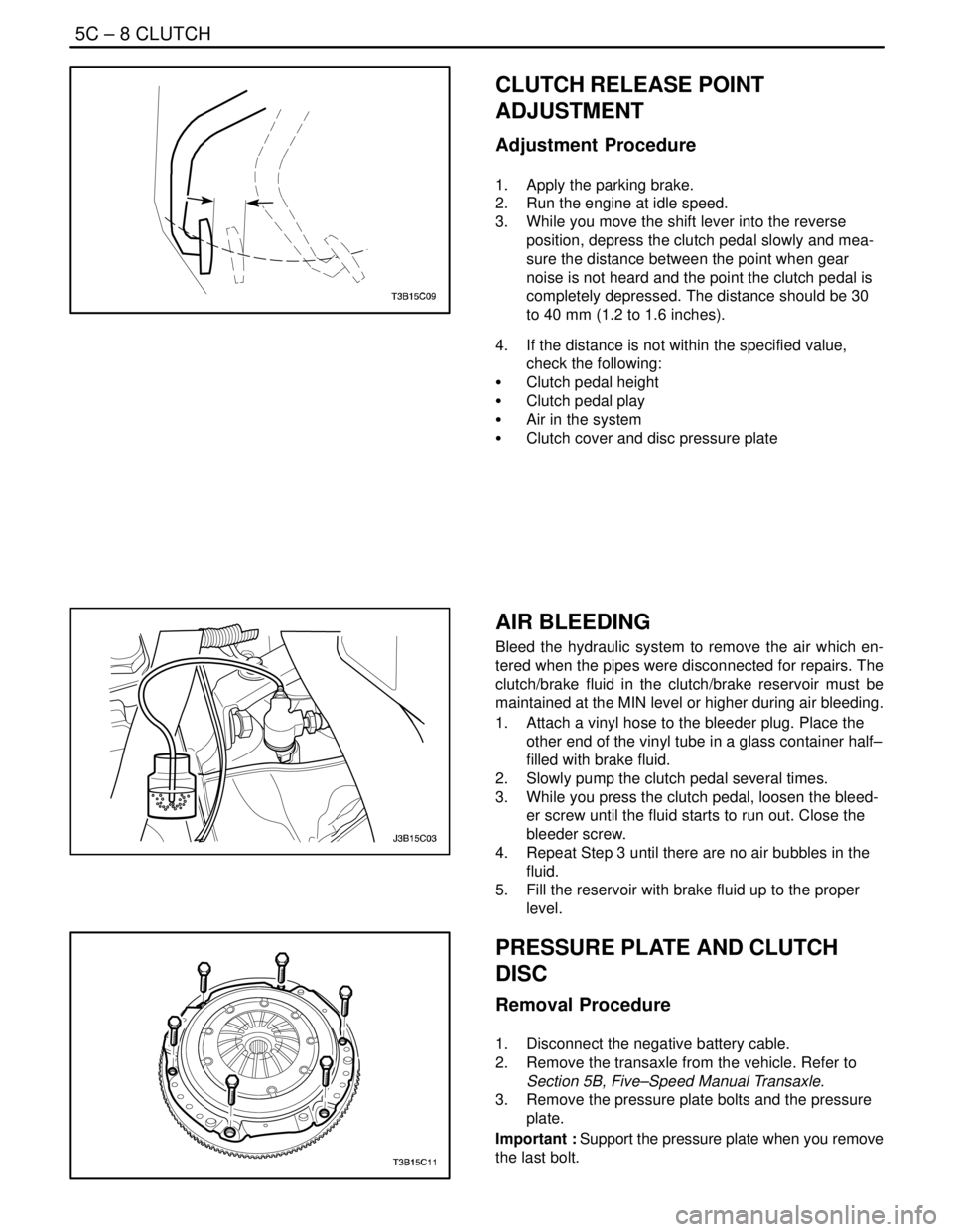
CLUTCH RELEASE POINT
ADJUSTMENT
Adjustment Procedure
1. Apply the parking brake.
2. Run the engine at idle speed.
3. While you move the shift lever into the reverse
position, depress the clutch pedal slowly and mea-
sure the distance between the point when gear
noise is not heard and the point the clutch pedal is
completely depressed. The distance should be 30
to 40 mm (1.2 to 1.6 inches).
4. If the distance is not within the specified value,
check the following:
S Clutch pedal height
S Clutch pedal play
S Air in the system
S Clutch cover and disc pressure plate
AIR BLEEDING
Bleed the hydraulic system to remove the air which en-
tered when the pipes were disconnected for repairs. The
clutch/brake fluid in the clutch/brake reservoir must be
maintained at the MIN level or higher during air bleeding.
1. Attach a vinyl hose to the bleeder plug. Place the
other end of the vinyl tube in a glass container half–
filled with brake fluid.
2. Slowly pump the clutch pedal several times.
3. While you press the clutch pedal, loosen the bleed-
er screw until the fluid starts to run out. Close the
bleeder screw.
4. Repeat Step 3 until there are no air bubbles in the
fluid.
5. Fill the reservoir with brake fluid up to the proper
level.
PRESSURE PLATE AND CLUTCH
DISC
Removal Procedure
1. Disconnect the negative battery cable.
2. Remove the transaxle from the vehicle. Refer to
Section 5B, Five–Speed Manual Transaxle.
3. Remove the pressure plate bolts and the pressure
plate.
Important : Support the pressure plate when you remove
the last bolt.
Page 1899 of 2643

5C – 12ICLUTCH
DAEWOO V–121 BL4
5. Install the push rod fixing pin and push rod.
6. Install the locking clip.
7. Bleed the air. Refer to ”Air Bleeding” in this section.
8. Adjust the clutch pedal. Refer to ”Clutch Pedal Ad-
justment” in this section.
9. Fill the reservoir with clutch/brake fluid up to the
proper level.
CONCENTRIC SLAVE CYLINDER
Removal Procedure
1. Remove the transaxle from the vehicle. Refer to
Section 5B, Five–Speed Manual Transaxle.
2. Remove the concentric slave cylinder retaining
bolts.
3. Disconnect the concentric slave cylinder pipe from
the concentric slave cylinder.
Notice : When removing the bushing, Make sure not to re-
move it with excessive force.
4. Remove the bushing from the concentric slave cyl-
inder pipe in the transaxle housing.
5. Remove the concentric slave cylinder pipe.
Notice : For removal or installation, Make sure not to sep-
arate oil seal fixing spring from the back side of the con-
centric slave cylinder.
6. Remove the O–ring and the concentric slave cylin-
der.
Page 1902 of 2643

SECTION : 6A
POWER STEERING SYSTEM
TABLE OF CONTENTS
SPECIFICATIONS6A–1 . . . . . . . . . . . . . . . . . . . . . . . . . .
Fastener Tightening Specifications 6A–1. . . . . . . . . . .
SPECIAL TOOLS6A–1 . . . . . . . . . . . . . . . . . . . . . . . . . . .
Special Tools Table 6A–1. . . . . . . . . . . . . . . . . . . . . . . .
DIAGNOSIS6A–2 . . . . . . . . . . . . . . . . . . . . . . . . . . . . . . . .
Power Steering System Pressure Test 6A–2. . . . . . . .
Power Steering System Leak Test 6A–2. . . . . . . . . . .
MAINTENANCE AND REPAIR6A–3 . . . . . . . . . . . . . . . ON–VEHICLE SERVICE 6A–3. . . . . . . . . . . . . . . . . . . . .
Bleeding the Power Steering System 6A–3. . . . . . . . .
Checking and Adding Fluid 6A–3. . . . . . . . . . . . . . . . . .
Fluid Reservoir 6A–4. . . . . . . . . . . . . . . . . . . . . . . . . . . .
Hoses and Pipes 6A–4. . . . . . . . . . . . . . . . . . . . . . . . . .
GENERAL DESCRIPTION AND SYSTEM
OPERATION6A–8 . . . . . . . . . . . . . . . . . . . . . . . . . . . . . .
Power Steering System 6A–8. . . . . . . . . . . . . . . . . . . . .
SPECIFICATIONS
FASTENER TIGHTENING SPECIFICATIONS
ApplicationNSmLb–FtLb–In
Power Steering Pump Pressure Line Fitting2821–
Return Line Clip Bolts8–71
Steering Gear Inlet and Outlet Pipe Fittings2821–
SPECIAL TOOLS
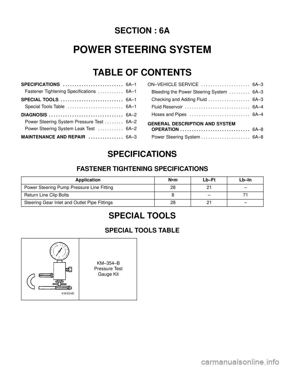
SPECIAL TOOLS TABLE
KM–354–B
Pressure Test
Gauge Kit
Page 1904 of 2643

POWER STEERING SYSTEM 6A – 3
DAEWOO V–121 BL4
MAINTENANCE AND REPAIR
ON–VEHICLE SERVICE
BLEEDING THE POWER STEERING
SYSTEM
If the power steering hydraulic system has been serviced,
an accurate fluid level reading cannot be obtained until the
air is bled from the system. Follow these steps to bleed the
air from the system.
1. Turn the wheels all the way to the left and add the
power steering fluid to the MIN mark on the fluid
level indicator.
Notice : When adding fluid or making a complete fluid
change, always use DEXRON®–II or III power steering
fluid. Failure to use the proper fluid will cause hose and
seal damage and fluid leaks.
2. Start the engine. With the engine running at fast
idle, recheck the fluid level. If necessary, add fluid
to bring the level up to the MIN mark.
3. Bleed the system by turning the wheels from side to
side without reaching the stop at either end. Keep
the fluid level at the MIN mark. The air must be
eliminated from the fluid before normal steering ac-
tion can be obtained.
4. Return the wheels to the center position. Continue
running the engine for 2 to 3 minutes.
5. Road test the car to be sure the steering functions
normally and is free from noise.
6. Recheck the fluid level as described in steps 1 and
2. Make sure the fluid level is at the MAX mark af-
ter the system has stabilized at its normal operating
temperature. Add fluid as needed.
CHECKING AND ADDING FLUID
Notice : When adding fluid or making a complete fluid
change, always use DEXRON®–II or III power steering
fluid. Failure to use the proper fluid will cause hose and
seal damage and fluid leaks.
1. The power steering fluid level is indicated either by
marks on a see–through fluid reservoir or by marks
on a fluid level indicator on the fluid reservoir cap.
2. If the fluid is warmed up to 66°C (150°F), the fluid
level should be between the MAX and MIN marks.
Add fluid as needed.
3. If the fluid is cool, 21°C (70°F), the fluid level
should be at the MIN mark. Add fluid as needed.