2004 DAEWOO LACETTI Ground
[x] Cancel search: GroundPage 91 of 2643
1C1 – 48I1.4L/1.6L DOHC ENGINE MECHANICAL
DAEWOO V–121 BL4
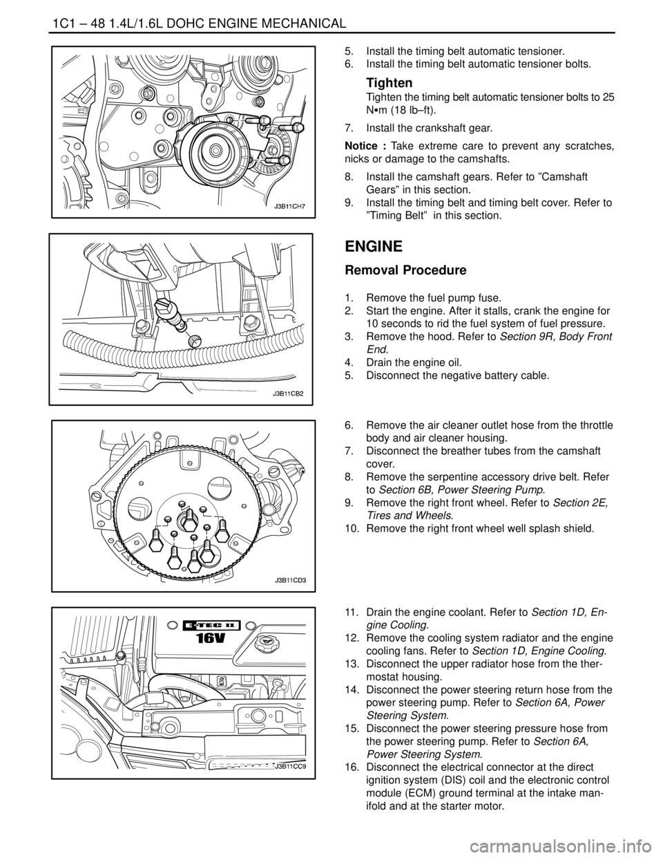
5. Install the timing belt automatic tensioner.
6. Install the timing belt automatic tensioner bolts.
Tighten
Tighten the timing belt automatic tensioner bolts to 25
NSm (18 lb–ft).
7. Install the crankshaft gear.
Notice : Take extreme care to prevent any scratches,
nicks or damage to the camshafts.
8. Install the camshaft gears. Refer to ”Camshaft
Gears” in this section.
9. Install the timing belt and timing belt cover. Refer to
”Timing Belt” in this section.
ENGINE
Removal Procedure
1. Remove the fuel pump fuse.
2. Start the engine. After it stalls, crank the engine for
10 seconds to rid the fuel system of fuel pressure.
3. Remove the hood. Refer to Section 9R, Body Front
End.
4. Drain the engine oil.
5. Disconnect the negative battery cable.
6. Remove the air cleaner outlet hose from the throttle
body and air cleaner housing.
7. Disconnect the breather tubes from the camshaft
cover.
8. Remove the serpentine accessory drive belt. Refer
to Section 6B, Power Steering Pump.
9. Remove the right front wheel. Refer to Section 2E,
Tires and Wheels.
10. Remove the right front wheel well splash shield.
11. Drain the engine coolant. Refer to Section 1D, En-
gine Cooling.
12. Remove the cooling system radiator and the engine
cooling fans. Refer to Section 1D, Engine Cooling.
13. Disconnect the upper radiator hose from the ther-
mostat housing.
14. Disconnect the power steering return hose from the
power steering pump. Refer to Section 6A, Power
Steering System.
15. Disconnect the power steering pressure hose from
the power steering pump. Refer to Section 6A,
Power Steering System.
16. Disconnect the electrical connector at the direct
ignition system (DIS) coil and the electronic control
module (ECM) ground terminal at the intake man-
ifold and at the starter motor.
Page 95 of 2643

1C1 – 52I1.4L/1.6L DOHC ENGINE MECHANICAL
DAEWOO V–121 BL4
18. Connect the power steering pressure hose.
19. Connect the power steering return hose.
20. Install the A/C compressor, if equipped. Refer to
Section 7B, Manual Control Heating, Ventilation,
and Air Conditioning Systems.
21. Install the generator. Refer to Section 1E, Engine
Electrical.
22. Install the serpentine accessory drive belt. Refer to
Section 6B, Power Steering Pump.
23. Install the right front wheel well splash shield.
24. Install the right front wheel. Refer to Section 2E,
Tires and Wheels.
25. Connect the fuel feed line to the fuel rail.
26. Connect all of the necessary vacuum lines, includ-
ing the brake booster vacuum hose.
27. Connect the O2 sensor connector, if equipped.
28. Connect the starter solenoid ”S” terminal wire and
power lead.
29. Connect the generator voltage regulator connector
and power lead.
30. Connect the CTS connector.
31. Connect the MAP, MAT sensor connectors.
32. Connect the TPS connector.
33. Install the electrical wiring harness clamp at the
intake manifold support bracket.
34. Connect the fuel injector harness connectors.
35. Connect the electrical connector at the DIS coil and
the ECM ground terminal at the starter.
36. Install the air cleaner outlet hose between the
throttle body and the air cleaner housing.
37. Connect the breather tubes to the camshaft cover.
38. Install the cooling system radiator and the engine
cooling fans. Refer to Section 1D, Engine Cooling.
Page 98 of 2643
1.4L/1.6L DOHC ENGINE MECHANICAL 1C1 – 55
DAEWOO V–121 BL4
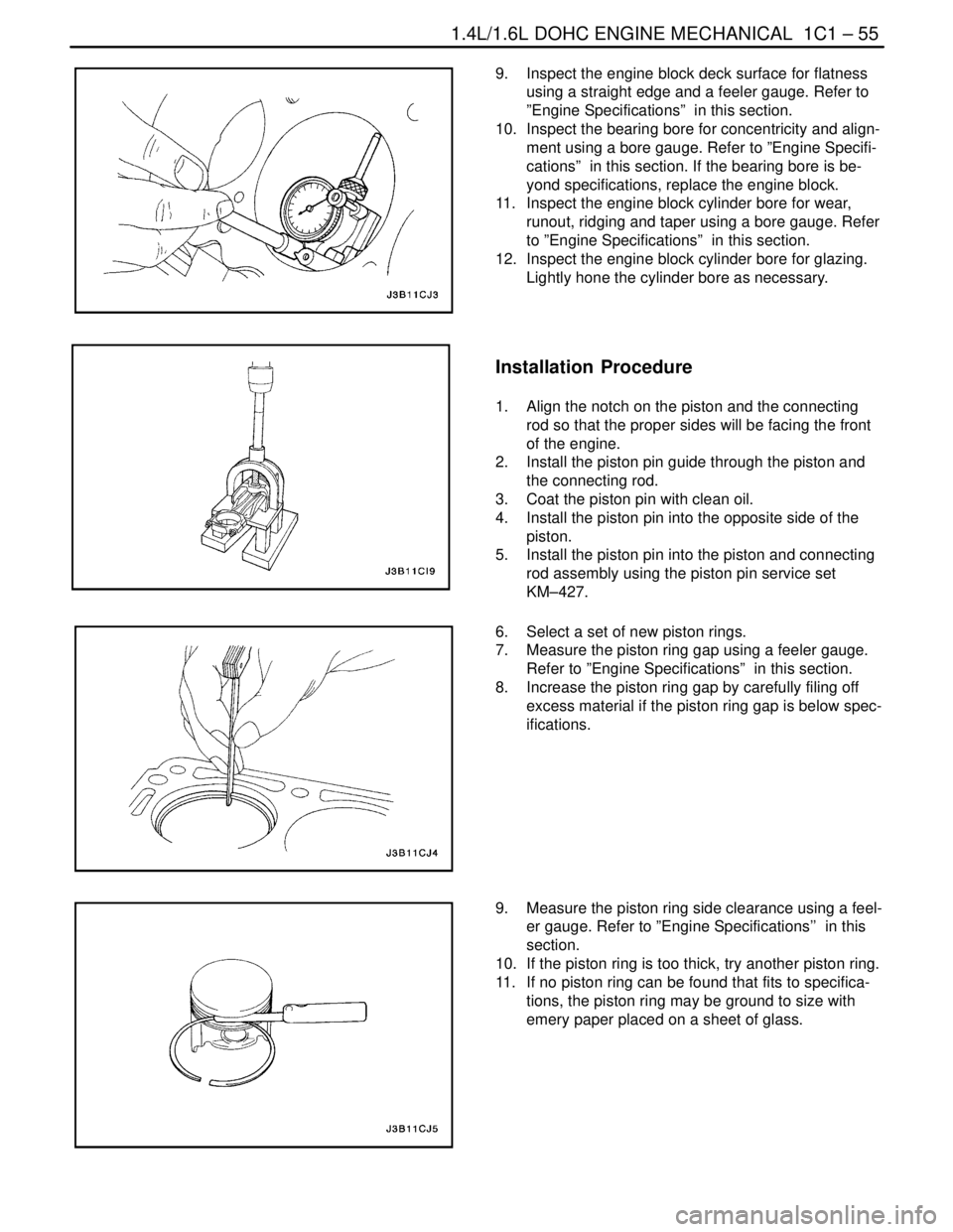
9. Inspect the engine block deck surface for flatness
using a straight edge and a feeler gauge. Refer to
”Engine Specifications” in this section.
10. Inspect the bearing bore for concentricity and align-
ment using a bore gauge. Refer to ”Engine Specifi-
cations” in this section. If the bearing bore is be-
yond specifications, replace the engine block.
11. Inspect the engine block cylinder bore for wear,
runout, ridging and taper using a bore gauge. Refer
to ”Engine Specifications” in this section.
12. Inspect the engine block cylinder bore for glazing.
Lightly hone the cylinder bore as necessary.
Installation Procedure
1. Align the notch on the piston and the connecting
rod so that the proper sides will be facing the front
of the engine.
2. Install the piston pin guide through the piston and
the connecting rod.
3. Coat the piston pin with clean oil.
4. Install the piston pin into the opposite side of the
piston.
5. Install the piston pin into the piston and connecting
rod assembly using the piston pin service set
KM–427.
6. Select a set of new piston rings.
7. Measure the piston ring gap using a feeler gauge.
Refer to ”Engine Specifications” in this section.
8. Increase the piston ring gap by carefully filing off
excess material if the piston ring gap is below spec-
ifications.
9. Measure the piston ring side clearance using a feel-
er gauge. Refer to ”Engine Specifications’’ in this
section.
10. If the piston ring is too thick, try another piston ring.
11. If no piston ring can be found that fits to specifica-
tions, the piston ring may be ground to size with
emery paper placed on a sheet of glass.
Page 105 of 2643
1C1 – 62I1.4L/1.6L DOHC ENGINE MECHANICAL
DAEWOO V–121 BL4
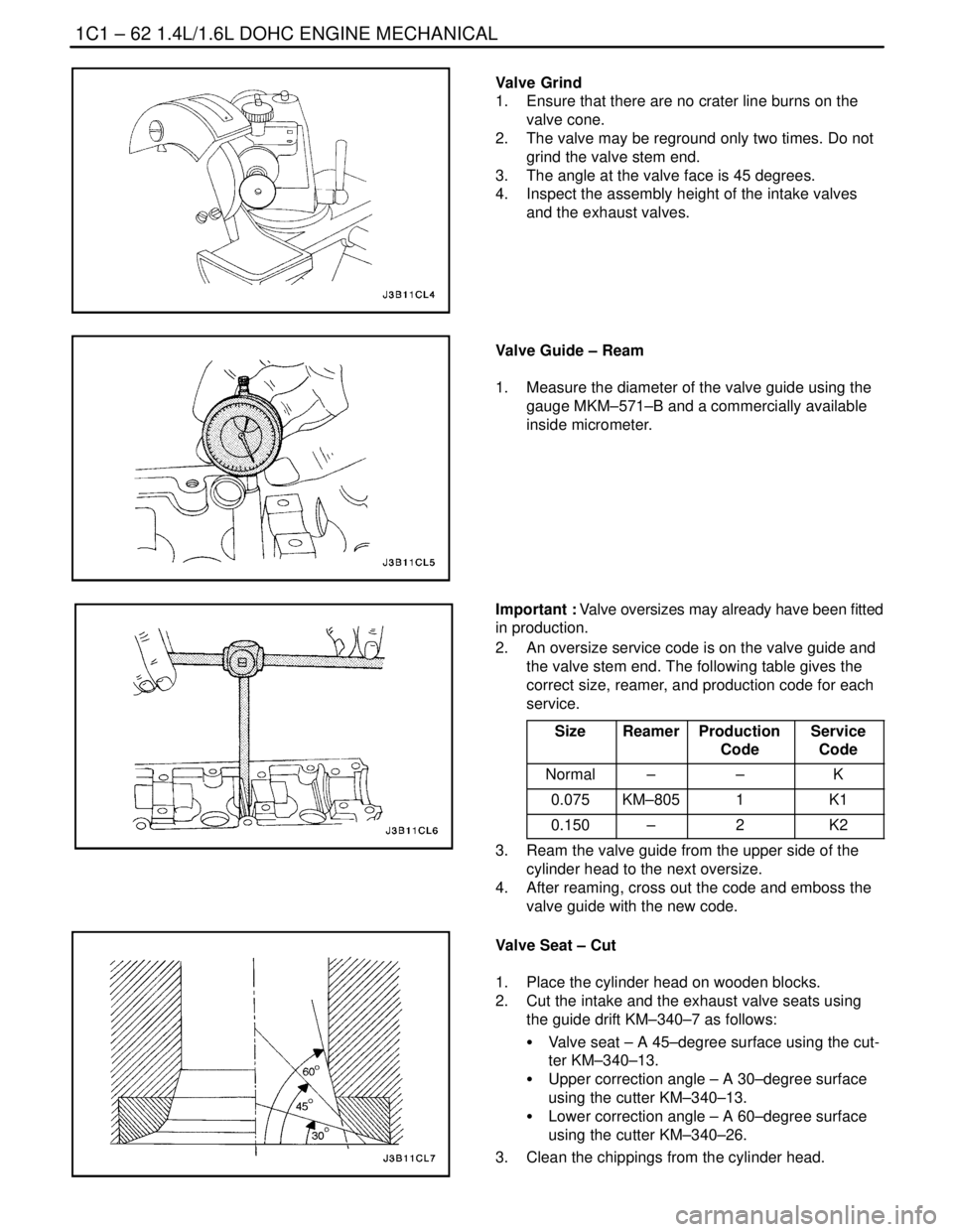
Valve Grind
1. Ensure that there are no crater line burns on the
valve cone.
2. The valve may be reground only two times. Do not
grind the valve stem end.
3. The angle at the valve face is 45 degrees.
4. Inspect the assembly height of the intake valves
and the exhaust valves.
Valve Guide – Ream
1. Measure the diameter of the valve guide using the
gauge MKM–571–B and a commercially available
inside micrometer.
Important : Valve oversizes may already have been fitted
in production.
2. An oversize service code is on the valve guide and
the valve stem end. The following table gives the
correct size, reamer, and production code for each
service.
Size
ReamerProduction
CodeService
Code
Normal––K
0.075KM–8051K1
0.150–2K2
3. Ream the valve guide from the upper side of the
cylinder head to the next oversize.
4. After reaming, cross out the code and emboss the
valve guide with the new code.
Valve Seat – Cut
1. Place the cylinder head on wooden blocks.
2. Cut the intake and the exhaust valve seats using
the guide drift KM–340–7 as follows:
S Valve seat – A 45–degree surface using the cut-
ter KM–340–13.
S Upper correction angle – A 30–degree surface
using the cutter KM–340–13.
S Lower correction angle – A 60–degree surface
using the cutter KM–340–26.
3. Clean the chippings from the cylinder head.
Page 133 of 2643
1.8L DOHC ENGINE MECHANICAL 1C2 – 13
DAEWOO V–121 BL4
Installation Procedure
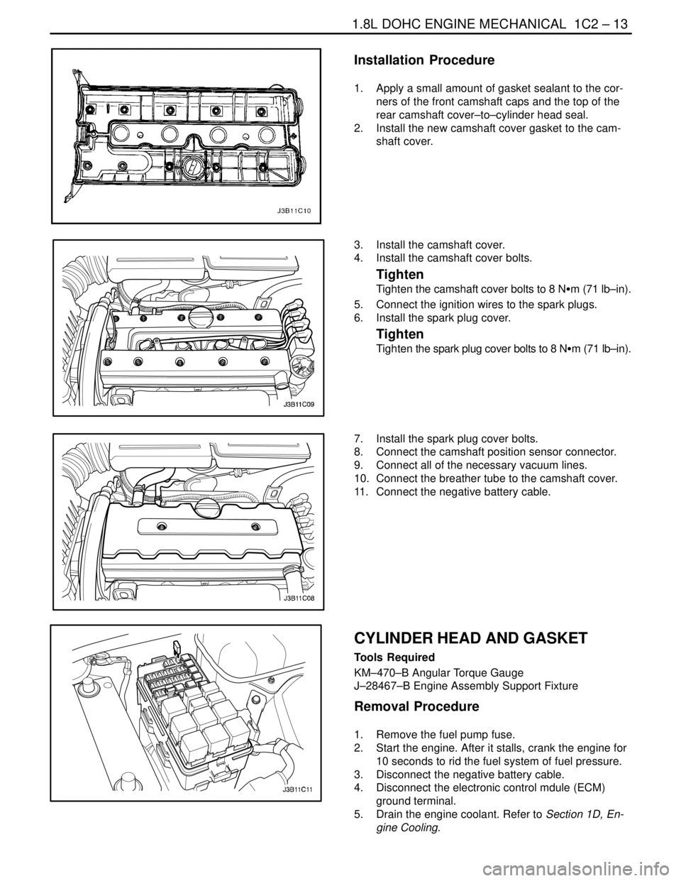
1. Apply a small amount of gasket sealant to the cor-
ners of the front camshaft caps and the top of the
rear camshaft cover–to–cylinder head seal.
2. Install the new camshaft cover gasket to the cam-
shaft cover.
3. Install the camshaft cover.
4. Install the camshaft cover bolts.
Tighten
Tighten the camshaft cover bolts to 8 NSm (71 lb–in).
5. Connect the ignition wires to the spark plugs.
6. Install the spark plug cover.
Tighten
Tighten the spark plug cover bolts to 8 NSm (71 lb–in).
7. Install the spark plug cover bolts.
8. Connect the camshaft position sensor connector.
9. Connect all of the necessary vacuum lines.
10. Connect the breather tube to the camshaft cover.
11. Connect the negative battery cable.
CYLINDER HEAD AND GASKET
Tools Required
KM–470–B Angular Torque Gauge
J–28467–B Engine Assembly Support Fixture
Removal Procedure
1. Remove the fuel pump fuse.
2. Start the engine. After it stalls, crank the engine for
10 seconds to rid the fuel system of fuel pressure.
3. Disconnect the negative battery cable.
4. Disconnect the electronic control mdule (ECM)
ground terminal.
5. Drain the engine coolant. Refer to Section 1D, En-
gine Cooling.
Page 142 of 2643

1C2 – 22I1.8L DOHC ENGINE MECHANICAL
DAEWOO V–121 BL4
56. Connect the CTS connector.
57. Connect the engine CTS connector.
58. Connect the IAC valve connector.
59. Connect the TPS connector.
60. Install the CCP and the EGR solenoid bracket bolt.
Tighten
Tighten the charcoal canister purge and exhaust gas
recirculation solenoid bracket bolt to 5 NSm (44 lb–in).
61. Connect the DIS coil connector.
62. Connect the O2 sensor connector, if equipped.
63. Connect the ECM ground terminal.
64. Install the fuel pump fuse.
65. Connect the negative battery ground cable.
66. Refill the engine cooling system. Refer to Section
1D, Engine Cooling.
CAMSHAFTS
Removal Procedure
1. Remove the timing belt. Refer to ”Timing Belt” in
this section.
2. Disconnect the breather tube at the camshaft cov-
er.
3. Disconnect the engine ventilation hose at the cam-
shaft cover.
4. Remove the spark plug cover bolts.
5. Remove the spark plug cover.
6. Disconnect the ignition wires from the spark plugs.
7. Remove the camshaft cover bolts.
8. Remove the camshaft cover washers.
9. Remove the camshaft cover and the camshaft cov-
er gasket.
Notice : Take extreme care to prevent any scratches,
nicks or damage to the camshafts.
10. While holding the intake camshaft firmly in place,
remove the intake camshaft gear bolt.
11. Remove the intake camshaft gear.
12. While holding the exhaust camshaft firmly in place,
remove the exhaust camshaft gear bolt.
13. Remove the exhaust camshaft gear.
Page 166 of 2643

1C2 – 46I1.8L DOHC ENGINE MECHANICAL
DAEWOO V–121 BL4
7. Install the timing belt automatic tensioner and bolt.
8. Install the camshaft gears. Refer to ”Camshaft
Gears” in this section.
9. Install the timing belt and timing belt cover. Refer to
”Timing Belt” in this section.
10. Connect the negative battery cable.
ENGINE
Removal Procedure
1. Remove the fuel pump fuse.
2. Start the engine. After it stalls, crank the engine for
10 seconds to rid the fuel system of fuel pressure.
3. Remove the hood. Refer to Section 9R, Body Front
End.
4. Drain the engine oil.
5. Disconnect the negative battery cable.
6. Discharge the air conditioning (A/C) system, if
equipped. Refer to Section 7B, Manual Control
Heating, Ventilation, and Air Conditioning Systems.
7. Disconnect the manifold air temperature (MAT)
sensor connector.
8. Remove the air cleaner outlet hose from the throttle
body and air cleaner housing.
9. Disconnect the breather tubes from the camshaft
cover.
10. Remove the right front wheel. Refer to Section 2E,
Tires and Wheels.
11. Remove the right front wheel well splash shield.
Refer to Section 9R, Body Font End.
12. Remove the serpentine accessory drive belt. Refer
to Section 6B, Power Steering Pump.
13. Drain the engine coolant. Refer to Section 1D, En-
gine Cooling.
14. Remove the cooling system radiator and the engine
cooling fans. Refer to Section 1D, Engine Cooling.
15. Disconnect the upper radiator hose from the ther-
mostat housing.
16. Disconnect the power steering return hose from the
power steering pump.
17. Disconnect the power steering pressure hose from
the power steering pump.
18. Disconnect the electrical connector at the direct
ignition system (DIS) coil and the electronic control
module (ECM) ground terminal and at the starter
motor.
Page 170 of 2643
1C2 – 50I1.8L DOHC ENGINE MECHANICAL
DAEWOO V–121 BL4
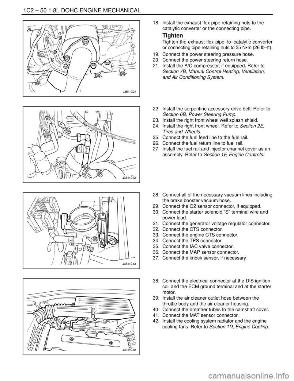
18. Install the exhaust flex pipe retaining nuts to the
catalytic converter or the connecting pipe.
Tighten
Tighten the exhaust flex pipe–to–catalytic converter
or connecting pipe retaining nuts to 35 NSm (26 lb–ft).
19. Connect the power steering pressure hose.
20. Connect the power steering return hose.
21. Install the A/C compressor, if equipped. Refer to
Section 7B, Manual Control Heating, Ventilation,
and Air Conditioning System.
22. Install the serpentine accessory drive belt. Refer to
Section 6B, Power Steering Pump.
23. Install the right front wheel well splash shield.
24. Install the right front wheel. Refer to Section 2E,
Tires and Wheels.
25. Connect the fuel feed line to the fuel rail.
26. Connect the fuel return line to fuel rail.
27. Install the fuel rail and injector channel cover as an
assembly. Refer to Section 1F, Engine Controls.
28. Connect all of the necessary vacuum lines including
the brake booster vacuum hose.
29. Connect the O2 sensor connector, if equipped.
30. Connect the starter solenoid ”S” terminal wire and
power lead.
31. Connect the generator voltage regulator connector.
32. Connect the CTS connector.
33. Connect the engine CTS connector.
34. Connect the TPS connector.
35. Connect the IAC valve connector.
36. Connect the MAP sensor connector.
37. Connect the knock sensor, if necessary
38. Connect the electrical connector at the DIS ignition
coil and the ECM ground terminal and at the starter
motor.
39. Install the air cleaner outlet hose between the
throttle body and the air cleaner housing.
40. Connect the breather tubes to the camshaft cover.
41. Connect the MAT sensor connector.
42. Install the cooling system radiator and the engine
cooling fans. Refer to Section 1D, Engine Cooling.