2004 DAEWOO LACETTI speed sensor
[x] Cancel search: speed sensorPage 952 of 2643

2D – 10IREAR SUSPENSION
DAEWOO V–121 BL4
Installation Procedure
1. Install the rear knuckle into the vehicle and install
the brake line into the strut assembly bracket.
2. Install the knuckle–to–strut assembly bolts and
nuts. Do not tighten.
3. Install the clip securing the brake line to the strut
assembly.
4. Tighten the knuckle–to–strut assembly nuts.
Tighten
Tighten the knuckle–to–strut assembly nuts to 100
NSm (74 lb–ft).
5. Connect the rear trailing link to the rear knuckle.
Refer to ”Rear Trailing Link” in this section.
6. Connect the rear parallel link to the knuckle. Refer
to ”Rear Parallel Link” in this section.
7. Connect the front parallel link to the knuckle. Refer
to ”Front Parallel Link” in this section.
8. Connect the parking brake to the knuckle assembly.
Refer to Section 4G, Parking Brake.
9. On vehicles equipped with rear drum brakes, con-
nect the brake line to the knuckle assembly. On
vehicles equipped with rear disc brakes, install the
rear brake caliper onto the knuckle assembly. Refer
to Section 4E1, Rear Disc Brakes.
10. On vehicles equipped with the antilock braking sys-
tem, install the ABS speed sensor. Refer to Section
4F, Antilock Brake System.
11. Install the wheel. Refer to Section 2E, Tires and
Wheels.
12. Lower the vehicle.
TRAILING LINK
Removal Procedure
1. Raise and suitably support the vehicle.
2. Remove the rear trailing link–to–rear knuckle nut.
3. Remove the rear trailing link–to–trailing link bracket
nut and the rear trailing link–to–knuckle bolt.
4. Remove the rear trailing link.
Page 956 of 2643

2D – 14IREAR SUSPENSION
DAEWOO V–121 BL4
Installation Procedure
1. Install the stabilizer shaft, the insulators, and the
stabilizer shaft clamps.
2. Install the stabilizer shaft–to–stabilizer link nut.
Tighten
Tighten the stabilizer shaft–to–stabilizer link nut to 47
NSm (35 lb–ft).
3. Install the stabilizer shaft clamp bolts.
Tighten
Tighten the stabilizer shaft clamp bolts to 40 NSm (30
lb–ft).
4. Lower the vehicle.
STABILIZER LINK
Removal Procedure
1. Raise and suitably support the vehicle.
2. Remove the wheel. Refer to Section 2E, Tires and
Wheels.
3. Remove the stabilizer shaft–to–stabilizer link nut.
4. Remove the stabilizer link–to–strut assembly nut.
5. Remove the stabilizer link.
Installation Procedure
1. Install the stabilizer link.
2. Install the stabilizer link–to–strut assembly nut.
Tighten
Tighten the stabilizer link–to–strut assembly nut to 47
NSm (35 lb–ft).
3. Install the stabilizer shaft–to–stabilizer link nut.
Tighten
Tighten the stabilizer shaft–to–stabilizer link nut to 47
NSm (35 lb–ft).
4. Install the wheel. Refer to Section 2E, Tires and
Wheels.
5. Lower the vehicle.
CROSSMEMBER
Removal Procedure
1. Raise and suitably support the vehicle.
2. Remove the front parallel link bolt from the cross-
member. Refer to ”Front Parallel Link” in this sec-
tion.
3. Remove the rear parallel link bolt from the cross-
member. Refer to ”Rear Parallel Link”in this section.
4. Remove the rear wheel speed sensor wiring from
the crossmember.
Page 957 of 2643

REAR SUSPENSION 2D – 15
DAEWOO V–121 BL4
5. Remove the crossmember–to–body bolts.
6. Remove the crossmember.
Installation Procedure
1. Install the crossmember.
2. Install the crossmember–to–body bolts.
Tighten
Tighten the crossmember–to–body bolts to 112 NSm
(83 lb–ft).
3. Route and install the rear wheel speed sensor wir-
ing.
4. Install the rear parallel link bolt onto the crossmem-
ber. Refer to ”Rear Parallel Link”in this section.
5. Install the front parallel link bolt onto the crossmem-
ber. Refer to ”Front Parallel Link” in this section.
6. Lower the vehicle.
HUB AND BEARING ASSEMBLY
Removal Procedure
1. Raise and suitably support the vehicle.
2. Remove the wheel. Refer to Section 2E, Tires and
Wheels.
3. On vehicles equipped with rear drum brakes, re-
move the rear brake drum detent screw and brake
drum. Refer to Section 4E2, Rear Drum Brakes.
4. On vehicles equipped with rear disc brakes, remove
the rear brake caliper and rear brake disc. Refer to
Section 4E1, Rear Disc Brakes.
5. Remove the hub bolts and hub assembly.
Page 1077 of 2643

4E2 – 8IREAR DRUM BRAKES
DAEWOO V–121 BL4
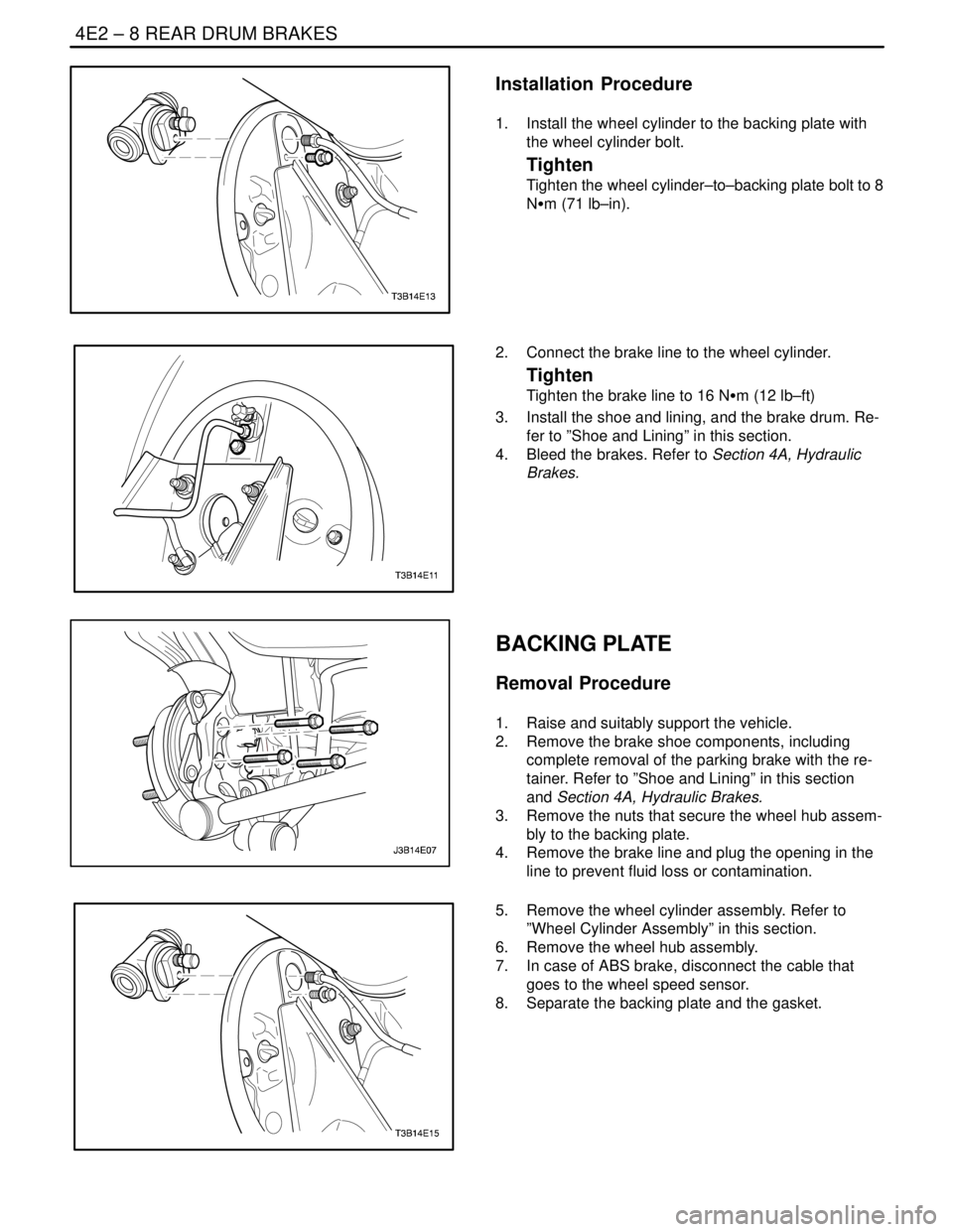
Installation Procedure
1. Install the wheel cylinder to the backing plate with
the wheel cylinder bolt.
Tighten
Tighten the wheel cylinder–to–backing plate bolt to 8
NSm (71 lb–in).
2. Connect the brake line to the wheel cylinder.
Tighten
Tighten the brake line to 16 NSm (12 lb–ft)
3. Install the shoe and lining, and the brake drum. Re-
fer to ”Shoe and Lining” in this section.
4. Bleed the brakes. Refer to Section 4A, Hydraulic
Brakes.
BACKING PLATE
Removal Procedure
1. Raise and suitably support the vehicle.
2. Remove the brake shoe components, including
complete removal of the parking brake with the re-
tainer. Refer to ”Shoe and Lining” in this section
and Section 4A, Hydraulic Brakes.
3. Remove the nuts that secure the wheel hub assem-
bly to the backing plate.
4. Remove the brake line and plug the opening in the
line to prevent fluid loss or contamination.
5. Remove the wheel cylinder assembly. Refer to
”Wheel Cylinder Assembly” in this section.
6. Remove the wheel hub assembly.
7. In case of ABS brake, disconnect the cable that
goes to the wheel speed sensor.
8. Separate the backing plate and the gasket.
Page 1082 of 2643

SECTION : 4F
ANTILOCK BRAKE SYSTEM
CAUTION : Disconnect the negative battery cable before removing or installing any electrical unit or when a tool
or equipment could easily come in contact with exposed electrical terminals. Disconnecting this cable will help
prevent personal injury and damage to the vehicle. The ignition must also be in LOCK unless otherwise noted.
TABLE OF CONTENTS
SPECIFICATIONS4F–2 . . . . . . . . . . . . . . . . . . . . . . . . . .
Fastener Tightening Specifications 4F–2. . . . . . . . . .
SPECIAL TOOLS4F–2 . . . . . . . . . . . . . . . . . . . . . . . . . . .
Special Tools Table 4F–2. . . . . . . . . . . . . . . . . . . . . . . .
SCHEMATIC AND ROUTING DIAGRAMS4F–3 . . . . .
Abs System Circuit (I) 4F–3. . . . . . . . . . . . . . . . . . . . . .
Abs System Circuit (II) 4F–4. . . . . . . . . . . . . . . . . . . . .
Ebcm Connector Face View 4F–5. . . . . . . . . . . . . . . . .
COMPONENT LOCATOR4F–6 . . . . . . . . . . . . . . . . . . . .
ABS/EBD System Drive 4F–6. . . . . . . . . . . . . . . . . . . .
DIAGNOSIS4F–7 . . . . . . . . . . . . . . . . . . . . . . . . . . . . . . . .
Diagnostic Circuit Check 4F–7. . . . . . . . . . . . . . . . . . .
ABS Indicator Lamp Inoperative 4F–9. . . . . . . . . . . . .
Power Supply to Control Module,
No DTCs Stored 4F–12. . . . . . . . . . . . . . . . . . . . . . . .
ABS Indicator Lamp Illuminated Continuously,
No DTCs Stored 4F–16. . . . . . . . . . . . . . . . . . . . . . . .
Electronic Brake–Force Distribution (EBD)
System Indicator Lamp Inoperative 4F–18. . . . . . . .
SELF–DIAGNOSTICS 4F–22. . . . . . . . . . . . . . . . . . . .
DISPLAYING DTCs 4F–22. . . . . . . . . . . . . . . . . . . . . . .
CLEARING DTCs 4F–22. . . . . . . . . . . . . . . . . . . . . . . .
INTERMITTENTS AND POOR
CONNECTIONS 4F–22. . . . . . . . . . . . . . . . . . . . . . . .
DTC C0035 Left Front Wheel Speed Sensor
Circuit Malfunction 4F–23. . . . . . . . . . . . . . . . . . . . . .
DTC C0040 Right Front Wheel Speed Sensor
Circuit Malfunction 4F–26. . . . . . . . . . . . . . . . . . . . . .
DTC C0045 Left Rear Wheel Speed Sensor
Circuit Malfunction 4F–29. . . . . . . . . . . . . . . . . . . . . .
DTC C0050 Right Rear Wheel Speed Sensor
Circuit Malfunction 4F–32. . . . . . . . . . . . . . . . . . . . . .
DTC C0060/C0065 Left Front Inlet and
Outlet Valve Solenoid Fault 4F–35. . . . . . . . . . . . . . .
DTC C0070/C0075 Right Front Inlet and
Outlet Valve Solenoid Fault 4F–37. . . . . . . . . . . . . . . DTC C0080/C0085 Left Rear Inlet and
Outlet Valve Solenoid Fault 4F–39. . . . . . . . . . . . . . .
DTC C0090/C0095 Right Rear Inlet and
Outlet Valve Solenoid Fault 4F–41. . . . . . . . . . . . . . .
DTC C0110 Pump Motor Circuit Malfunction 4F–43. .
DTC C0121 Valve Relay Circuit Malfunction 4F–45. .
DTC C0161 ABS Brake Switch Circuit
Malfunction 4F–47. . . . . . . . . . . . . . . . . . . . . . . . . . . .
DTC C0245 Wheel Speed Sensor Frequency
Error 4F–50. . . . . . . . . . . . . . . . . . . . . . . . . . . . . . . . . .
DTC C0550 ABS Control Module Internal
Fault 4F–54. . . . . . . . . . . . . . . . . . . . . . . . . . . . . . . . . .
DTC C0800 Low Voltage Fault 4F–56. . . . . . . . . . . . .
DTC C0931 Overheated 4F–59. . . . . . . . . . . . . . . . . . .
MAINTENANCE AND REPAIR4F–60 . . . . . . . . . . . . . .
ON–VEHICLE SERVICE 4F–60. . . . . . . . . . . . . . . . . . . .
Service Precautions 4F–60. . . . . . . . . . . . . . . . . . . . . . .
Bleeding System 4F–61. . . . . . . . . . . . . . . . . . . . . . . . .
ABS 5.3 Assembly 4F–61. . . . . . . . . . . . . . . . . . . . . . . .
Front Wheel Speed Sensor 4F–62. . . . . . . . . . . . . . . .
Front Wheel Speed Sensor Jumper Harness 4F–63.
Rear Wheel Speed Sensor 4F–64. . . . . . . . . . . . . . . . .
GENERAL DESCRIPTION AND SYSTEM
OPERATION4F–65 . . . . . . . . . . . . . . . . . . . . . . . . . . . . .
Basic Knowledge Required 4F–65. . . . . . . . . . . . . . . . .
ABS System Components 4F–65. . . . . . . . . . . . . . . . .
Base Braking Mode 4F–65. . . . . . . . . . . . . . . . . . . . . . .
Antilock Braking Mode 4F–66. . . . . . . . . . . . . . . . . . . . .
EBD System 4F–69. . . . . . . . . . . . . . . . . . . . . . . . . . . . .
Electronic Brake–Force Distribution (EBD) Failure
Matrix 4F–70. . . . . . . . . . . . . . . . . . . . . . . . . . . . . . . . .
Tires and ABS/EBD 4F–71. . . . . . . . . . . . . . . . . . . . . . .
Electronic Brake Control Module (EBCM) 4F–71. . . .
Front Wheel Speed Sensors 4F–71. . . . . . . . . . . . . . .
Front Wheel Speed Sensor Rings 4F–71. . . . . . . . . . .
Rear Wheel Speed Sensors and Rings 4F–71. . . . . .
Valve Relay and Pump Motor Relay 4F–71. . . . . . . . .
Page 1083 of 2643

4F – 2IANTILOCK BRAKE SYSTEM
DAEWOO V–121 BL4
Wiring Harness 4F–71. . . . . . . . . . . . . . . . . . . . . . . . . . . Indicators 4F–71. . . . . . . . . . . . . . . . . . . . . . . . . . . . . . . .
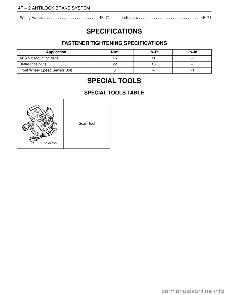
SPECIFICATIONS
FASTENER TIGHTENING SPECIFICATIONS
ApplicationNSmLb–FtLb–In
ABS 5.3 Mounting Nuts1511–
Brake Pipe Nuts2216–
Front Wheel Speed Sensor Bolt8–71
SPECIAL TOOLS
SPECIAL TOOLS TABLE
Scan Tool
Page 1084 of 2643

ANTILOCK BRAKE SYSTEM 4F – 3
DAEWOO V–121 BL4
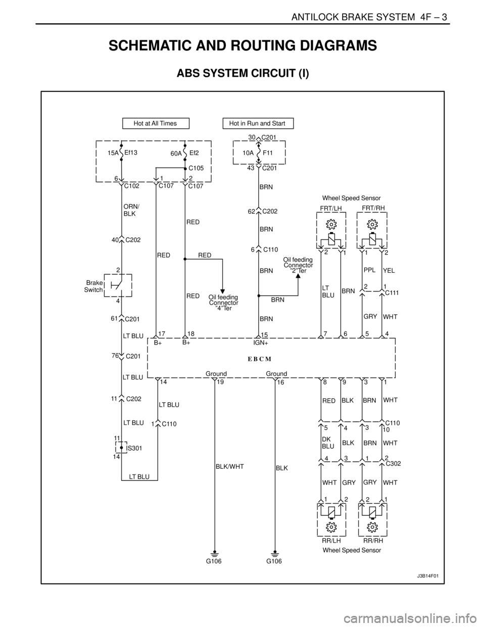
SCHEMATIC AND ROUTING DIAGRAMS
ABS SYSTEM CIRCUIT (I)
1
12
2
C111 1 2 2
E B C M
19
16 1418
B+
B+1576 54
G106
10A
62C202 BRN
BRN
BRN
BRN
BRNF11
Hot in Run and Start
6C110 C107 C107
40 C202
60A
1
6C105
C102
RED ORN/
BLK
RED RED
RED
Ground IGN+
Ground LT B L U Brake
Switch2
4Ef215AEf13
Hot at All Times
4330
C201 C201
J3B14F01
11
11
S301
2 WHT GRYGRY
WHT GRY
WHT PPL
YEL
WHTWHT
RED
BRN BRN
BLK BLK
DK
BLUBRN LT
BLU
1
21 4 5
10 89 3
31
C110
43
12
C30214C202
LT B L U LT B L U LT B L U
LT B L U
RR/LH
Wheel Speed SensorRR/RH BLK/WHT
G106
BLK
61
C201
76
C201
17
Oil feeding
Connector
”2”Ter
Oil feeding
Connector
”4”Ter
FRT/LHWheel Speed Sensor
FRT/RH
1C110
Page 1087 of 2643

4F – 6IANTILOCK BRAKE SYSTEM
DAEWOO V–121 BL4
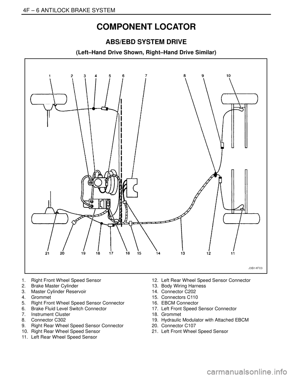
COMPONENT LOCATOR
ABS/EBD SYSTEM DRIVE
(Left–Hand Drive Shown, Right–Hand Drive Similar)
1. Right Front Wheel Speed Sensor
2. Brake Master Cylinder
3. Master Cylinder Reservoir
4. Grommet
5. Right Front Wheel Speed Sensor Connector
6. Brake Fluid Level Switch Connector
7. Instrument Cluster
8. Connector C302
9. Right Rear Wheel Speed Sensor Connector
10. Right Rear Wheel Speed Sensor
11. Left Rear Wheel Speed Sensor12. Left Rear Wheel Speed Sensor Connector
13. Body Wiring Harness
14. Connector C202
15. Connectors C110
16. EBCM Connector
17. Left Front Speed Sensor Connector
18. Grommet
19. Hydraulic Modulator with Attached EBCM
20. Connector C107
21. Left Front Wheel Speed Sensor