2004 CHRYSLER VOYAGER radio
[x] Cancel search: radioPage 1241 of 2585
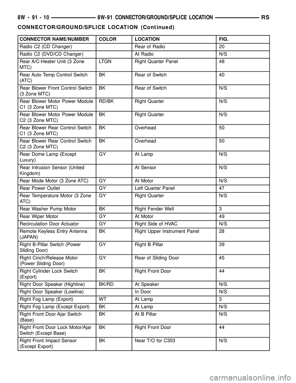
CONNECTOR NAME/NUMBER COLOR LOCATION FIG.
Radio C2 (CD Changer) Rear of Radio 20
Radio C2 (DVD/CD Changer) At Radio N/S
Rear A/C-Heater Unit (3 Zone
MTC)LTGN Right Quarter Panel 48
Rear Auto Temp Control Switch
(ATC)BK Rear of Switch 40
Rear Blower Front Control Switch
(3 Zone MTC)BK Rear of Switch N/S
Rear Blower Motor Power Module
C1 (3 Zone MTC)RD/BK Right Quarter N/S
Rear Blower Motor Power Module
C2 (3 Zone MTC)BK Right Quarter N/S
Rear Blower Rear Control Switch
C1 (3 Zone MTC)BK Overhead 50
Rear Blower Rear Control Switch
C2 (3 Zone MTC)BK Overhead 50
Rear Dome Lamp (Except
Luxury)GY At Lamp N/S
Rear Intrusion Sensor (United
Kingdom)At Sensor N/S
Rear Mode Motor (3 Zone ATC) GY At Motor N/S
Rear Power Outlet GY Left Quarter Panel 47
Rear Temperature Motor (3 Zone
ATC)GY Right Quarter N/S
Rear Washer Pump Motor BK Right Fender Well 3
Rear Wiper Motor GY At Motor 49
Recirculation Door Actuator GY Right Side of HVAC N/S
Remote Keyless Entry Antenna
(JAPAN)BK Right Upper Instrument Panel 28
Right B-Pillar Switch (Power
Sliding Door)GY Right B Pillar 39
Right Cinch/Release Motor
(Power Sliding Door)GY Rear of Sliding Door 45
Right Cylinder Lock Switch
(Export)BK Right Front Door 44
Right Door Speaker (Highline) BK/RD At Speaker N/S
Right Door Speaker (Lowline) In Door N/S
Right Fog Lamp (Export) WT At Lamp 3
Right Fog Lamp (Except Export) BK At Lamp N/S
Right Front Door Ajar Switch
(Base)BK At B Pillar N/S
Right Front Door Lock Motor/Ajar
Switch (Except Base)BK Right Front Door 44
Right Front Impact Sensor
(Except Export)BK Near T/O for C303 N/S
8W - 91 - 10 8W-91 CONNECTOR/GROUND/SPLICE LOCATIONRS
CONNECTOR/GROUND/SPLICE LOCATION (Continued)
Page 1242 of 2585
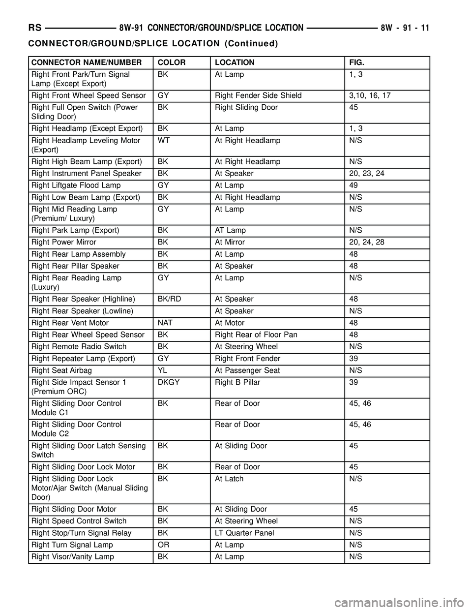
CONNECTOR NAME/NUMBER COLOR LOCATION FIG.
Right Front Park/Turn Signal
Lamp (Except Export)BK At Lamp 1, 3
Right Front Wheel Speed Sensor GY Right Fender Side Shield 3,10, 16, 17
Right Full Open Switch (Power
Sliding Door)BK Right Sliding Door 45
Right Headlamp (Except Export) BK At Lamp 1, 3
Right Headlamp Leveling Motor
(Export)WT At Right Headlamp N/S
Right High Beam Lamp (Export) BK At Right Headlamp N/S
Right Instrument Panel Speaker BK At Speaker 20, 23, 24
Right Liftgate Flood Lamp GY At Lamp 49
Right Low Beam Lamp (Export) BK At Right Headlamp N/S
Right Mid Reading Lamp
(Premium/ Luxury)GY At Lamp N/S
Right Park Lamp (Export) BK AT Lamp N/S
Right Power Mirror BK At Mirror 20, 24, 28
Right Rear Lamp Assembly BK At Lamp 48
Right Rear Pillar Speaker BK At Speaker 48
Right Rear Reading Lamp
(Luxury)GY At Lamp N/S
Right Rear Speaker (Highline) BK/RD At Speaker 48
Right Rear Speaker (Lowline) At Speaker N/S
Right Rear Vent Motor NAT At Motor 48
Right Rear Wheel Speed Sensor BK Right Rear of Floor Pan 48
Right Remote Radio Switch BK At Steering Wheel N/S
Right Repeater Lamp (Export) GY Right Front Fender 39
Right Seat Airbag YL At Passenger Seat N/S
Right Side Impact Sensor 1
(Premium ORC)DKGY Right B Pillar 39
Right Sliding Door Control
Module C1BK Rear of Door 45, 46
Right Sliding Door Control
Module C2Rear of Door 45, 46
Right Sliding Door Latch Sensing
SwitchBK At Sliding Door 45
Right Sliding Door Lock Motor BK Rear of Door 45
Right Sliding Door Lock
Motor/Ajar Switch (Manual Sliding
Door)BK At Latch N/S
Right Sliding Door Motor BK At Sliding Door 45
Right Speed Control Switch BK At Steering Wheel N/S
Right Stop/Turn Signal Relay BK LT Quarter Panel N/S
Right Turn Signal Lamp OR At Lamp N/S
Right Visor/Vanity Lamp BK At Lamp N/S
RS8W-91 CONNECTOR/GROUND/SPLICE LOCATION8W-91-11
CONNECTOR/GROUND/SPLICE LOCATION (Continued)
Page 1243 of 2585
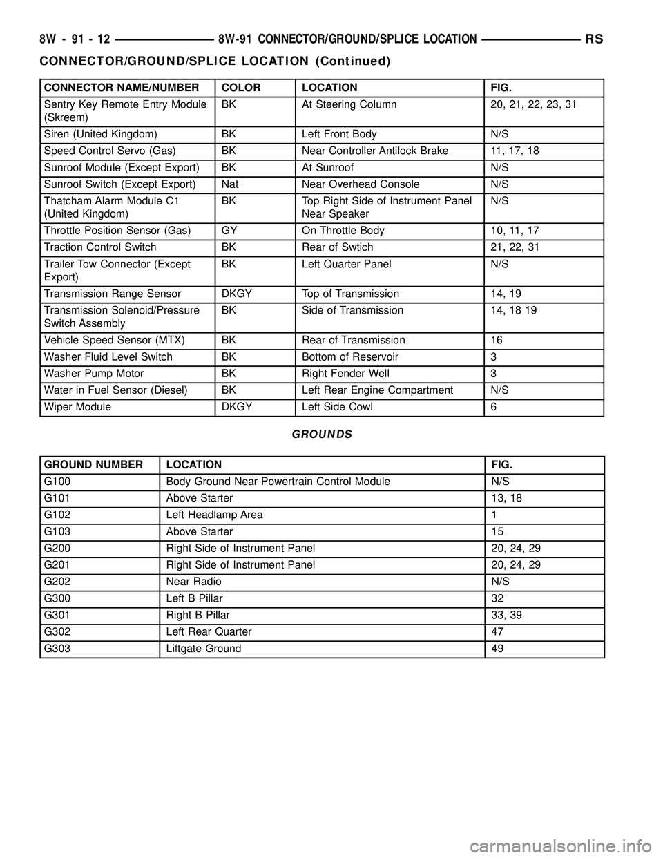
CONNECTOR NAME/NUMBER COLOR LOCATION FIG.
Sentry Key Remote Entry Module
(Skreem)BK At Steering Column 20, 21, 22, 23, 31
Siren (United Kingdom) BK Left Front Body N/S
Speed Control Servo (Gas) BK Near Controller Antilock Brake 11, 17, 18
Sunroof Module (Except Export) BK At Sunroof N/S
Sunroof Switch (Except Export) Nat Near Overhead Console N/S
Thatcham Alarm Module C1
(United Kingdom)BK Top Right Side of Instrument Panel
Near SpeakerN/S
Throttle Position Sensor (Gas) GY On Throttle Body 10, 11, 17
Traction Control Switch BK Rear of Swtich 21, 22, 31
Trailer Tow Connector (Except
Export)BK Left Quarter Panel N/S
Transmission Range Sensor DKGY Top of Transmission 14, 19
Transmission Solenoid/Pressure
Switch AssemblyBK Side of Transmission 14, 18 19
Vehicle Speed Sensor (MTX) BK Rear of Transmission 16
Washer Fluid Level Switch BK Bottom of Reservoir 3
Washer Pump Motor BK Right Fender Well 3
Water in Fuel Sensor (Diesel) BK Left Rear Engine Compartment N/S
Wiper Module DKGY Left Side Cowl 6
GROUNDS
GROUND NUMBER LOCATION FIG.
G100 Body Ground Near Powertrain Control Module N/S
G101 Above Starter 13, 18
G102 Left Headlamp Area 1
G103 Above Starter 15
G200 Right Side of Instrument Panel 20, 24, 29
G201 Right Side of Instrument Panel 20, 24, 29
G202 Near Radio N/S
G300 Left B Pillar 32
G301 Right B Pillar 33, 39
G302 Left Rear Quarter 47
G303 Liftgate Ground 49
8W - 91 - 12 8W-91 CONNECTOR/GROUND/SPLICE LOCATIONRS
CONNECTOR/GROUND/SPLICE LOCATION (Continued)
Page 1568 of 2585
SHROUD - UPPER
REMOVAL
(1) Remove the two shroud-to-shroud mounting
screws from the lower shroud (Fig. 32).
(2) Unsnap the upper shroud from the lower on
the left side as follows:
(a) Hook a finger on the left hand around the
rear of the shrouds at the seam (Fig. 33), near the
snap points.
(b) Grasp the upper shroud at the rear using the
right hand (Fig. 33).
(c) As the left hand's hooked finger is pulled out-
ward against the seam, pull the upper shroud
upward using the right hand, disconnecting the
shroud snaps.
(3) Unsnap the upper shroud from the lower on
the right side as follows:
(a) Hook a finger on the right hand around the
rear of the shrouds at the seam (Fig. 34), near the
snap points.
(b) Grasp the upper shroud at the rear using the
left hand (Fig. 34).
(c) As the right hand's hooked finger is pulled
outward against the seam, pull the upper shroud
upward using the left hand, disconnecting the
shroud snaps.
(4) Lift the upper shroud straight up off the steer-
ing column. If vehicle is equipped with traction con-
trol, disconnect wiring connector at traction control
switch pig tail. If vehicle is equipped with power fold-
away mirrors (Export), disconnect wiring connector
at mirror switch pig tail. Remove upper shroud.
(5) If vehicle is equipped with traction control,
remove traction control switch from shroud.
(6) If vehicle is equipped with power foldaway mir-
rors (Export), remove power fold-away switch from
upper shroud.
INSTALLATION
(1) If the vehicle is equipped with power foldaway
mirrors (Export), install the power fold-away switch
in the upper shroud.
(2) If vehicle is equipped with traction control,
install the traction control switch in the upper
shroud.
(3) Place the upper shroud over the lower shroud,
aligning the snap clips and alignment tabs. If the
vehicle is equipped with traction control, connect the
wiring connector at the traction control switch pig
tail before lining the shrouds up to one another.
(4) Snap the upper shroud to the lower shroud.
Once snapped into place, verify there are no gaps
between the two mating surfaces of the shrouds.(5) Install the two shroud-to-shroud mounting
screws (Fig. 32). Tighten the screws to 2 N´m (17 in.
lbs.) torque.
(6) Ensure that the shrouds are snug and fit is
acceptable.
STEERING WHEEL
REMOVAL
NOTE: Before proceeding, (Refer to 19 - STEERING/
COLUMN - WARNING)(Refer to 8 - ELECTRICAL/RE-
STRAINTS - WARNING).
(1) Adjust the steering wheel so that the tires are
in thestraight-aheadposition.
(2) Disconnect and isolate the battery negative
cable.
(3) Remove the two bolts from the rear of the
steering wheel attaching the driver airbag. Lift the
airbag from the steering wheel.
(4) Disconnect airbag squib wiring connectors from
the airbag and the horn/speed control switch pigtail
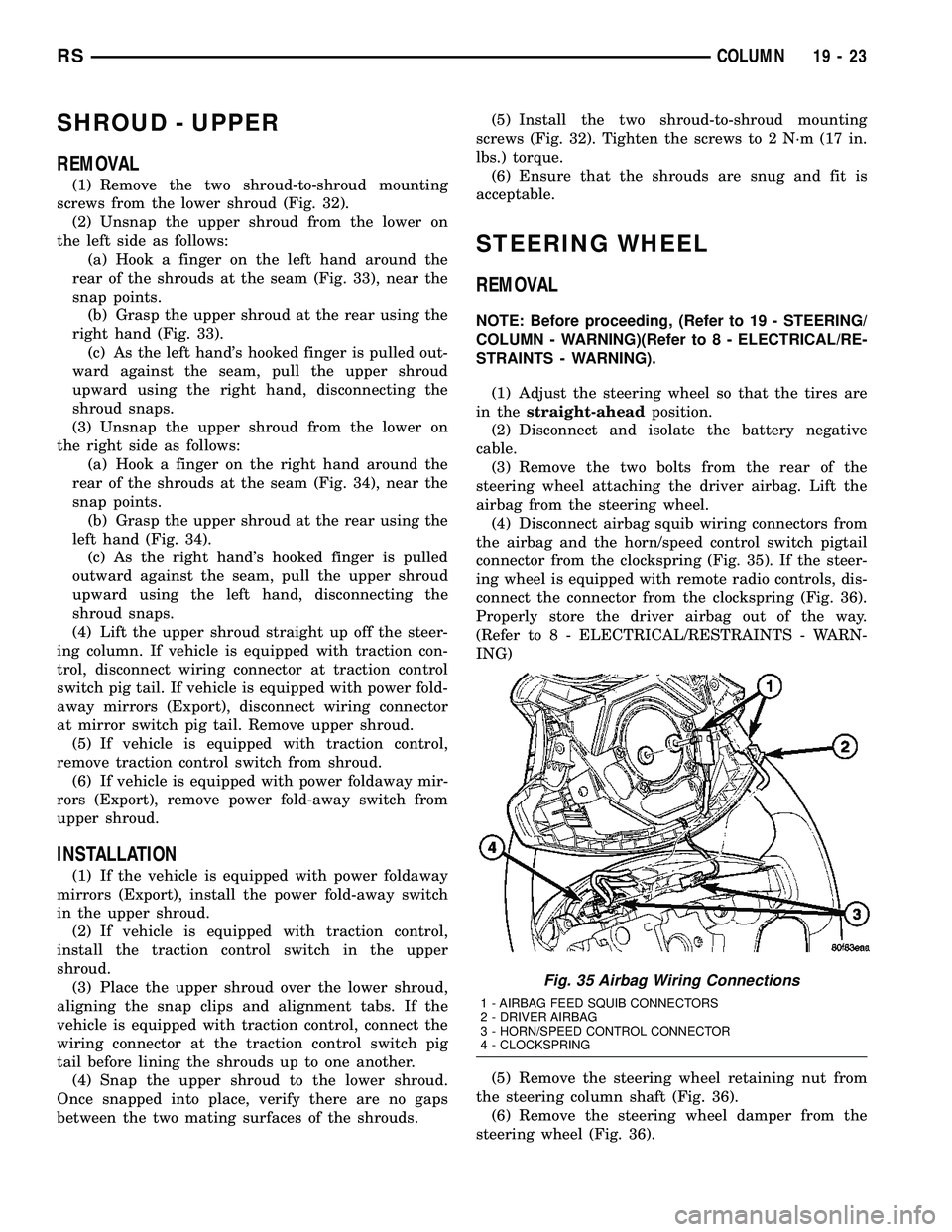
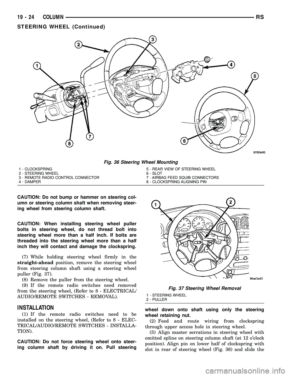
connector from the clockspring (Fig. 35). If the steer-
ing wheel is equipped with remote radio controls, dis-
connect the connector from the clockspring (Fig. 36).
Properly store the driver airbag out of the way.
(Refer to 8 - ELECTRICAL/RESTRAINTS - WARN-
ING)
(5) Remove the steering wheel retaining nut from
the steering column shaft (Fig. 36).
(6) Remove the steering wheel damper from the
steering wheel (Fig. 36).
Fig. 35 Airbag Wiring Connections
1 - AIRBAG FEED SQUIB CONNECTORS
2 - DRIVER AIRBAG
3 - HORN/SPEED CONTROL CONNECTOR
4 - CLOCKSPRING
RSCOLUMN19-23
Page 1569 of 2585
CAUTION: Do not bump or hammer on steering col-
umn or steering column shaft when removing steer-
ing wheel from steering column shaft.
CAUTION: When installing steering wheel puller
bolts in steering wheel, do not thread bolt into
steering wheel more than a half inch. If bolts are
threaded into the steering wheel more than a half
inch they will contact and damage the clockspring.
(7) While holding steering wheel firmly in the
straight-aheadposition, remove the steering wheel
from steering column shaft using a steering wheel
puller (Fig. 37).
(8) Remove the puller from the steering wheel.
(9) If the remote radio switches need removed
from the steering wheel, (Refer to 8 - ELECTRICAL/
AUDIO/REMOTE SWITCHES - REMOVAL).
INSTALLATION
(1) If the remote radio switches need to be
installed on the steering wheel, (Refer to 8 - ELEC-
TRICAL/AUDIO/REMOTE SWITCHES - INSTALLA-
TION).
CAUTION: Do not force steering wheel onto steer-
ing column shaft by driving it on. Pull steeringwheel down onto shaft using only the steering
wheel retaining nut.
(2) Feed and route wiring from clockspring
through upper access hole in steering wheel.
(3) Align master serrations in steering wheel with
omitted spline on steering column shaft (at 12 o'clock
position). Align pin on lower half of clockspring with
slot in rear of steering wheel (Fig. 36) and slide the
Fig. 36 Steering Wheel Mounting
1 - CLOCKSPRING
2 - STEERING WHEEL
3 - REMOTE RADIO CONTROL CONNECTOR
4 - DAMPER5 - REAR VIEW OF STEERING WHEEL
6 - SLOT
7 - AIRBAG FEED SQUIB CONNECTORS
8 - CLOCKSPRING ALIGNING PIN
Fig. 37 Steering Wheel Removal
1 - STEERING WHEEL
2 - PULLER
19 - 24 COLUMNRS
STEERING WHEEL (Continued)
Page 1570 of 2585

steering wheel onto the steering column shaft by
hand. Use care not to pinch any wiring.
NOTE: Before installing the damper on the steering
wheel, inspect the damper to ensure the rubber iso-
lator on the damper is not deteriorated or damaged.
If the damper is installed with a damaged isolator, a
buzz, squeak or rattle condition may develop.
(4) Install the steering wheel damper on the steer-
ing wheel (Fig. 36).
(5) Install the steering wheel retaining nut.
Tighten the steering wheel retaining nut to 61 N´m
(45 ft. lbs.) torque.(6) If the steering wheel is equipped with remote
radio controls, connect the wiring connector to the
clockspring (Fig. 36).
(7) Connect the airbag squib wiring connectors to
the airbag and the horn/speed control switch pigtail
connector to the clockspring (Fig. 35).
(8) Install the driver airbag in the steering wheel.
Install and tighten the airbag attaching bolts to 10
N´m (90 in. lbs.) torque.
(9) To properly connect the battery and test the
airbag system, (Refer to 8 - ELECTRICAL/RE-
STRAINTS - DIAGNOSIS AND TESTING).
RSCOLUMN19-25
STEERING WHEEL (Continued)
Page 2088 of 2585
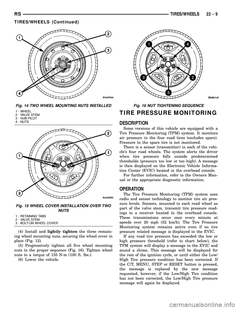
(4) Install andlightly tightenthe three remain-
ing wheel mounting nuts, securing the wheel cover in
place (Fig. 12).
(5) Progressively tighten all five wheel mounting
nuts in the proper sequence (Fig. 16). Tighten wheel
nuts to a torque of 135 N´m (100 ft. lbs.).
(6) Lower the vehicle.
TIRE PRESSURE MONITORING
DESCRIPTION
Some versions of this vehicle are equipped with a
Tire Pressure Monitoring (TPM) system. It monitors
air pressure in the four road tires (excludes spare).
Pressure in the spare tire is not monitored.
There is a sensor (transmitter) in each of the vehi-
cle's four road wheels. The system alerts the driver
when tire pressure falls outside predetermined
thresholds (pressure too low or too high). A message
is then displayed on the Electronic Vehicle Informa-
tion Center (EVIC) located in the overhead console.
For further information, refer to the Owners Man-
ual or the appropriate diagnostic information.
OPERATION
The Tire Pressure Monitoring (TPM) system uses
radio and sensor technology to monitor tire air pres-
sure levels. Sensors, mounted to each road wheel as
part of the valve stem, transmit tire pressure read-
ings to a receiver located in the overhead console.
These transmissions occur once every minute at
speeds over 20 mph (32 km/h). The Tire Pressure
Monitoring system remains active even if no tire
pressure related message is displayed in the EVIC.
If any road tire pressure has exceeded the low or
high pressure threshold (refer to chart below), the
TPM system will display a message in the EVIC and
sound a chime. This message will be displayed for
the rest of the ignition cycle, or until either the Low/
High Tire pressure condition has been corrected. If
the C/T, MENU, STEP or RESET button is pressed,
the message is replaced by the new message
requested; however, if the Low/High Tire condition
has not been corrected, the Low/High Tire pressure
message will again be displayed.
Fig. 14 TWO WHEEL MOUNTING NUTS INSTALLED
1 - WHEEL
2 - VALVE STEM
3 - HUB PILOT
4 - NUTS
Fig. 15 WHEEL COVER INSTALLATION OVER TWO
NUTS
1 - RETAINING TABS
2 - VALVE STEM
3 - BOLT-ON WHEEL COVER
Fig. 16 NUT TIGHTENING SEQUENCE
RSTIRES/WHEELS22-9
TIRES/WHEELS (Continued)
Page 2102 of 2585
TIRES/WHEELS
TABLE OF CONTENTS
page page
TIRE PRESSURE MONITORING............... 1TIRES................................... 5
TIRE PRESSURE MONITORING
TABLE OF CONTENTS
page page
TIRE PRESSURE MONITORING DESCRIPTION ..........................1
OPERATION ............................1
SENSOR - TPM DESCRIPTION ..........................1
OPERATION ............................2
CAUTION ..............................2 DIAGNOSIS AND TESTING - TIRE PRESSURE
SENSOR .............................2
STANDARD PROCEDURE - TIRE PRESSURE SENSOR RETRAIN .....................2
REMOVAL .............................2
INSTALLATION ..........................3
TIRE PRESSURE MONITORING
DESCRIPTION
Some versions of this vehicle are equipped with a
Tire Pressure Monitoring (TPM) system. It monitors
air pressure in the four road tires. Pressure in the
spare tire is not monitored. There is a sensor (transmitter) in each of the vehi-
cle's four road wheels that is built in to the valve
stem. The system alerts the driver when tire pres-
sure falls outside predetermined thresholds (pressure
too low or too high). A message is then displayed on
the Compass Mini Trip Computer (CMTC). For further information, refer to the Owners Man-
ual or the appropriate diagnostic information.
OPERATION
The Tire Pressure Monitoring (TPM) system uses
radio and sensor technology to monitor tire air pres-
sure levels. Sensors, mounted to each road wheel as
part of the valve stem, transmit an RF frequency
indicating their individual pressure to a receiver
located in the Sentry Key Remote Entry Module
(SKREEM). These transmissions occur approximately
once every minute at speeds over 13 mph (20 km/h).
The Tire Pressure Monitoring system remains active
even if no tire pressure related message is displayed.
SENSOR - TPM
DESCRIPTION
On vehicles equipped with Tire Pressure Monitor-
ing, one tire pressure sensor is mounted to each
wheel (Fig. 2). Each sensor has an internal battery
that lasts up to 10 years. The battery is not service-
able. At the time of battery failure, the sensor must
be replaced. The serviceable components of the tire
pressure sensor are: ² Sensor-To-Wheel Grommet
² Valve Stem Cap
² Valve Stem Core
Valve stem caps and cores are specifically designed
for the tire pressure monitoring sensors. Although
similar to standard valve stem caps and cores, they
are different.
CAUTION: Do not use a standard valve stem cap or
core in a tire pressure sensor. Always use the orig-
inal equipment style sensor cap and core.
CAUTION: Do not reuse the Sensor-To Wheel Grom-
met. Always use a new grommet when installing a
pressure sensor and properly torque the sensor
nut.
RS TIRES/WHEELS22s-1