2004 CHRYSLER VOYAGER brake light
[x] Cancel search: brake lightPage 2081 of 2585
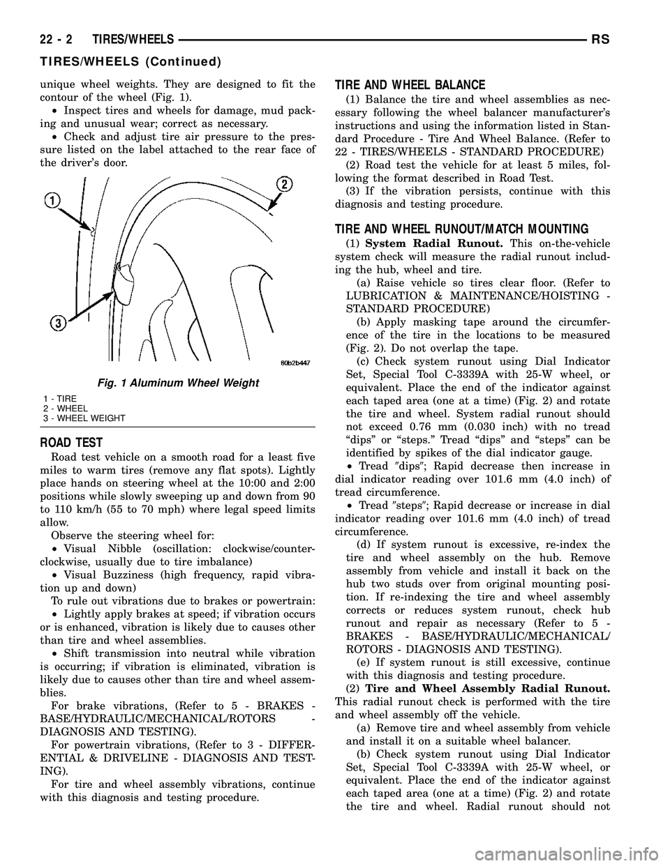
unique wheel weights. They are designed to fit the
contour of the wheel (Fig. 1).
²Inspect tires and wheels for damage, mud pack-
ing and unusual wear; correct as necessary.
²Check and adjust tire air pressure to the pres-
sure listed on the label attached to the rear face of
the driver's door.
ROAD TEST
Road test vehicle on a smooth road for a least five
miles to warm tires (remove any flat spots). Lightly
place hands on steering wheel at the 10:00 and 2:00
positions while slowly sweeping up and down from 90
to 110 km/h (55 to 70 mph) where legal speed limits
allow.
Observe the steering wheel for:
²Visual Nibble (oscillation: clockwise/counter-
clockwise, usually due to tire imbalance)
²Visual Buzziness (high frequency, rapid vibra-
tion up and down)
To rule out vibrations due to brakes or powertrain:
²Lightly apply brakes at speed; if vibration occurs
or is enhanced, vibration is likely due to causes other
than tire and wheel assemblies.
²Shift transmission into neutral while vibration
is occurring; if vibration is eliminated, vibration is
likely due to causes other than tire and wheel assem-
blies.
For brake vibrations, (Refer to 5 - BRAKES -
BASE/HYDRAULIC/MECHANICAL/ROTORS -
DIAGNOSIS AND TESTING).
For powertrain vibrations, (Refer to 3 - DIFFER-
ENTIAL & DRIVELINE - DIAGNOSIS AND TEST-
ING).
For tire and wheel assembly vibrations, continue
with this diagnosis and testing procedure.
TIRE AND WHEEL BALANCE
(1) Balance the tire and wheel assemblies as nec-
essary following the wheel balancer manufacturer's
instructions and using the information listed in Stan-
dard Procedure - Tire And Wheel Balance. (Refer to
22 - TIRES/WHEELS - STANDARD PROCEDURE)
(2) Road test the vehicle for at least 5 miles, fol-
lowing the format described in Road Test.
(3) If the vibration persists, continue with this
diagnosis and testing procedure.
TIRE AND WHEEL RUNOUT/MATCH MOUNTING
(1)System Radial Runout.This on-the-vehicle
system check will measure the radial runout includ-
ing the hub, wheel and tire.
(a) Raise vehicle so tires clear floor. (Refer to
LUBRICATION & MAINTENANCE/HOISTING -
STANDARD PROCEDURE)
(b) Apply masking tape around the circumfer-
ence of the tire in the locations to be measured
(Fig. 2). Do not overlap the tape.
(c) Check system runout using Dial Indicator
Set, Special Tool C-3339A with 25-W wheel, or
equivalent. Place the end of the indicator against
each taped area (one at a time) (Fig. 2) and rotate
the tire and wheel. System radial runout should
not exceed 0.76 mm (0.030 inch) with no tread
ªdipsº or ªsteps.º Tread ªdipsº and ªstepsº can be
identified by spikes of the dial indicator gauge.
²Tread9dips9; Rapid decrease then increase in
dial indicator reading over 101.6 mm (4.0 inch) of
tread circumference.
²Tread9steps9; Rapid decrease or increase in dial
indicator reading over 101.6 mm (4.0 inch) of tread
circumference.
(d) If system runout is excessive, re-index the
tire and wheel assembly on the hub. Remove
assembly from vehicle and install it back on the
hub two studs over from original mounting posi-
tion. If re-indexing the tire and wheel assembly
corrects or reduces system runout, check hub
runout and repair as necessary (Refer to 5 -
BRAKES - BASE/HYDRAULIC/MECHANICAL/
ROTORS - DIAGNOSIS AND TESTING).
(e) If system runout is still excessive, continue
with this diagnosis and testing procedure.
(2)Tire and Wheel Assembly Radial Runout.
This radial runout check is performed with the tire
and wheel assembly off the vehicle.
(a) Remove tire and wheel assembly from vehicle
and install it on a suitable wheel balancer.
(b) Check system runout using Dial Indicator
Set, Special Tool C-3339A with 25-W wheel, or
equivalent. Place the end of the indicator against
each taped area (one at a time) (Fig. 2) and rotate
the tire and wheel. Radial runout should not
Fig. 1 Aluminum Wheel Weight
1 - TIRE
2 - WHEEL
3 - WHEEL WEIGHT
22 - 2 TIRES/WHEELSRS
TIRES/WHEELS (Continued)
Page 2092 of 2585
TIRES
DESCRIPTION
DESCRIPTION - TIRE
Tires are designed and engineered for each specific
vehicle. They provide the best overall performance
for normal operation. The ride and handling charac-
teristics match the vehicle's requirements. With
proper care they will give excellent reliability, trac-
tion, skid resistance, and tread life.
Driving habits have more effect on tire life than
any other factor. Careful drivers will obtain, in most
cases, much greater mileage than severe use or care-
less drivers. A few of the driving habits which will
shorten the life of any tire are:
²Rapid acceleration
²Severe application of brakes
²High-speed driving
²Taking turns at excessive speeds
²Striking curbs and other obstacles
²Operating vehicle with over or under inflated
tire pressures
Radial ply tires are more prone to irregular tread
wear. It is important to follow the tire rotation inter-
val shown in the section on Tire Rotation. This will
help to achieve a greater tread-life potential.
TIRE IDENTIFICATION
Tire type, size, load index and speed rating are
encoded in the letters and numbers imprinted on the
side wall of the tire. Refer to the Tire Identification
chart to decipher the code. For example purposes, the
tire size P225/60 R 16 97 T is used in the chart. An
All Season type tire will also have eitherM+S,M&
SorM-S(indicating mud and snow traction)
imprinted on the side wall. An Extra or Light Load
marking ªXLº or ªLLº may also be listed on the side-
wall. The absence of an ªXLº or ªLLº marking infers
a standard load tire.
TIRE IDENTIFICATION
PTIRE TYPE (Not
present on all tires)P - Passenger
T - Temporary
C - Commercial
LT - Light Truck
225SECTIONAL WIDTHSHOWN IN
MILLIMETERS
60ASPECT RATIOSECTIONAL HEIGHT
÷ SECTIONAL WIDTH
(Refer to Aspect Ratio
Figure 22 )
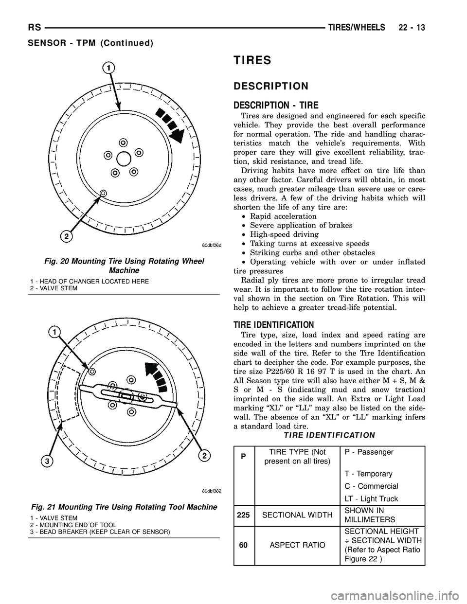
Fig. 20 Mounting Tire Using Rotating Wheel
Machine
1 - HEAD OF CHANGER LOCATED HERE
2 - VALVE STEM
Fig. 21 Mounting Tire Using Rotating Tool Machine
1 - VALVE STEM
2 - MOUNTING END OF TOOL
3 - BEAD BREAKER (KEEP CLEAR OF SENSOR)
RSTIRES/WHEELS22-13
SENSOR - TPM (Continued)
Page 2099 of 2585
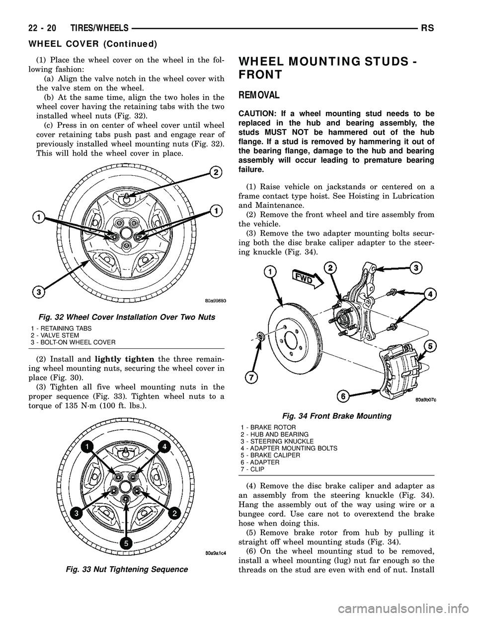
(1) Place the wheel cover on the wheel in the fol-
lowing fashion:
(a) Align the valve notch in the wheel cover with
the valve stem on the wheel.
(b) At the same time, align the two holes in the
wheel cover having the retaining tabs with the two
installed wheel nuts (Fig. 32).
(c) Press in on center of wheel cover until wheel
cover retaining tabs push past and engage rear of
previously installed wheel mounting nuts (Fig. 32).
This will hold the wheel cover in place.
(2) Install andlightly tightenthe three remain-
ing wheel mounting nuts, securing the wheel cover in
place (Fig. 30).
(3) Tighten all five wheel mounting nuts in the
proper sequence (Fig. 33). Tighten wheel nuts to a
torque of 135 N´m (100 ft. lbs.).WHEEL MOUNTING STUDS -
FRONT
REMOVAL
CAUTION: If a wheel mounting stud needs to be
replaced in the hub and bearing assembly, the
studs MUST NOT be hammered out of the hub
flange. If a stud is removed by hammering it out of
the bearing flange, damage to the hub and bearing
assembly will occur leading to premature bearing
failure.
(1) Raise vehicle on jackstands or centered on a
frame contact type hoist. See Hoisting in Lubrication
and Maintenance.
(2) Remove the front wheel and tire assembly from
the vehicle.
(3) Remove the two adapter mounting bolts secur-
ing both the disc brake caliper adapter to the steer-
ing knuckle (Fig. 34).
(4) Remove the disc brake caliper and adapter as
an assembly from the steering knuckle (Fig. 34).
Hang the assembly out of the way using wire or a
bungee cord. Use care not to overextend the brake
hose when doing this.
(5) Remove brake rotor from hub by pulling it
straight off wheel mounting studs (Fig. 34).
(6) On the wheel mounting stud to be removed,
install a wheel mounting (lug) nut far enough so the
threads on the stud are even with end of nut. Install
Fig. 32 Wheel Cover Installation Over Two Nuts
1 - RETAINING TABS
2 - VALVE STEM
3 - BOLT-ON WHEEL COVER
Fig. 33 Nut Tightening Sequence
Fig. 34 Front Brake Mounting
1 - BRAKE ROTOR
2 - HUB AND BEARING
3 - STEERING KNUCKLE
4 - ADAPTER MOUNTING BOLTS
5 - BRAKE CALIPER
6 - ADAPTER
7 - CLIP
22 - 20 TIRES/WHEELSRS
WHEEL COVER (Continued)
Page 2106 of 2585
TIRES
TABLE OF CONTENTS
page page
TIRES DESCRIPTION DESCRIPTION - TIRE ...................5
DESCRIPTION - RADIAL-PLY TIRES ........6
DESCRIPTION - REPLACEMENT TIRES .....6
DESCRIPTION - SPARE TIRE (TEMPORARY) ........................6
DIAGNOSIS AND TESTING DIAGNOSIS AND TESTING - TIRE NOISE ....6
DIAGNOSIS AND TESTING - TIRE/VEHICLE LEAD ................................6
DIAGNOSIS AND TESTING - TIRE WEAR PATTERNS ...........................8 DIAGNOSIS AND TESTING - TREAD WEAR
INDICATORS ..........................8
STANDARD PROCEDURE STANDARD PROCEDURE - TIRE INFLATIONPRESSURES ..........................8
STANDARD PROCEDURE - TIRE PRESSURE FOR HIGH SPEED
OPERATION ..........................9
STANDARD PROCEDURE - TIRE LEAK REPAIRING ...........................9
CLEANING - TIRES .....................10
TIRES
DESCRIPTION
DESCRIPTION - TIRE
Tires are designed and engineered for each specific
vehicle. They provide the best overall performance
for normal operation. The ride and handling charac-
teristics match the vehicle's requirements. With
proper care they will give excellent reliability, trac-
tion, skid resistance, and tread life. Driving habits have more effect on tire life than
any other factor. Careful drivers will obtain, in most
cases, much greater mileage than severe use or care-
less drivers. A few of the driving habits which will
shorten the life of any tire are: ² Rapid acceleration
² Severe application of brakes
² High-speed driving
² Taking turns at excessive speeds
² Striking curbs and other obstacles
² Operating vehicle with over or under inflated
tire pressures Radial ply tires are more prone to irregular tread
wear. It is important to follow the tire rotation inter-
val shown in the section on Tire Rotation. This will
help to achieve a greater tread-life potential.
TIRE IDENTIFICATION
Tire type, size, load index and speed rating are
encoded in the letters and numbers imprinted on the
side wall of the tire. Refer to the Tire Identification
chart to decipher the code. For example purposes, the tire size P225/60 R 16 97 T is used in the chart. An
All Season type tire will also have eithe
rM+S,M&
SorM-S (indicating mud and snow traction)
imprinted on the side wall. An Extra or Light Load
marking ªXLº or ªLLº may also be listed on the side-
wall. The absence of an ªXLº or ªLLº marking infers
a standard load tire.
TIRE IDENTIFICATION
P TIRE TYPE (Not
present on all tires) P - Passenger
T - Temporary
C - Commercial
LT - Light Truck
225 SECTIONAL WIDTH SHOWN IN
MILLIMETERS
60 ASPECT RATIO SECTIONAL HEIGHT
÷ SECTIONAL WIDTH
(Refer to Aspect Ratio
Figure 1 )
R CONSTRUCTION
TYPE R - RADIAL
B - BIAS BELTED
D - DIAGONAL (BIAS)
16 WHEEL DIAMETER SHOWN IN INCHES
97 LOAD INDEX *
T SPEED RATING *
* NOTE: Consult the tire manufacturer regarding
any questions on tire specifications or capabilities.
RS TIRES22s-5
Page 2479 of 2585
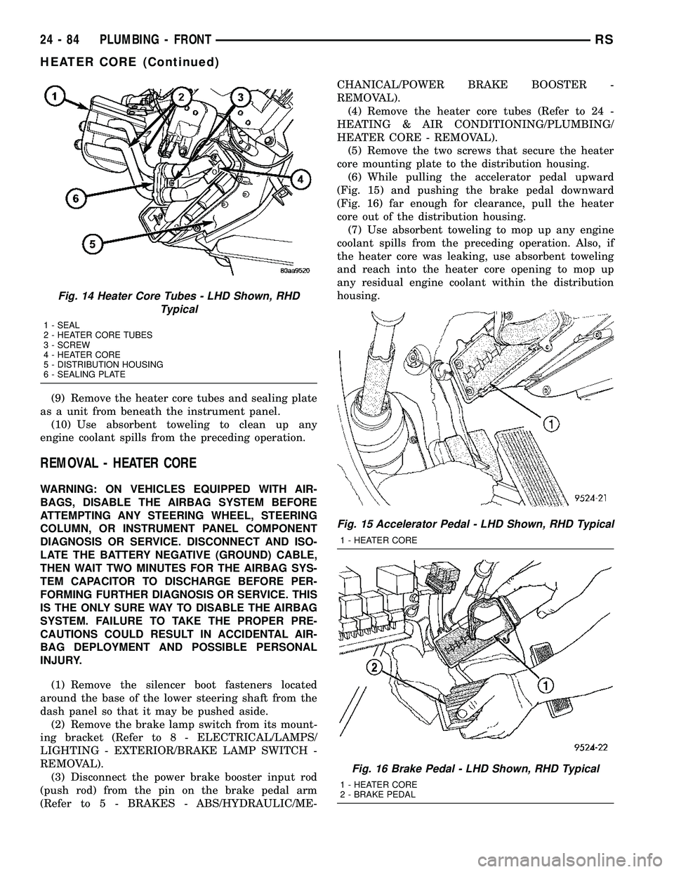
(9) Remove the heater core tubes and sealing plate
as a unit from beneath the instrument panel.
(10) Use absorbent toweling to clean up any
engine coolant spills from the preceding operation.
REMOVAL - HEATER CORE
WARNING: ON VEHICLES EQUIPPED WITH AIR-
BAGS, DISABLE THE AIRBAG SYSTEM BEFORE
ATTEMPTING ANY STEERING WHEEL, STEERING
COLUMN, OR INSTRUMENT PANEL COMPONENT
DIAGNOSIS OR SERVICE. DISCONNECT AND ISO-
LATE THE BATTERY NEGATIVE (GROUND) CABLE,
THEN WAIT TWO MINUTES FOR THE AIRBAG SYS-
TEM CAPACITOR TO DISCHARGE BEFORE PER-
FORMING FURTHER DIAGNOSIS OR SERVICE. THIS
IS THE ONLY SURE WAY TO DISABLE THE AIRBAG
SYSTEM. FAILURE TO TAKE THE PROPER PRE-
CAUTIONS COULD RESULT IN ACCIDENTAL AIR-
BAG DEPLOYMENT AND POSSIBLE PERSONAL
INJURY.
(1) Remove the silencer boot fasteners located
around the base of the lower steering shaft from the
dash panel so that it may be pushed aside.
(2) Remove the brake lamp switch from its mount-
ing bracket (Refer to 8 - ELECTRICAL/LAMPS/
LIGHTING - EXTERIOR/BRAKE LAMP SWITCH -
REMOVAL).
(3) Disconnect the power brake booster input rod
(push rod) from the pin on the brake pedal arm
(Refer to 5 - BRAKES - ABS/HYDRAULIC/ME-CHANICAL/POWER BRAKE BOOSTER -
REMOVAL).
(4) Remove the heater core tubes (Refer to 24 -
HEATING & AIR CONDITIONING/PLUMBING/
HEATER CORE - REMOVAL).
(5) Remove the two screws that secure the heater
core mounting plate to the distribution housing.
(6) While pulling the accelerator pedal upward
(Fig. 15) and pushing the brake pedal downward
(Fig. 16) far enough for clearance, pull the heater
core out of the distribution housing.
(7) Use absorbent toweling to mop up any engine
coolant spills from the preceding operation. Also, if
the heater core was leaking, use absorbent toweling
and reach into the heater core opening to mop up
any residual engine coolant within the distribution
housing.
Fig. 14 Heater Core Tubes - LHD Shown, RHD
Typical
1 - SEAL
2 - HEATER CORE TUBES
3 - SCREW
4 - HEATER CORE
5 - DISTRIBUTION HOUSING
6 - SEALING PLATE
Fig. 15 Accelerator Pedal - LHD Shown, RHD Typical
1 - HEATER CORE
Fig. 16 Brake Pedal - LHD Shown, RHD Typical
1 - HEATER CORE
2 - BRAKE PEDAL
24 - 84 PLUMBING - FRONTRS
HEATER CORE (Continued)
Page 2480 of 2585
INSTALLATION
INSTALLATION - HEATER CORE TUBES
(1) Remove the plugs or tape from both heater core
tube fittings and both heater core ports.
(2) Position the heater core tubes and sealing plate
as a unit beneath the instrument panel.
(3) Align the engine compartment ends of both
heater core tubes with the openings in the dash
panel seal and push them simultaneously forward
through the seal far enough to engage the heater
core ends of the tubes with the heater core supply
and return ports.
(4) Position both heater core tubes and the sealing
plate simultaneously to the heater core supply and
return ports.
NOTE: The heater core tubes each have a slot that
must be indexed to a location tab within each of the
heater core ports. Adjust the position of the tubes
as required so that the sealing plate fits flush
against the heater core supply and return ports,
which indicates that the tubes are properly indexed.
(5) Index both heater core tubes to the heater core
ports.
(6) Install the screw that secures the heater core
tube sealing plate to the heater core supply and
return ports. Tighten the screw to 3 N´m (27 in. lbs.).
(7) Install the silencer under the driver side end of
the instrument panel.
(8) Connect the heater hoses to the heater hose
tubes (Refer to 24 - HEATING & AIR CONDITION-
ING/PLUMBING/HEATER INLET HOSE - INSTAL-
LATION) and(Refer to 24 - HEATING & AIR
CONDITIONING/PLUMBING/HEATER RETURN
HOSE - INSTALLATION).
(9) Reconnect the battery negative cable.
(10) Refill the engine cooling system (Refer to 7 -
COOLING - STANDARD PROCEDURE - COOLING
SYSTEM REFILL).
INSTALLATION - HEATER CORE
(1) While pushing the brake pedal downward and
pulling the accelerator pedal upward far enough for
clearance, slide the heater core into the distribution
housing.
(2) Install the two screws that secure the heater
core mounting plate to the distribution housing.
Tighten the screws to 2 N´m (17 in. lbs.).
(3) Install the heater core tubes (Refer to 24 -
HEATING & AIR CONDITIONING/PLUMBING/
HEATER CORE - INSTALLATION).
(4) Reconnect the power brake booster input rod
(push rod) to the pin on the brake pedal arm (Referto 5 - BRAKES/HYDRAULIC/MECHANICAL/
POWER BRAKE BOOSTER - INSTALLATION).
(5) Reinstall the brake lamp switch into its mount-
ing bracket (Refer to 8 - ELECTRICAL/LAMPS/
LIGHTING - EXTERIOR/BRAKE LAMP SWITCH -
INSTALLATION).
(6) Reinstall the silencer boot around the base of
the lower steering shaft on the dash panel.
(7) Reconnect the battery negative cable.
(8) Refill the engine cooling system (Refer to 7 -
COOLING - STANDARD PROCEDURE - COOLING
SYSTEM REFILL).
(9) Operate system for two thermostat cycles to
assure the elimination of any air that may be
trapped within the cooling system.
HEATER INLET HOSE
REMOVAL
WARNING: REFER TO THE APPLICABLE WARN-
INGS AND CAUTIONS FOR THIS SYSTEM BEFORE
PERFORMING THE FOLLOWING OPERATION (Refer
to 24 - HEATING & AIR CONDITIONING/PLUMBING -
WARNING).
NOTE: The heater inlet hose is constructed from
formed steel tubing and rubber hoses. Depending
on application, the ends are secured to the heater
core, engine oil cooler or the engine by spring ten-
sion clamps.
(1) Drain the engine cooling system (Refer to 7 -
COOLING - STANDARD PROCEDURE - COOLING
SYSTEM DRAIN).
(2) Using spring tension clamp pliers, compress
and slide the clamps off of each end of the hose being
removed (Fig. 17), (Fig. 18) or (Fig. 19).
CAUTION:
DO NOT apply excessive pressure on heater tubes
or connections when removing heater hoses.
Excessive pressure may damage or deform the
tubes/heater core, causing an engine coolant leak.
(3) Disconnect each hose end by carefully twisting
the hose back and forth on the tube or nipple, while
gently pulling it away from the end of the tube or
nipple.
NOTE:
Replacement of the heater inlet hoses will be
required if the hose ends are cut for removal.
(4) If necessary, carefully cut the hose end and
peel the hose off of the tube or nipple.
RSPLUMBING - FRONT24-85
HEATER CORE (Continued)
Page 2532 of 2585
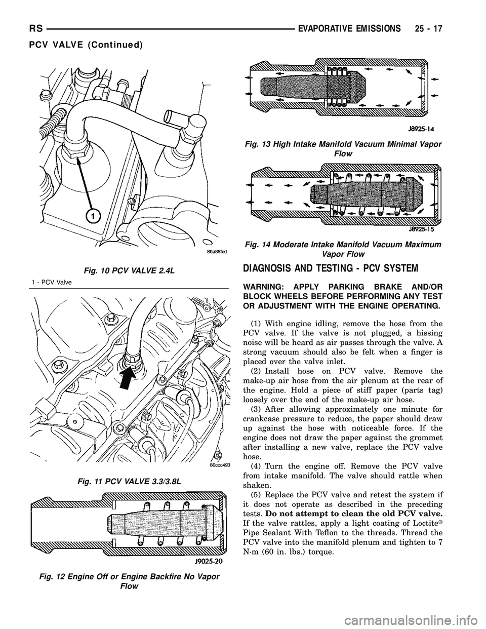
DIAGNOSIS AND TESTING - PCV SYSTEM
WARNING: APPLY PARKING BRAKE AND/OR
BLOCK WHEELS BEFORE PERFORMING ANY TEST
OR ADJUSTMENT WITH THE ENGINE OPERATING.
(1) With engine idling, remove the hose from the
PCV valve. If the valve is not plugged, a hissing
noise will be heard as air passes through the valve. A
strong vacuum should also be felt when a finger is
placed over the valve inlet.
(2) Install hose on PCV valve. Remove the
make-up air hose from the air plenum at the rear of
the engine. Hold a piece of stiff paper (parts tag)
loosely over the end of the make-up air hose.
(3) After allowing approximately one minute for
crankcase pressure to reduce, the paper should draw
up against the hose with noticeable force. If the
engine does not draw the paper against the grommet
after installing a new valve, replace the PCV valve
hose.
(4) Turn the engine off. Remove the PCV valve
from intake manifold. The valve should rattle when
shaken.
(5) Replace the PCV valve and retest the system if
it does not operate as described in the preceding
tests.Do not attempt to clean the old PCV valve.
If the valve rattles, apply a light coating of Loctitet
Pipe Sealant With Teflon to the threads. Thread the
PCV valve into the manifold plenum and tighten to 7
N´m (60 in. lbs.) torque.
Fig. 10 PCV VALVE 2.4L
1 - PCV Valve
Fig. 11 PCV VALVE 3.3/3.8L
Fig. 12 Engine Off or Engine Backfire No Vapor
Flow
Fig. 13 High Intake Manifold Vacuum Minimal Vapor
Flow
Fig. 14 Moderate Intake Manifold Vacuum Maximum
Vapor Flow
RSEVAPORATIVE EMISSIONS25-17
PCV VALVE (Continued)
Page 2556 of 2585
ENGINE OIL LEVEL CHECK, STANDARD
PROCEDURE.........................9-53
ENGINE OIL PRESSURE - DIAGNOSIS
AND TESTING.......................9-136
ENGINE OIL PRESSURE - DIAGNOSIS
AND TESTING, CHECKING...............9-52
ENGINE, SPECIAL TOOLS - 2.4L..........9-21
ENGINE, SPECIAL TOOLS - 3.3/3.8L.......9-95
ENGINE, SPECIFICATIONS - 3.3/3.8L . . 9-91,9s-11
ENGINE SPEED SENSOR - DESCRIPTION . . 14-26
ENGINE SPEED SENSOR - OPERATION....14-26
ENGINES - DESCRIPTION, ENGINE OIL -
DIESEL..............................0-6
ENGINES - DIAGNOSIS AND TESTING,
SYSTEM CHARGE LEVEL TEST -
GASOLINE..........................24-67
ENGINES - EXPORT - DESCRIPTION,
DIESEL.............................0-24
ENTRY MODULE - DESCRIPTION,
REMOTE KEYLESS...................8N-43
ENTRY MODULE - DESCRIPTION,
SENTRY KEY REMOTE.................8Q-3
ENTRY MODULE - DIAGNOSIS AND
TESTING, REMOTE KEYLESS...........8N-43
ENTRY MODULE - DIAGNOSIS AND
TESTING, SENTRY KEY REMOTE.........8Q-5
ENTRY MODULE - INSTALLATION,
REMOTE KEYLESS...................8N-44
ENTRY MODULE - INSTALLATION,
SENTRY KEY REMOTE.................8Q-6
ENTRY MODULE - OPERATION, REMOTE
KEYLESS...........................8N-43
ENTRY MODULE - OPERATION, SENTRY
KEY REMOTE........................8Q-4
ENTRY MODULE - REMOVAL, REMOTE
KEYLESS...........................8N-44
ENTRY MODULE - REMOVAL, SENTRY
KEY REMOTE........................8Q-5
ENTRY SYSTEM - DIAGNOSIS AND
TESTING, SENTRY KEY REMOTE.........8Q-3
ENTRY TRANSMITTER - DIAGNOSIS AND
TESTING, KEYLESS..............8N-42,8N-5
ENTRY TRANSMITTER PROGRAMMING -
STANDARD PROCEDURE, REMOTE
KEYLESS............................8N-5
EQUIPMENT - STANDARD PROCEDURE,
REFRIGERANT SYSTEM SERVICE........24-70
ERASING TRANSMITTER CODES -
STANDARD PROCEDURE..............8M-11
EVACUATE - STANDARD PROCEDURE,
REFRIGERANT SYSTEM...............24-72
EVAP CANISTER - INSTALLATION, REAR . . 25-20
EVAP CANISTER - REMOVAL, REAR......25-19
EVAPORATION CONTROL SYSTEM -
OPERATION.........................25-10
EVAPORATOR - DESCRIPTION, A/C . 24-80,24-97
EVAPORATOR - INSTALLATION, A/C......24-80
EVAPORATOR - INSTALLATION, REAR
A/C................................24-99
EVAPORATOR - OPERATION, A/C . . . 24-80,24-97
EVAPORATOR - REMOVAL, A/C..........24-80
EVAPORATOR - REMOVAL, REAR A/C.....24-97
EVAPORATOR LINE EXTENSION -
INSTALLATION, REAR A/C..............24-99
EVAPORATOR LINE EXTENSION -
REMOVAL, A/C......................24-98
EVAPORATOR TEMPERATURE SENSOR -
DESCRIPTION.......................24-27
EVAPORATOR TEMPERATURE SENSOR -
OPERATION.........................24-28
EVAP/PURGE SOLENOID - DESCRIPTION . . 25-12
EVAP/PURGE SOLENOID - INSTALLATION . 25-12
EVAP/PURGE SOLENOID - OPERATION....25-12
EVAP/PURGE SOLENOID - REMOVAL.....25-12
EXCESSIVE EXHAUST SYSTEM NOISE -
DIAGNOSIS AND TESTING..............11-2
EXHAUST MANIFOLD - CLEANING........9-61
EXHAUST MANIFOLD - INSPECTION.......9-61
EXHAUST MANIFOLD - INSTALLATION.....9-61
EXHAUST MANIFOLD - LEFT - CLEANING . . 9-152
EXHAUST MANIFOLD - LEFT -
INSPECTION
........................9-152
EXHAUST MANIFOLD - LEFT -
INSTALLATION
.......................9-152
EXHAUST MANIFOLD - LEFT - REMOVAL
. . 9-152
EXHAUST MANIFOLD - REMOVAL
.........9-61
EXHAUST MANIFOLD - RIGHT -
CLEANING
..........................9-151EXHAUST MANIFOLD - RIGHT -
INSPECTION........................9-151
EXHAUST MANIFOLD - RIGHT -
INSTALLATION.......................9-151
EXHAUST MANIFOLD - RIGHT -
REMOVAL..........................9-150
EXHAUST SYSTEM - DESCRIPTION.......11-1
EXHAUST SYSTEM NOISE - DIAGNOSIS
AND TESTING, EXCESSIVE..............11-2
EXHAUST SYSTEM RESTRICTION CHECK
- DIAGNOSIS AND TESTING.............11-2
EXHAUST SYSTEM, SPECIAL TOOLS......11-4
EXHAUST TUBE - INSTALLATION.......24-115
EXHAUST TUBE - REMOVAL...........24-114
EXHAUSTER - DESCRIPTION, REAR
QUARTER PANEL/FENDER AIR..........23-57
EXHAUSTER - INSTALLATION, REAR
QUARTER PANEL/FENDER AIR..........23-58
EXHAUSTER - REMOVAL, REAR
QUARTER PANEL/FENDER AIR..........23-57
EXPANSION VALVE - DESCRIPTION......24-81
EXPANSION VALVE - DESCRIPTION, A/C . . 24-99
EXPANSION VALVE - DIAGNOSIS AND
TESTING..........................24-100
EXPANSION VALVE - DIAGNOSIS AND
TESTING, A/C.......................24-81
EXPANSION VALVE - INSTALLATION......24-82
EXPANSION VALVE - INSTALLATION, A/C . 24-100
EXPANSION VALVE - OPERATION........24-81
EXPANSION VALVE - OPERATION, A/C....24-99
EXPANSION VALVE - REMOVAL.........24-82
EXPANSION VALVE - REMOVAL, A/C.....24-100
EXPORT - BRAKE ROTOR..........5-55,5s-58
EXPORT - DESCRIPTION...........5-58,5s-60
EXPORT - DESCRIPTION................0-15
EXPORT - DESCRIPTION................2-10
EXPORT - DESCRIPTION, ANTENNA
MODULE............................8A-6
EXPORT - DESCRIPTION, DIESEL
ENGINES............................0-24
EXPORT - DESCRIPTION, DOOR
CYLINDER LOCK SWITCH...............8N-3
EXPORT - DESCRIPTION, POWER
FOLDAWAY MIRROR SWITCH..........8N-48
EXPORT - DESCRIPTION, QUARTER
GLASS INTEGRAL ANTENNA.............8A-9
EXPORT - DIAGNOSIS AND TESTING,
ANTENNA MODULE....................8A-7
EXPORT - DIAGNOSIS AND TESTING,
DOOR CYLINDER LOCK SWITCH.........8N-3
EXPORT - DIAGNOSIS AND TESTING,
QUARTER GLASS INTEGRAL ANTENNA....8A-9
EXPORT - INSTALLATION...............2-11
EXPORT - INSTALLATION, ANTENNA
MODULE............................8A-7
EXPORT - INSTALLATION, DOOR
CYLINDER LOCK SWITCH...............8N-4
EXPORT - INSTALLATION, HEADLAMP
UNIT..............................8L-17
EXPORT - INSTALLATION, HOOD AJAR
SWITCH............................8Q-3
EXPORT - INSTALLATION, POWER
FOLDAWAY MIRROR SWITCH..........8N-49
EXPORT - OPERATION, ANTENNA
MODULE............................8A-6
EXPORT - OPERATION, DOOR CYLINDER
LOCK SWITCH........................8N-3
EXPORT - OPERATION, POWER
FOLDAWAY MIRROR SWITCH..........8N-48
EXPORT - OPERATION, QUARTER GLASS
INTEGRAL ANTENNA...................8A-9
EXPORT - REMOVAL...................2-11
EXPORT - REMOVAL, ANTENNA MODULE . . 8A-7
EXPORT - REMOVAL, DOOR CYLINDER
LOCK SWITCH........................8N-3
EXPORT - REMOVAL, HEADLAMP UNIT . . . 8L-17
EXPORT - REMOVAL, HOOD AJAR
SWITCH............................8Q-3
EXPORT - REMOVAL, POWER
FOLDAWAY MIRROR SWITCH
..........8N-48
EXPORT - STANDARD PROCEDURE,
FRONT FOG LAMP UNIT ALIGNMENT
......8L-9
EXPORT - STANDARD PROCEDURE,
HEADLAMP UNIT ALIGNMENT
..........8L-14
EXTENSION - INSTALLATION, REAR A/C
EVAPORATOR LINE
...................24-99
EXTENSION - REMOVAL, A/C
EVAPORATOR LINE
...................24-98EXTENSION TRIM - INSTALLATION,
A-PILLAR LOWER....................23-74
EXTENSION TRIM - REMOVAL, A-PILLAR
LOWER............................23-74
EXTERIOR - DESCRIPTION, LAMPS/
LIGHTING...........................8L-2
EXTERIOR - OPERATION, LAMPS/
LIGHTING...........................8L-2
EXTERIOR - WARNING, LAMPS/
LIGHTING...........................8L-3
EXTERIOR HANDLE - INSTALLATION.....23-22,
23-40
EXTERIOR HANDLE - REMOVAL....23-21,23-40
EXTERIOR HANDLE SWITCH -
DESCRIPTION.......................8N-11
EXTERIOR HANDLE SWITCH -
INSTALLATION......................8N-12
EXTERIOR HANDLE SWITCH -
OPERATION.........................8N-11
EXTERIOR HANDLE SWITCH - REMOVAL . . 8N-11
EXTERIOR LAMPS, SPECIFICATIONS......8L-3
EXTERIOR NAME PLATES - ADHESIVE
ATTACHED - INSTALLATION............23-51
EXTERIOR NAME PLATES - ADHESIVE
ATTACHED - REMOVAL................23-51
EXTERIOR NAME PLATES - TAPE
ATTACHED - INSTALLATION............23-51
EXTERIOR NAME PLATES - TAPE
ATTACHED - REMOVAL................23-51
FACTOR SETTING - STANDARD
PROCEDURE, PINION............8E-15,8E-23
FAILED PARK SWITCH - DIAGNOSIS AND
TESTING..............................8R-2
FAN - DESCRIPTION, RADIATOR..........7-28
FAN - INSTALLATION, RADIATOR.........7-30
FAN - OPERATION, RADIATOR...........7-29
FAN - REMOVAL, RADIATOR.............7-30
FAN MOTOR - DIAGNOSIS AND
TESTING, RADIATOR...................7-29
FAN RELAY - DESCRIPTION, RADIATOR....7-30
FAN RELAY - INSTALLATION, RADIATOR . . . 7-30
FAN RELAY - OPERATION, RADIATOR......7-30
FAN RELAY - REMOVAL, RADIATOR.......7-30
FASCIA - INSTALLATION, FRONT.........13-1
FASCIA - INSTALLATION, REAR..........13-2
FASCIA - REMOVAL, FRONT.............13-1
FASCIA - REMOVAL, REAR..............13-2
FASCIA - SCUFF PAD - INSTALLATION,
REAR...............................13-4
FASCIA - SCUFF PAD - REMOVAL, REAR . . . 13-3
FASTENER IDENTIFICATION -
DESCRIPTION......................Intro.-2
FASTENER TORQUE, SPECIFICATIONS -
ABS ................................5-79
FASTENER TORQUE, SPECIFICATIONS -
BRAKE...........................5-9,5s-8
FASTENER TORQUE, SPECIFICATIONS -
FRONT SUSPENSION...................2-3
FASTENER TORQUE, SPECIFICATIONS -
POWER STEERING....................19-9
FASTENER TORQUE, SPECIFICATIONS -
REAR SUSPENSION...................2-28
FASTENER USAGE - DESCRIPTION......Intro.-5
FEED CIRCUIT RESISTANCE TEST -
DIAGNOSIS AND TESTING.........8F-32,8F-34
FEED CIRCUIT TEST - DIAGNOSIS AND
TESTING
......................8F-33,8F-35
FENDER - INSTALLATION, FRONT
........23-52
FENDER - REMOVAL, FRONT
...........23-52
FILL - DIAGNOSIS AND TESTING,
VEHICLE DOES NOT
..................25-16
FILL - STANDARD PROCEDURE, FLUID
DRAIN
.............................21-71
FILL DOOR - INSTALLATION, FUEL
.......23-52
FILL DOOR - REMOVAL, FUEL
..........23-52
FILL DOOR BLOCKER LATCH -
INSTALLATION, FUEL
.................23-53
FILL DOOR BLOCKER LATCH -
REMOVAL, FUEL
.....................23-53
FILL DOOR BLOCKER LATCH STRIKER -
INSTALLATION, FUEL
.................23-53
FILL DOOR BLOCKER LATCH STRIKER -
REMOVAL, FUEL
.....................23-53
FILL DOOR BLOCKER LOCKOUT LINK -
INSTALLATION, FUEL
.................23-54
FILL DOOR BLOCKER LOCKOUT LINK -
REMOVAL, FUEL
.....................23-53
RSINDEX13
Description Group-Page Description Group-Page Description Group-Page