2004 CHRYSLER VOYAGER mirror
[x] Cancel search: mirrorPage 1220 of 2585
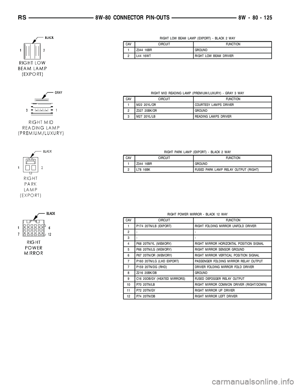
RIGHT LOW BEAM LAMP (EXPORT) - BLACK 2 WAY
CAV CIRCUIT FUNCTION
1 Z344 16BR GROUND
2 L44 16WT RIGHT LOW BEAM DRIVER
RIGHT MID READING LAMP (PREMIUM/LUXURY) - GRAY 3 WAY
CAV CIRCUIT FUNCTION
1 M22 20YL/OR COURTESY LAMPS DRIVER
2 Z327 20BK/OR GROUND
3 M27 20YL/LB READING LAMPS DRIVER
RIGHT PARK LAMP (EXPORT) - BLACK 2 WAY
CAV CIRCUIT FUNCTION
1 Z344 16BR GROUND
2 L78 16BK FUSED PARK LAMP RELAY OUTPUT (RIGHT)
RIGHT POWER MIRROR - BLACK 12 WAY
CAV CIRCUIT FUNCTION
1 P174 20TN/LB (EXPORT) RIGHT FOLDING MIRROR UNFOLD DRIVER
2- -
3- -
4 P68 20TN/YL (MEMORY) RIGHT MIRROR HORIZONTAL POSITION SIGNAL
5 P66 20TN/LG (MEMORY) RIGHT MIRROR SENSOR GROUND
6 P67 20TN/OR (MEMORY) RIGHT MIRROR VERTICAL POSITION SIGNAL
7 P160 20TN/LG (LHD EXPORT) PASSENGER FOLDING MIRROR RELAY OUTPUT
7 P159 20TN/DG (RHD) DRIVER FOLDING MIRROR FOLD DRIVER
8 Z216 20BK/DB GROUND
9 C16 20DB/GY (HEATED MIRRORS) FUSED DEFOGGER RELAY OUTPUT
10 P70 20TN/LB RIGHT MIRROR COMMON DRIVER (RIGHT/DOWN)
11 P72 20TN/GY RIGHT MIRROR UP DRIVER
12 P74 20TN/DB RIGHT MIRROR LEFT DRIVER
RS8W-80 CONNECTOR PIN-OUTS8W - 80 - 125
Page 1232 of 2585
8W-91 CONNECTOR/GROUND/SPLICE LOCATION
TABLE OF CONTENTS
page
CONNECTOR/GROUND/SPLICE LOCATION
DESCRIPTION..........................1
CONNECTOR/GROUND/SPLICE
LOCATION
DESCRIPTION
This section provides illustrations identifying con-
nector, ground, and splice locations in the vehicle.
Connector, ground, and splice indexes are provided.Use the wiring diagrams in each section for connec-
tor, ground, and splice identification. Refer to the
appropriate index for the proper figure number. For
items that are not shown in this section N/S is placed
in the Fig. column.
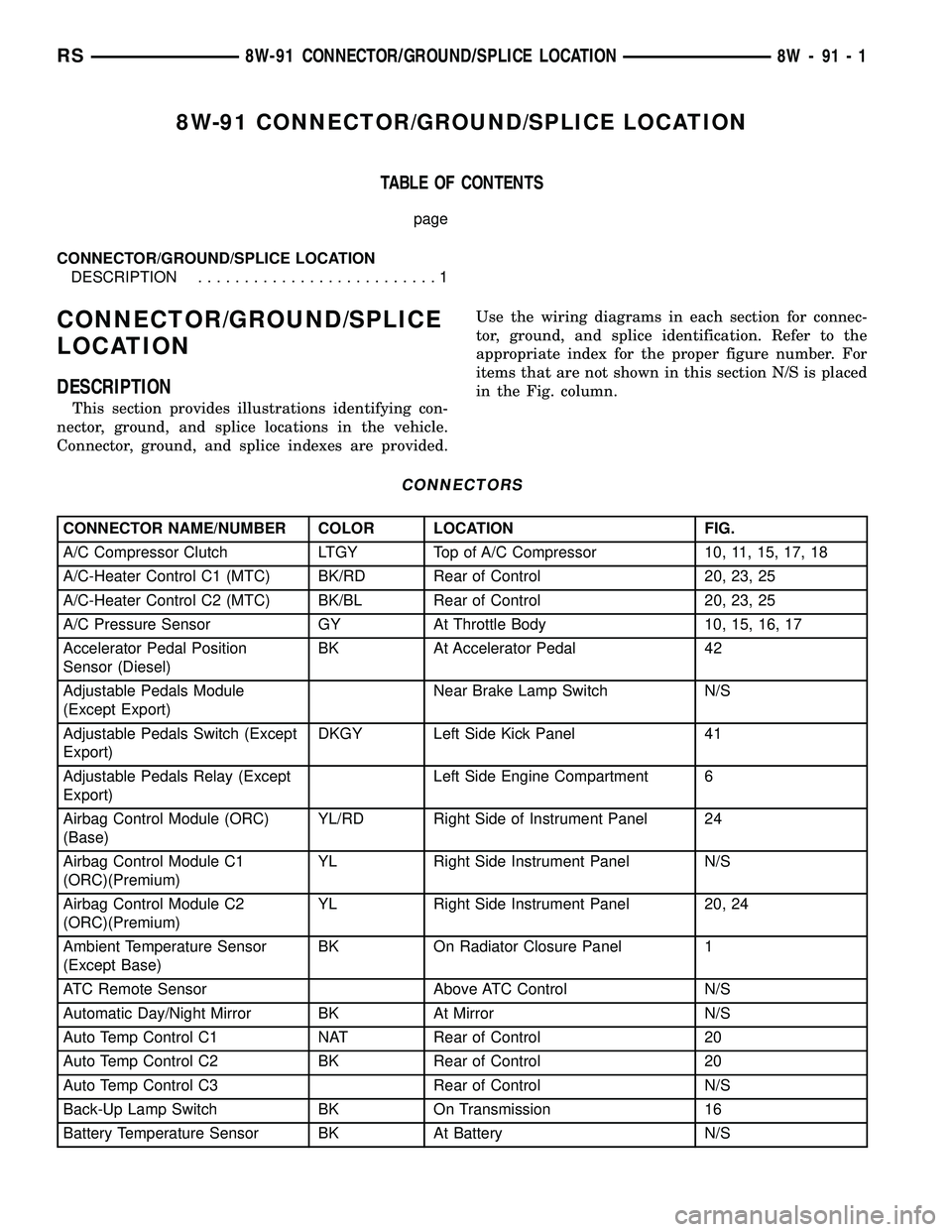
CONNECTORS
CONNECTOR NAME/NUMBER COLOR LOCATION FIG.
A/C Compressor Clutch LTGY Top of A/C Compressor 10, 11, 15, 17, 18
A/C-Heater Control C1 (MTC) BK/RD Rear of Control 20, 23, 25
A/C-Heater Control C2 (MTC) BK/BL Rear of Control 20, 23, 25
A/C Pressure Sensor GY At Throttle Body 10, 15, 16, 17
Accelerator Pedal Position
Sensor (Diesel)BK At Accelerator Pedal 42
Adjustable Pedals Module
(Except Export)Near Brake Lamp Switch N/S
Adjustable Pedals Switch (Except
Export)DKGY Left Side Kick Panel 41
Adjustable Pedals Relay (Except
Export)Left Side Engine Compartment 6
Airbag Control Module (ORC)
(Base)YL/RD Right Side of Instrument Panel 24
Airbag Control Module C1
(ORC)(Premium)YL Right Side Instrument Panel N/S
Airbag Control Module C2
(ORC)(Premium)YL Right Side Instrument Panel 20, 24
Ambient Temperature Sensor
(Except Base)BK On Radiator Closure Panel 1
ATC Remote Sensor Above ATC Control N/S
Automatic Day/Night Mirror BK At Mirror N/S
Auto Temp Control C1 NAT Rear of Control 20
Auto Temp Control C2 BK Rear of Control 20
Auto Temp Control C3 Rear of Control N/S
Back-Up Lamp Switch BK On Transmission 16
Battery Temperature Sensor BK At Battery N/S
RS8W-91 CONNECTOR/GROUND/SPLICE LOCATION8W-91-1
Page 1238 of 2585
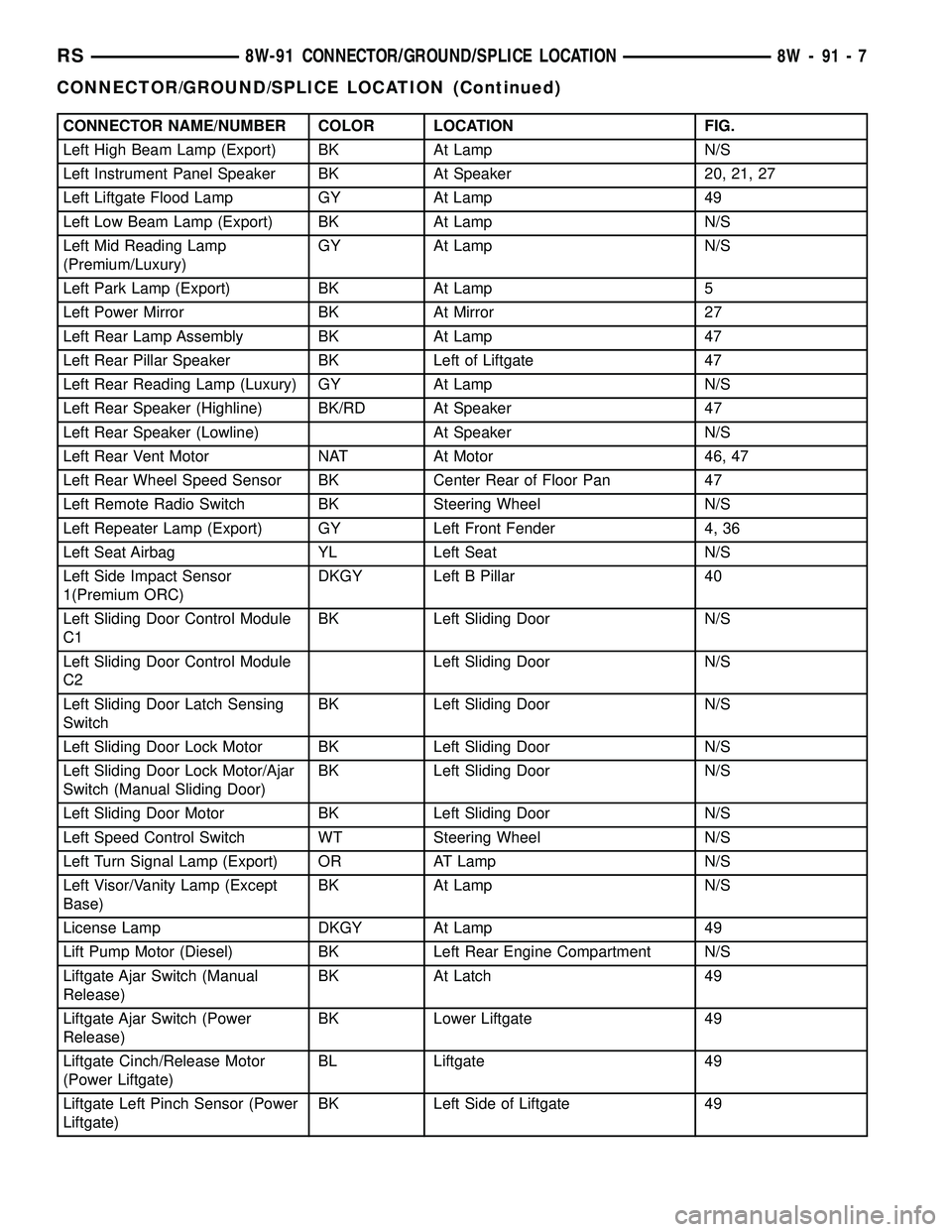
CONNECTOR NAME/NUMBER COLOR LOCATION FIG.
Left High Beam Lamp (Export) BK At Lamp N/S
Left Instrument Panel Speaker BK At Speaker 20, 21, 27
Left Liftgate Flood Lamp GY At Lamp 49
Left Low Beam Lamp (Export) BK At Lamp N/S
Left Mid Reading Lamp
(Premium/Luxury)GY At Lamp N/S
Left Park Lamp (Export) BK At Lamp 5
Left Power Mirror BK At Mirror 27
Left Rear Lamp Assembly BK At Lamp 47
Left Rear Pillar Speaker BK Left of Liftgate 47
Left Rear Reading Lamp (Luxury) GY At Lamp N/S
Left Rear Speaker (Highline) BK/RD At Speaker 47
Left Rear Speaker (Lowline) At Speaker N/S
Left Rear Vent Motor NAT At Motor 46, 47
Left Rear Wheel Speed Sensor BK Center Rear of Floor Pan 47
Left Remote Radio Switch BK Steering Wheel N/S
Left Repeater Lamp (Export) GY Left Front Fender 4, 36
Left Seat Airbag YL Left Seat N/S
Left Side Impact Sensor
1(Premium ORC)DKGY Left B Pillar 40
Left Sliding Door Control Module
C1BK Left Sliding Door N/S
Left Sliding Door Control Module
C2Left Sliding Door N/S
Left Sliding Door Latch Sensing
SwitchBK Left Sliding Door N/S
Left Sliding Door Lock Motor BK Left Sliding Door N/S
Left Sliding Door Lock Motor/Ajar
Switch (Manual Sliding Door)BK Left Sliding Door N/S
Left Sliding Door Motor BK Left Sliding Door N/S
Left Speed Control Switch WT Steering Wheel N/S
Left Turn Signal Lamp (Export) OR AT Lamp N/S
Left Visor/Vanity Lamp (Except
Base)BK At Lamp N/S
License Lamp DKGY At Lamp 49
Lift Pump Motor (Diesel) BK Left Rear Engine Compartment N/S
Liftgate Ajar Switch (Manual
Release)BK At Latch 49
Liftgate Ajar Switch (Power
Release)BK Lower Liftgate 49
Liftgate Cinch/Release Motor
(Power Liftgate)BL Liftgate 49
Liftgate Left Pinch Sensor (Power
Liftgate)BK Left Side of Liftgate 49
RS8W-91 CONNECTOR/GROUND/SPLICE LOCATION8W-91-7
CONNECTOR/GROUND/SPLICE LOCATION (Continued)
Page 1239 of 2585
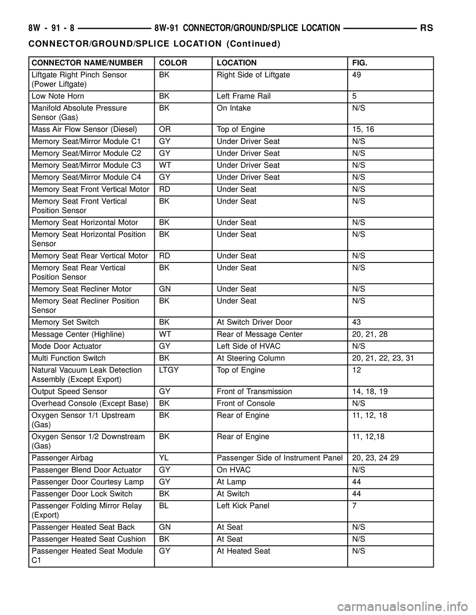
CONNECTOR NAME/NUMBER COLOR LOCATION FIG.
Liftgate Right Pinch Sensor
(Power Liftgate)BK Right Side of Liftgate 49
Low Note Horn BK Left Frame Rail 5
Manifold Absolute Pressure
Sensor (Gas)BK On Intake N/S
Mass Air Flow Sensor (Diesel) OR Top of Engine 15, 16
Memory Seat/Mirror Module C1 GY Under Driver Seat N/S
Memory Seat/Mirror Module C2 GY Under Driver Seat N/S
Memory Seat/Mirror Module C3 WT Under Driver Seat N/S
Memory Seat/Mirror Module C4 GY Under Driver Seat N/S
Memory Seat Front Vertical Motor RD Under Seat N/S
Memory Seat Front Vertical
Position SensorBK Under Seat N/S
Memory Seat Horizontal Motor BK Under Seat N/S
Memory Seat Horizontal Position
SensorBK Under Seat N/S
Memory Seat Rear Vertical Motor RD Under Seat N/S
Memory Seat Rear Vertical
Position SensorBK Under Seat N/S
Memory Seat Recliner Motor GN Under Seat N/S
Memory Seat Recliner Position
SensorBK Under Seat N/S
Memory Set Switch BK At Switch Driver Door 43
Message Center (Highline) WT Rear of Message Center 20, 21, 28
Mode Door Actuator GY Left Side of HVAC N/S
Multi Function Switch BK At Steering Column 20, 21, 22, 23, 31
Natural Vacuum Leak Detection
Assembly (Except Export)LTGY Top of Engine 12
Output Speed Sensor GY Front of Transmission 14, 18, 19
Overhead Console (Except Base) BK Front of Console N/S
Oxygen Sensor 1/1 Upstream
(Gas)BK Rear of Engine 11, 12, 18
Oxygen Sensor 1/2 Downstream
(Gas)BK Rear of Engine 11, 12,18
Passenger Airbag YL Passenger Side of Instrument Panel 20, 23, 24 29
Passenger Blend Door Actuator GY On HVAC N/S
Passenger Door Courtesy Lamp GY At Lamp 44
Passenger Door Lock Switch BK At Switch 44
Passenger Folding Mirror Relay
(Export)BL Left Kick Panel 7
Passenger Heated Seat Back GN At Seat N/S
Passenger Heated Seat Cushion BK At Seat N/S
Passenger Heated Seat Module
C1GY At Heated Seat N/S
8W - 91 - 8 8W-91 CONNECTOR/GROUND/SPLICE LOCATIONRS
CONNECTOR/GROUND/SPLICE LOCATION (Continued)
Page 1240 of 2585
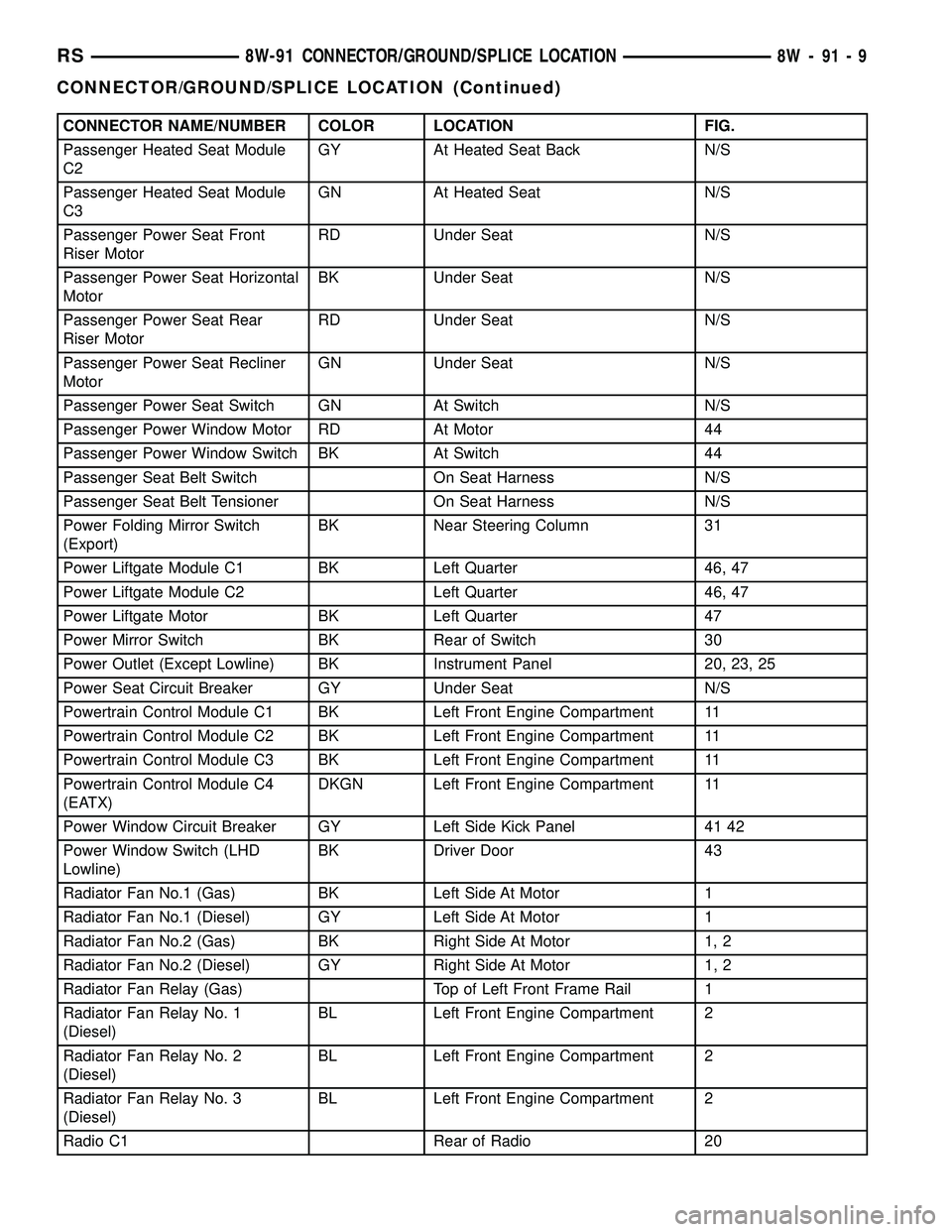
CONNECTOR NAME/NUMBER COLOR LOCATION FIG.
Passenger Heated Seat Module
C2GY At Heated Seat Back N/S
Passenger Heated Seat Module
C3GN At Heated Seat N/S
Passenger Power Seat Front
Riser MotorRD Under Seat N/S
Passenger Power Seat Horizontal
MotorBK Under Seat N/S
Passenger Power Seat Rear
Riser MotorRD Under Seat N/S
Passenger Power Seat Recliner
MotorGN Under Seat N/S
Passenger Power Seat Switch GN At Switch N/S
Passenger Power Window Motor RD At Motor 44
Passenger Power Window Switch BK At Switch 44
Passenger Seat Belt Switch On Seat Harness N/S
Passenger Seat Belt Tensioner On Seat Harness N/S
Power Folding Mirror Switch
(Export)BK Near Steering Column 31
Power Liftgate Module C1 BK Left Quarter 46, 47
Power Liftgate Module C2 Left Quarter 46, 47
Power Liftgate Motor BK Left Quarter 47
Power Mirror Switch BK Rear of Switch 30
Power Outlet (Except Lowline) BK Instrument Panel 20, 23, 25
Power Seat Circuit Breaker GY Under Seat N/S
Powertrain Control Module C1 BK Left Front Engine Compartment 11
Powertrain Control Module C2 BK Left Front Engine Compartment 11
Powertrain Control Module C3 BK Left Front Engine Compartment 11
Powertrain Control Module C4
(EATX)DKGN Left Front Engine Compartment 11
Power Window Circuit Breaker GY Left Side Kick Panel 41 42
Power Window Switch (LHD
Lowline)BK Driver Door 43
Radiator Fan No.1 (Gas) BK Left Side At Motor 1
Radiator Fan No.1 (Diesel) GY Left Side At Motor 1
Radiator Fan No.2 (Gas) BK Right Side At Motor 1, 2
Radiator Fan No.2 (Diesel) GY Right Side At Motor 1, 2
Radiator Fan Relay (Gas) Top of Left Front Frame Rail 1
Radiator Fan Relay No. 1
(Diesel)BL Left Front Engine Compartment 2
Radiator Fan Relay No. 2
(Diesel)BL Left Front Engine Compartment 2
Radiator Fan Relay No. 3
(Diesel)BL Left Front Engine Compartment 2
Radio C1 Rear of Radio 20
RS8W-91 CONNECTOR/GROUND/SPLICE LOCATION8W-91-9
CONNECTOR/GROUND/SPLICE LOCATION (Continued)
Page 1242 of 2585
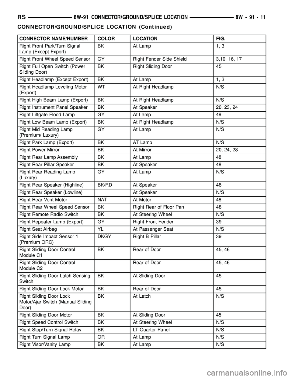
CONNECTOR NAME/NUMBER COLOR LOCATION FIG.
Right Front Park/Turn Signal
Lamp (Except Export)BK At Lamp 1, 3
Right Front Wheel Speed Sensor GY Right Fender Side Shield 3,10, 16, 17
Right Full Open Switch (Power
Sliding Door)BK Right Sliding Door 45
Right Headlamp (Except Export) BK At Lamp 1, 3
Right Headlamp Leveling Motor
(Export)WT At Right Headlamp N/S
Right High Beam Lamp (Export) BK At Right Headlamp N/S
Right Instrument Panel Speaker BK At Speaker 20, 23, 24
Right Liftgate Flood Lamp GY At Lamp 49
Right Low Beam Lamp (Export) BK At Right Headlamp N/S
Right Mid Reading Lamp
(Premium/ Luxury)GY At Lamp N/S
Right Park Lamp (Export) BK AT Lamp N/S
Right Power Mirror BK At Mirror 20, 24, 28
Right Rear Lamp Assembly BK At Lamp 48
Right Rear Pillar Speaker BK At Speaker 48
Right Rear Reading Lamp
(Luxury)GY At Lamp N/S
Right Rear Speaker (Highline) BK/RD At Speaker 48
Right Rear Speaker (Lowline) At Speaker N/S
Right Rear Vent Motor NAT At Motor 48
Right Rear Wheel Speed Sensor BK Right Rear of Floor Pan 48
Right Remote Radio Switch BK At Steering Wheel N/S
Right Repeater Lamp (Export) GY Right Front Fender 39
Right Seat Airbag YL At Passenger Seat N/S
Right Side Impact Sensor 1
(Premium ORC)DKGY Right B Pillar 39
Right Sliding Door Control
Module C1BK Rear of Door 45, 46
Right Sliding Door Control
Module C2Rear of Door 45, 46
Right Sliding Door Latch Sensing
SwitchBK At Sliding Door 45
Right Sliding Door Lock Motor BK Rear of Door 45
Right Sliding Door Lock
Motor/Ajar Switch (Manual Sliding
Door)BK At Latch N/S
Right Sliding Door Motor BK At Sliding Door 45
Right Speed Control Switch BK At Steering Wheel N/S
Right Stop/Turn Signal Relay BK LT Quarter Panel N/S
Right Turn Signal Lamp OR At Lamp N/S
Right Visor/Vanity Lamp BK At Lamp N/S
RS8W-91 CONNECTOR/GROUND/SPLICE LOCATION8W-91-11
CONNECTOR/GROUND/SPLICE LOCATION (Continued)
Page 1246 of 2585
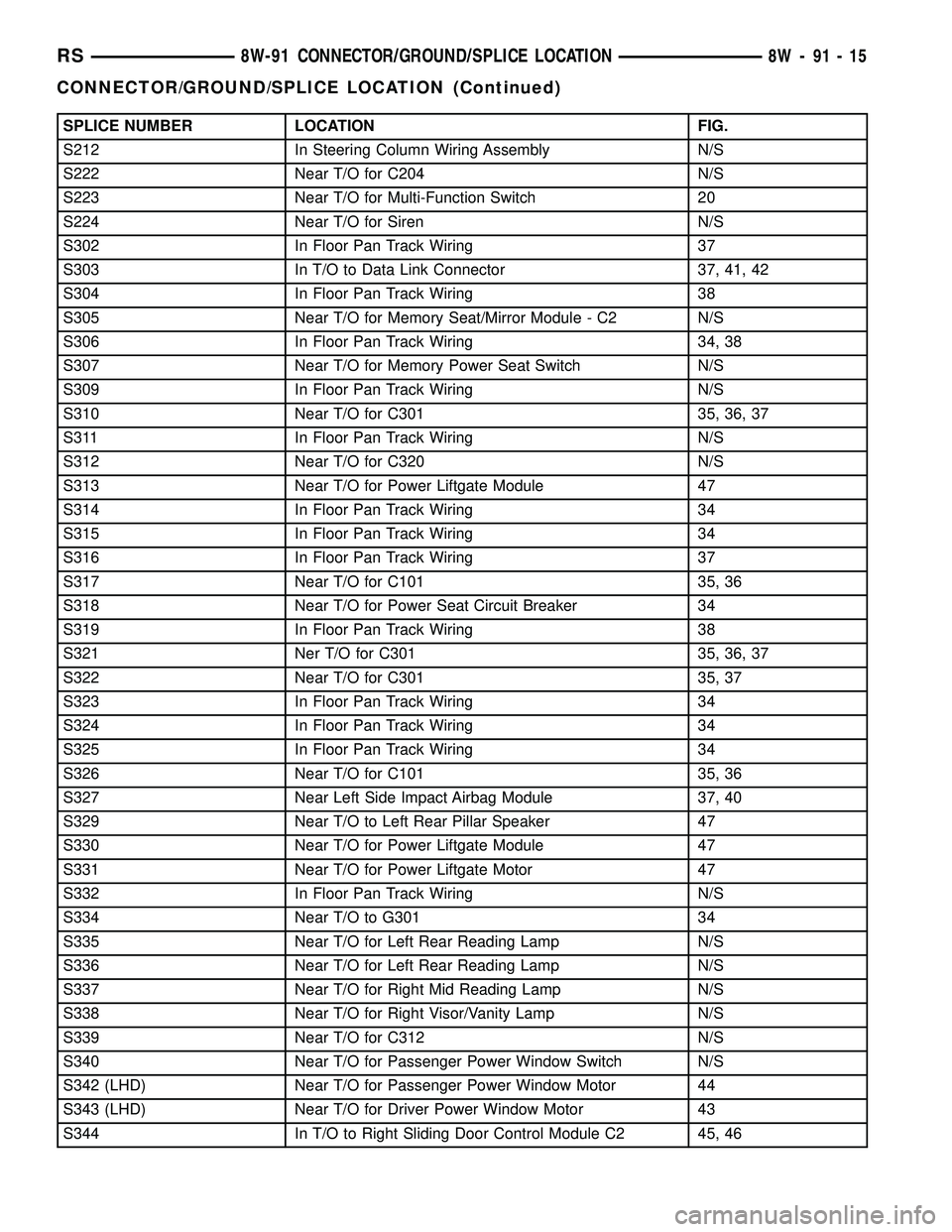
SPLICE NUMBER LOCATION FIG.
S212 In Steering Column Wiring Assembly N/S
S222 Near T/O for C204 N/S
S223 Near T/O for Multi-Function Switch 20
S224 Near T/O for Siren N/S
S302 In Floor Pan Track Wiring 37
S303 In T/O to Data Link Connector 37, 41, 42
S304 In Floor Pan Track Wiring 38
S305 Near T/O for Memory Seat/Mirror Module - C2 N/S
S306 In Floor Pan Track Wiring 34, 38
S307 Near T/O for Memory Power Seat Switch N/S
S309 In Floor Pan Track Wiring N/S
S310 Near T/O for C301 35, 36, 37
S311 In Floor Pan Track Wiring N/S
S312 Near T/O for C320 N/S
S313 Near T/O for Power Liftgate Module 47
S314 In Floor Pan Track Wiring 34
S315 In Floor Pan Track Wiring 34
S316 In Floor Pan Track Wiring 37
S317 Near T/O for C101 35, 36
S318 Near T/O for Power Seat Circuit Breaker 34
S319 In Floor Pan Track Wiring 38
S321 Ner T/O for C301 35, 36, 37
S322 Near T/O for C301 35, 37
S323 In Floor Pan Track Wiring 34
S324 In Floor Pan Track Wiring 34
S325 In Floor Pan Track Wiring 34
S326 Near T/O for C101 35, 36
S327 Near Left Side Impact Airbag Module 37, 40
S329 Near T/O to Left Rear Pillar Speaker 47
S330 Near T/O for Power Liftgate Module 47
S331 Near T/O for Power Liftgate Motor 47
S332 In Floor Pan Track Wiring N/S
S334 Near T/O to G301 34
S335 Near T/O for Left Rear Reading Lamp N/S
S336 Near T/O for Left Rear Reading Lamp N/S
S337 Near T/O for Right Mid Reading Lamp N/S
S338 Near T/O for Right Visor/Vanity Lamp N/S
S339 Near T/O for C312 N/S
S340 Near T/O for Passenger Power Window Switch N/S
S342 (LHD) Near T/O for Passenger Power Window Motor 44
S343 (LHD) Near T/O for Driver Power Window Motor 43
S344 In T/O to Right Sliding Door Control Module C2 45, 46
RS8W-91 CONNECTOR/GROUND/SPLICE LOCATION8W-91-15
CONNECTOR/GROUND/SPLICE LOCATION (Continued)
Page 1568 of 2585
SHROUD - UPPER
REMOVAL
(1) Remove the two shroud-to-shroud mounting
screws from the lower shroud (Fig. 32).
(2) Unsnap the upper shroud from the lower on
the left side as follows:
(a) Hook a finger on the left hand around the
rear of the shrouds at the seam (Fig. 33), near the
snap points.
(b) Grasp the upper shroud at the rear using the
right hand (Fig. 33).
(c) As the left hand's hooked finger is pulled out-
ward against the seam, pull the upper shroud
upward using the right hand, disconnecting the
shroud snaps.
(3) Unsnap the upper shroud from the lower on
the right side as follows:
(a) Hook a finger on the right hand around the
rear of the shrouds at the seam (Fig. 34), near the
snap points.
(b) Grasp the upper shroud at the rear using the
left hand (Fig. 34).
(c) As the right hand's hooked finger is pulled
outward against the seam, pull the upper shroud
upward using the left hand, disconnecting the
shroud snaps.
(4) Lift the upper shroud straight up off the steer-
ing column. If vehicle is equipped with traction con-
trol, disconnect wiring connector at traction control
switch pig tail. If vehicle is equipped with power fold-
away mirrors (Export), disconnect wiring connector
at mirror switch pig tail. Remove upper shroud.
(5) If vehicle is equipped with traction control,
remove traction control switch from shroud.
(6) If vehicle is equipped with power foldaway mir-
rors (Export), remove power fold-away switch from
upper shroud.
INSTALLATION
(1) If the vehicle is equipped with power foldaway
mirrors (Export), install the power fold-away switch
in the upper shroud.
(2) If vehicle is equipped with traction control,
install the traction control switch in the upper
shroud.
(3) Place the upper shroud over the lower shroud,
aligning the snap clips and alignment tabs. If the
vehicle is equipped with traction control, connect the
wiring connector at the traction control switch pig
tail before lining the shrouds up to one another.
(4) Snap the upper shroud to the lower shroud.
Once snapped into place, verify there are no gaps
between the two mating surfaces of the shrouds.(5) Install the two shroud-to-shroud mounting
screws (Fig. 32). Tighten the screws to 2 N´m (17 in.
lbs.) torque.
(6) Ensure that the shrouds are snug and fit is
acceptable.
STEERING WHEEL
REMOVAL
NOTE: Before proceeding, (Refer to 19 - STEERING/
COLUMN - WARNING)(Refer to 8 - ELECTRICAL/RE-
STRAINTS - WARNING).
(1) Adjust the steering wheel so that the tires are
in thestraight-aheadposition.
(2) Disconnect and isolate the battery negative
cable.
(3) Remove the two bolts from the rear of the
steering wheel attaching the driver airbag. Lift the
airbag from the steering wheel.
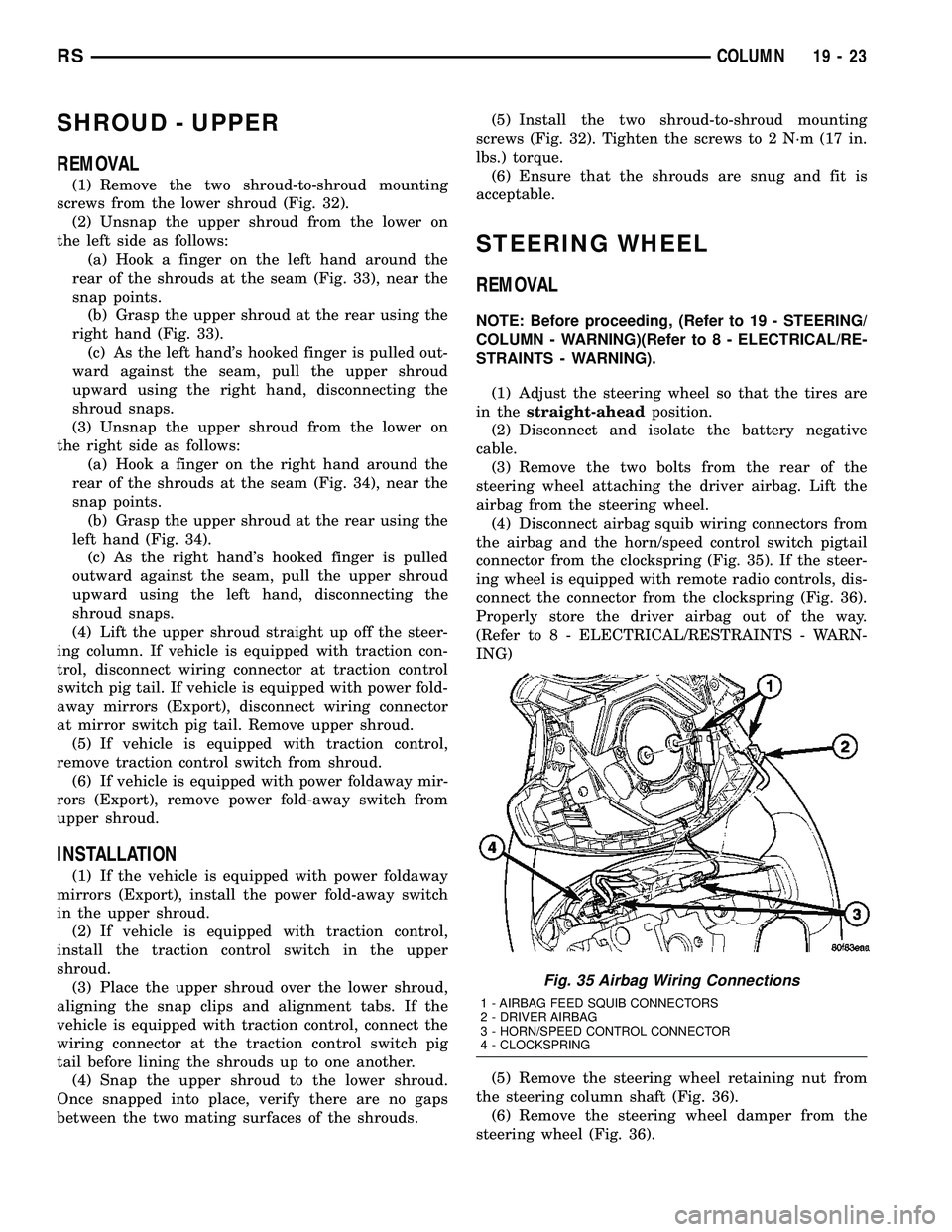
(4) Disconnect airbag squib wiring connectors from
the airbag and the horn/speed control switch pigtail
connector from the clockspring (Fig. 35). If the steer-
ing wheel is equipped with remote radio controls, dis-
connect the connector from the clockspring (Fig. 36).
Properly store the driver airbag out of the way.
(Refer to 8 - ELECTRICAL/RESTRAINTS - WARN-
ING)
(5) Remove the steering wheel retaining nut from
the steering column shaft (Fig. 36).
(6) Remove the steering wheel damper from the
steering wheel (Fig. 36).
Fig. 35 Airbag Wiring Connections
1 - AIRBAG FEED SQUIB CONNECTORS
2 - DRIVER AIRBAG
3 - HORN/SPEED CONTROL CONNECTOR
4 - CLOCKSPRING
RSCOLUMN19-23