2004 CHRYSLER VOYAGER ESP
[x] Cancel search: ESPPage 1382 of 2585
anaerobic material is for use between two machined
surfaces. Do not use on flexible metal flanges.
MOPARtBED PLATE SEALANTis a unique
(green-in-color) anaerobic type gasket material that
is specially made to seal the area between the bed-
plate and cylinder block without disturbing the bear-
ing clearance or alignment of these components. The
material cures slowly in the absence of air when
torqued between two metallic surfaces, and will rap-
idly cure when heat is applied.
MOPARtGASKET SEALANTis a slow drying,
permanently soft sealer. This material is recom-
mended for sealing threaded fittings and gaskets
against leakage of oil and coolant. Can be used on
threaded and machined parts under all tempera-
tures. This material is used on engines with multi-
layer steel (MLS) cylinder head gaskets. This
material also will prevent corrosion. MopartGasket
Sealant is available in a 13 oz. aerosol can or 4oz./16
oz. can w/applicator.
SEALER APPLICATION
MopartGasket Maker material should be applied
sparingly 1 mm (0.040 in.) diameter or less of sealant
to one gasket surface. Be certain the material sur-
rounds each mounting hole. Excess material can eas-
ily be wiped off. Components should be torqued in
place within 15 minutes. The use of a locating dowel
is recommended during assembly to prevent smear-
ing material off the location.
MopartEngine RTV GEN II or ATF RTV gasket
material should be applied in a continuous bead
approximately 3 mm (0.120 in.) in diameter. All
mounting holes must be circled. For corner sealing, a
3.17 or 6.35 mm (1/8 or 1/4 in.) drop is placed in the
center of the gasket contact area. Uncured sealant
may be removed with a shop towel. Components
should be torqued in place while the sealant is still
wet to the touch (within 10 minutes). The usage of a
locating dowel is recommended during assembly to
prevent smearing material off the location.
MopartGasket Sealant in an aerosol can should be
applied using a thin, even coat sprayed completely
over both surfaces to be joined, and both sides of a
gasket. Then proceed with assembly. Material in a
can w/applicator can be brushed on evenly over the
sealing surfaces. Material in an aerosol can should be
used on engines with multi-layer steel gaskets.
STANDARD PROCEDURE - ENGINE GASKET
SURFACE PREPARATION
To ensure engine gasket sealing, proper surface
preparation must be performed, especially with the
use of aluminum engine components and multi-layer
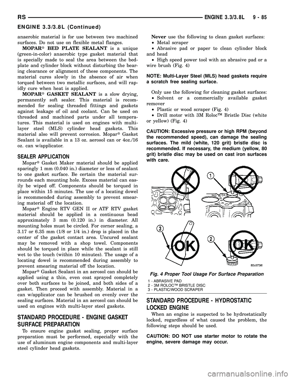
steel cylinder head gaskets.Neveruse the following to clean gasket surfaces:
²Metal scraper
²Abrasive pad or paper to clean cylinder block
and head
²High speed power tool with an abrasive pad or a
wire brush (Fig. 4)
NOTE: Multi-Layer Steel (MLS) head gaskets require
a scratch free sealing surface.
Only use the following for cleaning gasket surfaces:
²Solvent or a commercially available gasket
remover
²Plastic or wood scraper (Fig. 4)
²Drill motor with 3M RolocŸ Bristle Disc (white
or yellow) (Fig. 4)
CAUTION: Excessive pressure or high RPM (beyond
the recommended speed), can damage the sealing
surfaces. The mild (white, 120 grit) bristle disc is
recommended. If necessary, the medium (yellow, 80
grit) bristle disc may be used on cast iron surfaces
with care.
STANDARD PROCEDURE - HYDROSTATIC
LOCKED ENGINE
When an engine is suspected to be hydrostatically
locked, regardless of what caused the problem, the
following steps should be used.
CAUTION: DO NOT use starter motor to rotate the
engine, severe damage may occur.
Fig. 4 Proper Tool Usage For Surface Preparation
1 - ABRASIVE PAD
2 - 3M ROLOCŸ BRISTLE DISC
3 - PLASTIC/WOOD SCRAPER
RSENGINE 3.3/3.8L9-85
ENGINE 3.3/3.8L (Continued)
Page 1397 of 2585
CHEMICAL TEST METHOD
Combustion leaks into the cooling system can also
be checked by using Bloc-Chek Kit C-3685-A or
equivalent. Perform test following the procedures
supplied with the tool kit.
REMOVAL - CYLINDER HEAD
(1) Drain the cooling system. (Refer to 7 - COOL-
ING - STANDARD PROCEDURE)
(2) Disconnect negative cable from battery.
(3) Remove upper and lower intake manifolds.
(Refer to 9 - ENGINE/MANIFOLDS/INTAKE MANI-
FOLD - REMOVAL)
WARNING: INTAKE MANIFOLD GASKET IS MADE
OF VERY THIN METAL AND MAY CAUSE PER-
SONAL INJURY, HANDLE WITH CARE.
(4) Remove the cylinder head covers. (Refer to 9 -
ENGINE/CYLINDER HEAD/CYLINDER HEAD
COVER(S) - REMOVAL)
(5) Remove the spark plugs from cylinder head.(6) Remove the dipstick and tube (Fig. 18).
(7) Remove exhaust manifold(s). (Refer to 9 -
ENGINE/MANIFOLDS/EXHAUST MANIFOLD -
REMOVAL)
(8) Remove rocker arm and shaft assemblies.(Refer
to 9 - ENGINE/CYLINDER HEAD/ROCKER ARMS -
REMOVAL) Remove push rods andmark positions
to ensure installation in original locations.
(9) Remove the eight head bolts from each cylinder
head and remove cylinder heads (Fig. 22).
CLEANING
To ensure engine gasket sealing, proper surface
preparation must be performed, especially with the
use of aluminum engine components and multi-layer
steel cylinder head gaskets.
NOTE: Multi-Layer Steel (MLS) head gaskets require
a scratch free sealing surface.
Remove all gasket material from cylinder head and
block (Refer to 9 - ENGINE - STANDARD PROCE-
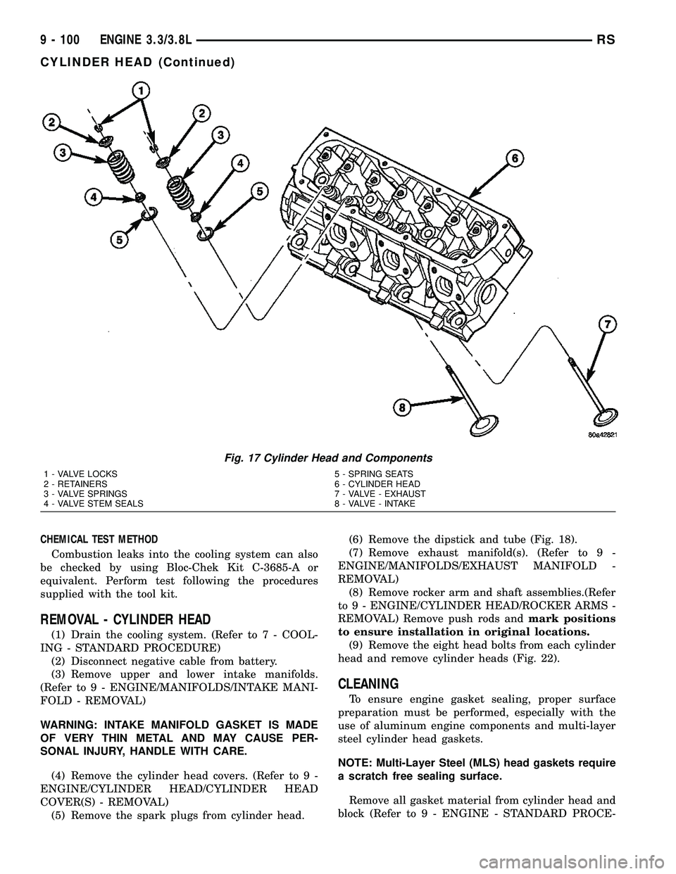
Fig. 17 Cylinder Head and Components
1 - VALVE LOCKS 5 - SPRING SEATS
2 - RETAINERS 6 - CYLINDER HEAD
3 - VALVE SPRINGS 7 - VALVE - EXHAUST
4 - VALVE STEM SEALS 8 - VALVE - INTAKE
9 - 100 ENGINE 3.3/3.8LRS
CYLINDER HEAD (Continued)
Page 1472 of 2585
CYLINDER-TO-WATER JACKET LEAKAGE TEST
WARNING: USE EXTREME CAUTION WHEN THE
ENGINE IS OPERATING WITH COOLANT PRES-
SURE CAP REMOVED.
VISUAL TEST METHOD
With the engine cool, remove the coolant pressure
cap. Start the engine and allow it to warm up until
thermostat opens.
If a large combustion/compression pressure leak
exists, bubbles will be visible in the coolant.
COOLING SYSTEM TESTER METHOD
WARNING: WITH COOLING SYSTEM TESTER IN
PLACE, PRESSURE WILL BUILD UP FAST. EXCES-
SIVE PRESSURE BUILT UP, BY CONTINUOUS
ENGINE OPERATION, MUST BE RELEASED TO A
SAFE PRESSURE POINT. NEVER PERMIT PRES-
SURE TO EXCEED 138 kPa (20 psi).
Install Cooling System Tester 7700 or equivalent to
pressure cap neck. Start the engine and observe the
tester's pressure gauge. If gauge pulsates with every
power stroke of a cylinder a combustion pressure
leak is evident.
CHEMICAL TEST METHOD
Combustion leaks into the cooling system can also
be checked by using Bloc-Chek Kit C-3685-A or
equivalent. Perform test following the procedures
supplied with the tool kit.
REMOVAL - CYLINDER HEAD
(1) Drain the cooling system. (Refer to 7 - COOL-
ING - STANDARD PROCEDURE)
(2) Disconnect negative cable from battery.
(3) Remove upper and lower intake manifolds.
(Refer to 9 - ENGINE/MANIFOLDS/INTAKE MANI-
FOLD - REMOVAL)
WARNING: INTAKE MANIFOLD GASKET IS MADE
OF VERY THIN METAL AND MAY CAUSE PER-
SONAL INJURY, HANDLE WITH CARE.
(4) Remove the cylinder head covers. (Refer to 9 -
ENGINE/CYLINDER HEAD/CYLINDER HEAD
COVER(S) - REMOVAL)
(5) Remove the spark plugs from cylinder head.
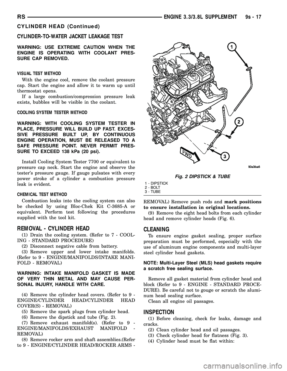
(6) Remove the dipstick and tube (Fig. 2).
(7) Remove exhaust manifold(s). (Refer to 9 -
ENGINE/MANIFOLDS/EXHAUST MANIFOLD -
REMOVAL)
(8) Remove rocker arm and shaft assemblies.(Refer
to 9 - ENGINE/CYLINDER HEAD/ROCKER ARMS -REMOVAL) Remove push rods andmark positions
to ensure installation in original locations.
(9) Remove the eight head bolts from each cylinder
head and remove cylinder heads (Fig. 6).
CLEANING
To ensure engine gasket sealing, proper surface
preparation must be performed, especially with the
use of aluminum engine components and multi-layer
steel cylinder head gaskets.
NOTE: Multi-Layer Steel (MLS) head gaskets require
a scratch free sealing surface.
Remove all gasket material from cylinder head and
block (Refer to 9 - ENGINE - STANDARD PROCE-
DURE). Be careful not to gouge or scratch the alumi-
num head sealing surface.
Clean all engine oil passages.
INSPECTION
(1) Before cleaning, check for leaks, damage and
cracks.
(2) Clean cylinder head and oil passages.
(3) Check cylinder head for flatness (Fig. 3).
(4) Cylinder head must be flat within:
Fig. 2 DIPSTICK & TUBE
1 - DIPSTICK
2 - BOLT
3 - TUBE
RSENGINE 3.3/3.8L SUPPLEMENT9s-17
CYLINDER HEAD (Continued)
Page 1480 of 2585
(7) Install a spark plug adapter in the spark plug
hole. Connect air hose that can supply 620.5±689 kPa
(90±100 psi) of air pressure to adapter. This is to
hold valves in place while servicing components.
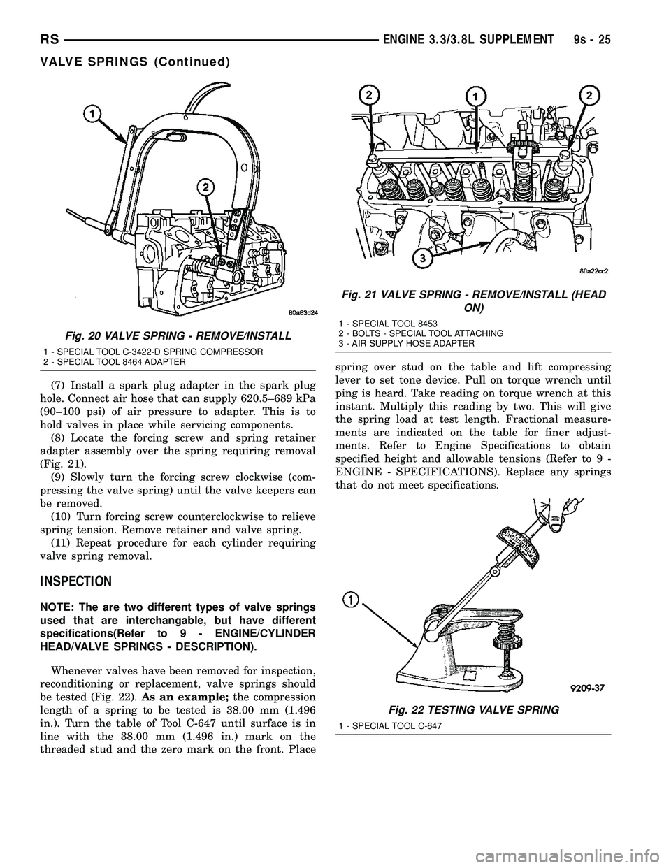
(8) Locate the forcing screw and spring retainer
adapter assembly over the spring requiring removal
(Fig. 21).
(9) Slowly turn the forcing screw clockwise (com-
pressing the valve spring) until the valve keepers can
be removed.
(10) Turn forcing screw counterclockwise to relieve
spring tension. Remove retainer and valve spring.
(11) Repeat procedure for each cylinder requiring
valve spring removal.
INSPECTION
NOTE: The are two different types of valve springs
used that are interchangable, but have different
specifications(Refer to 9 - ENGINE/CYLINDER
HEAD/VALVE SPRINGS - DESCRIPTION).
Whenever valves have been removed for inspection,
reconditioning or replacement, valve springs should
be tested (Fig. 22).As an example;the compression
length of a spring to be tested is 38.00 mm (1.496
in.). Turn the table of Tool C-647 until surface is in
line with the 38.00 mm (1.496 in.) mark on the
threaded stud and the zero mark on the front. Placespring over stud on the table and lift compressing
lever to set tone device. Pull on torque wrench until
ping is heard. Take reading on torque wrench at this
instant. Multiply this reading by two. This will give
the spring load at test length. Fractional measure-
ments are indicated on the table for finer adjust-
ments. Refer to Engine Specifications to obtain
specified height and allowable tensions (Refer to 9 -
ENGINE - SPECIFICATIONS). Replace any springs
that do not meet specifications.
Fig. 20 VALVE SPRING - REMOVE/INSTALL
1 - SPECIAL TOOL C-3422-D SPRING COMPRESSOR
2 - SPECIAL TOOL 8464 ADAPTER
Fig. 21 VALVE SPRING - REMOVE/INSTALL (HEAD
ON)
1 - SPECIAL TOOL 8453
2 - BOLTS - SPECIAL TOOL ATTACHING
3 - AIR SUPPLY HOSE ADAPTER
Fig. 22 TESTING VALVE SPRING
1 - SPECIAL TOOL C-647
RSENGINE 3.3/3.8L SUPPLEMENT9s-25
VALVE SPRINGS (Continued)
Page 1525 of 2585
FUEL INJECTION
OPERATION
OPERATION - INJECTION SYSTEM
All engines used in this section have a sequential
Multi-Port Electronic Fuel Injection system. The MPI
system is computer regulated and provides precise
air/fuel ratios for all driving conditions. The Power-
train Control Module (PCM) operates the fuel injec-
tion system.
The PCM regulates:
²Ignition timing
²Air/fuel ratio
²Emission control devices
²Cooling fan
²Charging system
²Idle speed
²Vehicle speed control
Various sensors provide the inputs necessary for
the PCM to correctly operate these systems. In addi-
tion to the sensors, various switches also provide
inputs to the PCM.
The PCM can adapt its programming to meet
changing operating conditions.
Fuel is injected into the intake port above the
intake valve in precise metered amounts through
electrically operated injectors. The PCM fires the
injectors in a specific sequence. Under most operat-
ing conditions, the PCM maintains an air fuel ratio
of 14.7 parts air to 1 part fuel by constantly adjust-
ing injector pulse width. Injector pulse width is the
length of time the injector is open.
The PCM adjusts injector pulse width by opening
and closing the ground path to the injector. Engine
RPM (speed) and manifold absolute pressure (air
density) are theprimaryinputs that determine
injector pulse width.
OPERATION - MODES OF OPERATION
As input signals to the PCM change, the PCM
adjusts its response to output devices. For example,
the PCM must calculate a different injector pulse
width and ignition timing for idle than it does for
Wide Open Throttle (WOT). There are several differ-
ent modes of operation that determine how the PCM
responds to the various input signals.
There are two different areas of operation, OPEN
LOOP and CLOSED LOOP.
During OPEN LOOP modes the PCM receives
input signals and responds according to preset PCM
programming. Inputs from the upstream and down-
stream heated oxygen sensors are not monitored dur-
ing OPEN LOOP modes, except for heated oxygensensor diagnostics (they are checked for shorted con-
ditions at all times).
During CLOSED LOOP modes the PCM monitors
the inputs from the upstream and downstream
heated oxygen sensors. The upstream heated oxygen
sensor input tells the PCM if the calculated injector
pulse width resulted in the ideal air-fuel ratio of 14.7
to one. By monitoring the exhaust oxygen content
through the upstream heated oxygen sensor, the
PCM can fine tune injector pulse width. Fine tuning
injector pulse width allows the PCM to achieve opti-
mum fuel economy combined with low emissions.
For the PCM to enter CLOSED LOOP operation,
the following must occur:
(1) Engine coolant temperature must be over 35ÉF.
²If the coolant is over 35ÉF the PCM will wait 38
seconds.
²If the coolant is over 50ÉF the PCM will wait 15
seconds.
²If the coolant is over 167ÉF the PCM will wait 3
seconds.
(2) For other temperatures the PCM will interpo-
late the correct waiting time.
(3) O2 sensor must read either greater than 0.745
volts or less than 0.29 volt.
(4) The multi-port fuel injection systems has the
following modes of operation:
²Ignition switch ON (Zero RPM)
²Engine start-up
²Engine warm-up
²Cruise
²Idle
²Acceleration
²Deceleration
²Wide Open Throttle
²Ignition switch OFF
(5) The engine start-up (crank), engine warm-up,
deceleration with fuel shutoff and wide open throttle
modes are OPEN LOOP modes. Under most operat-
ing conditions, the acceleration, deceleration (with
A/C on), idle and cruise modes,with the engine at
operating temperatureare CLOSED LOOP modes.
IGNITION SWITCH ON (ZERO RPM) MODE
When the ignition switch activates the fuel injec-
tion system, the following actions occur:
²The PCM monitors the engine coolant tempera-
ture sensor and throttle position sensor input. The
PCM determines basic fuel injector pulse width from
this input.
²The PCM determines atmospheric air pressure
from the MAP sensor input to modify injector pulse
width.
When the key is in the ON position and the engine
is not running (zero rpm), the Auto Shutdown (ASD)
and fuel pump relays de-energize after approximately
14 - 18 FUEL INJECTIONRS
Page 1527 of 2585
²All monitored components (refer to the Emission
section for On-Board Diagnostics).
The PCM compares the upstream and downstream
heated oxygen sensor inputs to measure catalytic
convertor efficiency. If the catalyst efficiency drops
below the minimum acceptable percentage, the PCM
stores a diagnostic trouble code in memory, after 2
trips.
During certain idle conditions, the PCM may enter
a variable idle speed strategy. During variable idle
speed strategy the PCM adjusts engine speed based
on the following inputs.
²A/C status
²Battery voltage
²Battery temperature or Calculated Battery Tem-
perature
²Engine coolant temperature
²Engine run time
²Inlet/Intake air temperature
²Vehicle mileage
ACCELERATION MODE
This is a CLOSED LOOP mode. The PCM recog-
nizes an abrupt increase in Throttle Position sensor
output voltage or MAP sensor output voltage as a
demand for increased engine output and vehicle
acceleration. The PCM increases injector pulse width
in response to increased fuel demand.
²Wide Open Throttle-open loop
DECELERATION MODE
This is a CLOSED LOOP mode. During decelera-
tion the following inputs are received by the PCM:
²A/C status
²Battery voltage
²Inlet/Intake air temperature
²Engine coolant temperature
²Crankshaft position (engine speed)
²Exhaust gas oxygen content (upstream heated
oxygen sensor)
²Knock sensor
²Manifold absolute pressure
²Throttle position sensor
²IAC motor (solenoid) control changes in response
to MAP sensor feedback
The PCM may receive a closed throttle input from
the Throttle Position Sensor (TPS) when it senses an
abrupt decrease in manifold pressure. This indicates
a hard deceleration (Open Loop). In response, the
PCM may momentarily turn off the injectors. This
helps improve fuel economy, emissions and engine
braking.
WIDE-OPEN-THROTTLE MODE
This is an OPEN LOOP mode. During wide-open-
throttle operation, the following inputs are used by
the PCM:
²Inlet/Intake air temperature
²Engine coolant temperature
²Engine speed
²Knock sensor
²Manifold absolute pressure
²Throttle position
When the PCM senses a wide-open-throttle condi-
tion through the Throttle Position Sensor (TPS) it de-
energizes the A/C compressor clutch relay. This
disables the air conditioning system and disables
EGR (if equipped).
The PCM adjusts injector pulse width to supply a
predetermined amount of additional fuel, based on
MAP and RPM.
IGNITION SWITCH OFF MODE
When the operator turns the ignition switch to the
OFF position, the following occurs:
²All outputs are turned off, unless 02 Heater
Monitor test is being run. Refer to the Emission sec-
tion for On-Board Diagnostics.
²No inputs are monitored except for the heated
oxygen sensors. The PCM monitors the heating ele-
ments in the oxygen sensors and then shuts down.
FUEL CORRECTION or ADAPTIVE MEMORIES
DESCRIPTION
In Open Loop, the PCM changes pulse width with-
out feedback from the O2 Sensors. Once the engine
warms up to approximately 30 to 35É F, the PCM
goes into closed loopShort Term Correctionand
utilizes feedback from the O2 Sensors. Closed loop
Long Term Adaptive Memoryis maintained above
170É to 190É F unless the PCM senses wide open
throttle. At that time the PCM returns to Open Loop
operation.
OPERATION
Short Term
The first fuel correction program that begins func-
tioning is the short term fuel correction. This system
corrects fuel delivery in direct proportion to the read-
ings from the Upstream O2 Sensor.
The PCM monitors the air/fuel ratio by using the
input voltage from the O2 Sensor. When the voltage
reaches its preset high or low limit, the PCM begins
to add or remove fuel until the sensor reaches its
switch point. The short term corrections then begin.
The PCM makes a series of quick changes in the
injector pulse-width until the O2 Sensor reaches its
14 - 20 FUEL INJECTIONRS
FUEL INJECTION (Continued)
Page 1538 of 2585
weather, high pressure area. This is important
because as air pressure changes the barometric pres-
sure changes. Barometric pressure and altitude have
a direct inverse correlation, as altitude goes up baro-
metric goes down. The first thing that happens as
the key is rolled on, before reaching the crank posi-
tion, the PCM powers up, comes around and looks at
the MAP voltage, and based upon the voltage it sees,
it knows the current barometric pressure relative to
altitude. Once the engine starts, the PCM looks at
the voltage again, continuously every 12 milliseconds,
and compares the current voltage to what it was at
key on. The difference between current and what it
was at key on is manifold vacuum.
During key On (engine not running) the sensor
reads (updates) barometric pressure. A normal range
can be obtained by monitoring known good sensor in
you work area.
As the altitude increases the air becomes thinner
(less oxygen). If a vehicle is started and driven to a
very different altitude than where it was at key On
the barometric pressure needs to be updated. Any
time the PCM sees Wide Open throttle, based upon
TPS angle and RPM it will update barometric pres-
sure in the MAP memory cell. With periodic updates,
the PCM can make its calculations more effectively.
The PCM uses the MAP sensor to aid in calculat-
ing the following:
²Barometric pressure
²Engine load
²Manifold pressure
²Injector pulse-width
²Spark-advance programs
²Shift-point strategies (F4AC1 transmissions
only, via the PCI bus)
²Idle speed²Decel fuel shutoff
The PCM recognizes a decrease in manifold pres-
sure by monitoring a decrease in voltage from the
reading stored in the barometric pressure memory
cell. The MAP sensor is a linear sensor; as pressure
changes, voltage changes proportionately. The range
of voltage output from the sensor is usually between
4.6 volts at sea level to as low as 0.3 volts at 26 in. of
Hg. Barometric pressure is the pressure exerted by
the atmosphere upon an object. At sea level on a
standard day, no storm, barometric pressure is 29.92
in Hg. For every 100 feet of altitude barometric pres-
sure drops .10 in. Hg. If a storm goes through it can
either add, high pressure, or decrease, low pressure,
from what should be present for that altitude. You
should make a habit of knowing what the average
pressure and corresponding barometric pressure is
for your area.REMOVAL
REMOVAL - 2.4L
(1) Disconnect the negative battery cable.
(2) Disconnect electrical connector and vacuum
hose from MAP sensor (Fig. 20).
(3) Remove two screws holding sensor to the
intake manifold.
REMOVAL - 3.3/3.8L
(1) Disconnect the negative battery cable.
(2) Remove vacuum hose and mounting screws
from manifold absolute pressure (MAP) sensor (Fig.
21).
(3) Disconnect electrical connector from sensor.
Remove sensor.
INSTALLATION
INSTALLATION - 2.4L
(1) Install sensor.
(2) Install two screws and tighten.
(3) Connect the electrical connector and vacuum
hose to the MAP sensor (Fig. 20).
(4) Connect the negative battery cable.
INSTALLATION - 3.3/3.8L
(1) Install sensor (Fig. 21).
(2) Install screws and tighten toPLASTIC MAN-
IFOLD 1.7 N´m (15 in. lbs.) ALUMINUM MANI-
FOLD 3.3 N´m (30 in. lbs.).
(3) Connect the electrical connector to the sensor.
Install vacuum hose.
(4) Connect the negative battery cable.
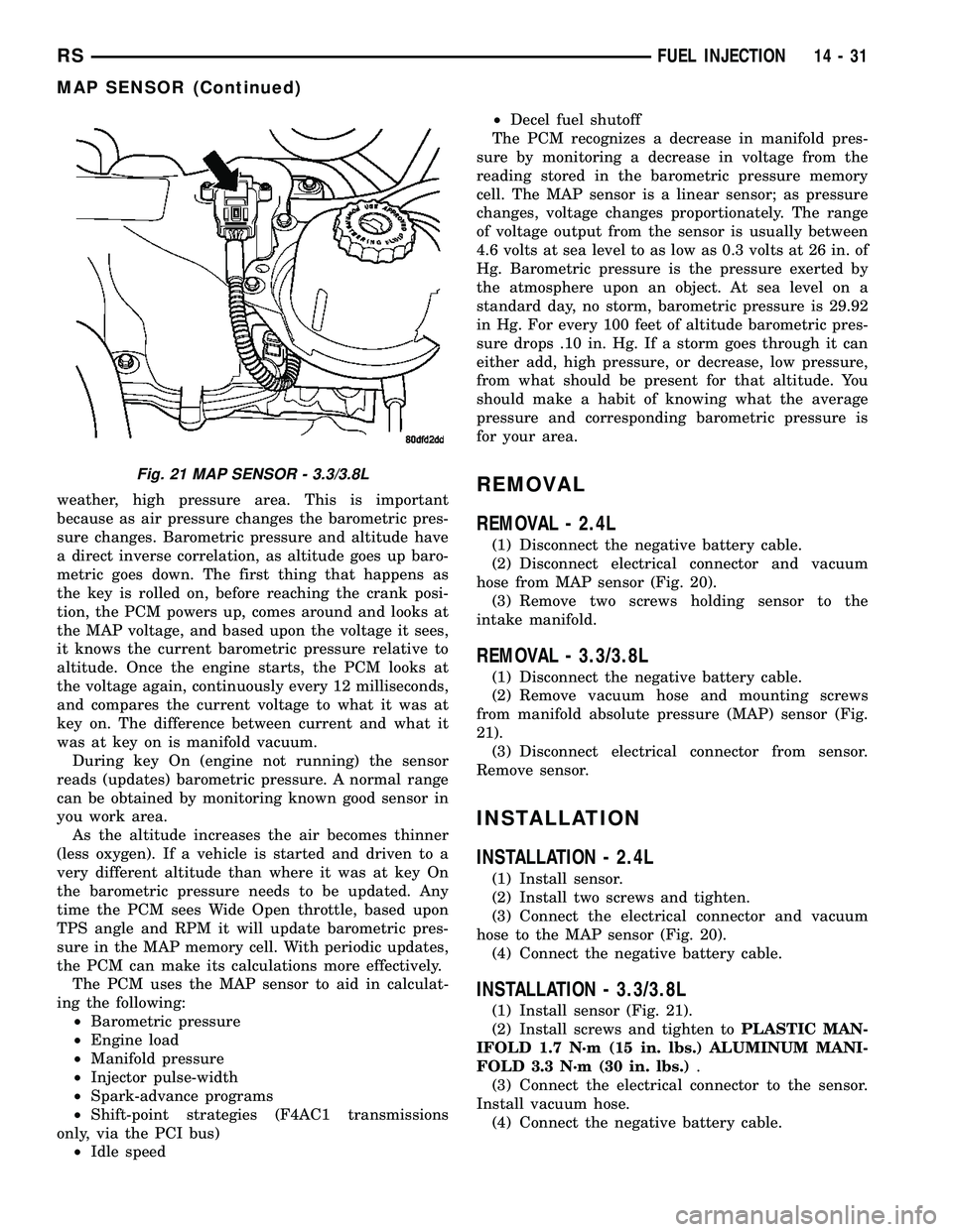
Fig. 21 MAP SENSOR - 3.3/3.8L
RSFUEL INJECTION14-31
MAP SENSOR (Continued)
Page 1546 of 2585
STEERING
TABLE OF CONTENTS
page page
STEERING
DESCRIPTION - POWER STEERING SYSTEM . . 1
OPERATION - POWER STEERING SYSTEM . . . 1
DIAGNOSIS AND TESTING
DIAGNOSIS AND TESTING - POWER
STEERING SYSTEM FLOW AND
PRESSURE TEST......................1
DIAGNOSIS AND TESTING - STEERING
SYSTEM DIAGNOSIS CHARTS............3SPECIFICATIONS
POWER STEERING FASTENER TORQUE . . . 9
SPECIAL TOOLS
POWER STEERING....................9
COLUMN..............................10
GEAR.................................26
PUMP.................................36
STEERING
DESCRIPTION - POWER STEERING SYSTEM
This vehicle comes with power steering as stan-
dard equipment. The power steering system consists
of these major components:
²POWER STEERING PUMP
²POWER STEERING GEAR
²POWER STEERING FLUID
²POWER STEERING FLUID COOLER
²POWER STEERING FLUID RESERVOIR
²POWER STEERING FLUID SUPPLY HOSE
²POWER STEERING FLUID PRESSURE HOSE
²POWER STEERING FLUID RETURN HOSE
For information on the first two components, refer
to their respective sections within this service man-
ual group. Information on all other components can
be found in POWER STEERING PUMP.
OPERATION - POWER STEERING SYSTEM
Turning of the steering wheel is converted into lin-
ear (side-to-side) travel through the meshing of the
helical pinion teeth with the rack teeth within the
steering gear. The lateral travel pushes and pulls the
tie rods to change the direction of the vehicle's front
wheels.
Power assist steering is provided by a belt driven
rotary type pump. It directs fluid through power
steering fluid hoses to the power steering gear where
it is used to assist the driver's turning effort.
Manual steering control of the vehicle can be main-
tained if power steering assist is lost. However,
under this condition, steering effort is significantly
increased.
DIAGNOSIS AND TESTING
DIAGNOSIS AND TESTING - POWER STEERING
SYSTEM FLOW AND PRESSURE TEST
ALL ENGINES
The following procedure is to be used to test the
operation of the power steering system on this vehi-
cle. This test will provide the flow rate of the power
steering pump along with the maximum relief pres-
sure. This test is to be performed to determine if the
power steering pump or power steering gear is not
functioning properly. The following flow and pressure
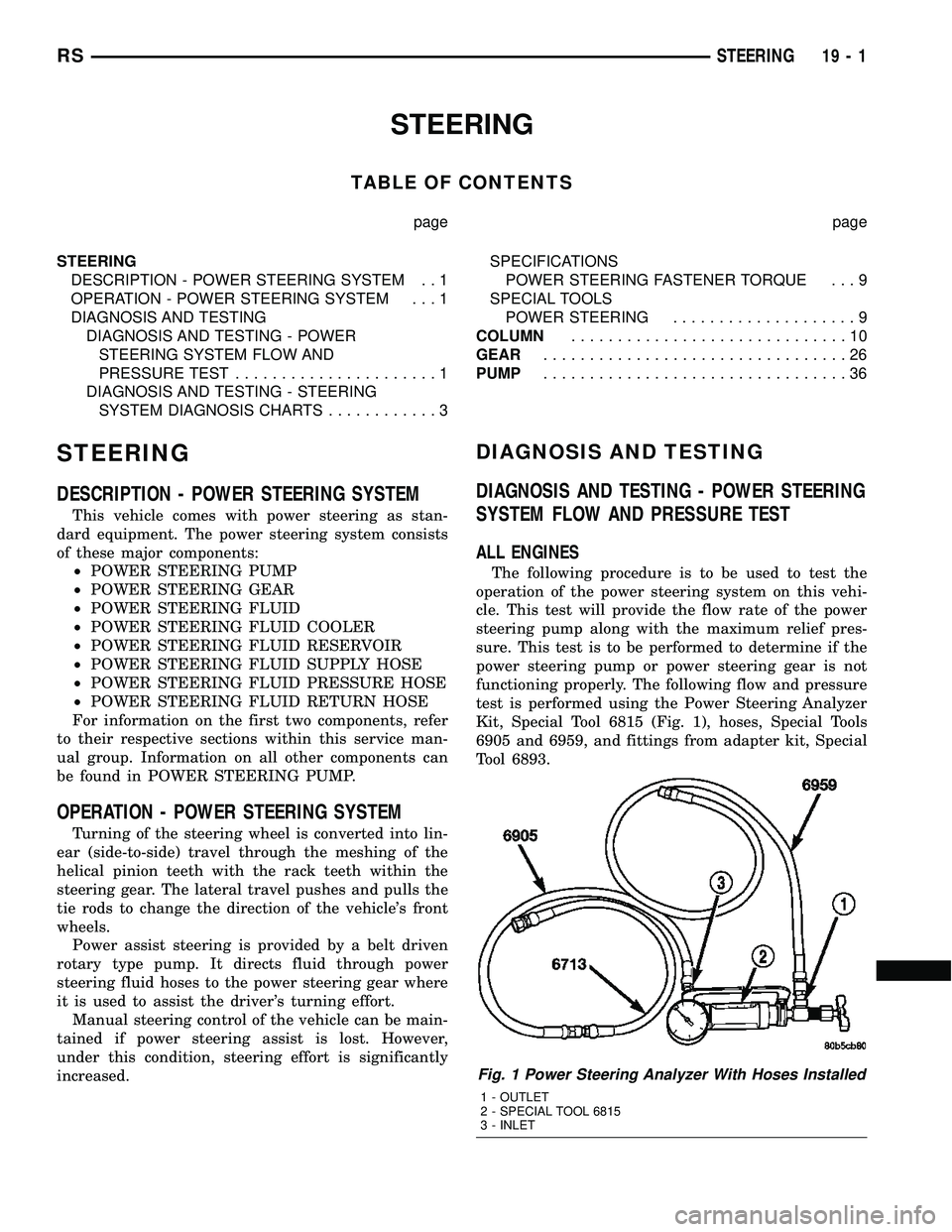
test is performed using the Power Steering Analyzer
Kit, Special Tool 6815 (Fig. 1), hoses, Special Tools
6905 and 6959, and fittings from adapter kit, Special
Tool 6893.
Fig. 1 Power Steering Analyzer With Hoses Installed
1 - OUTLET
2 - SPECIAL TOOL 6815
3 - INLET
RSSTEERING19-1