2004 CHRYSLER VOYAGER engine
[x] Cancel search: enginePage 1479 of 2585
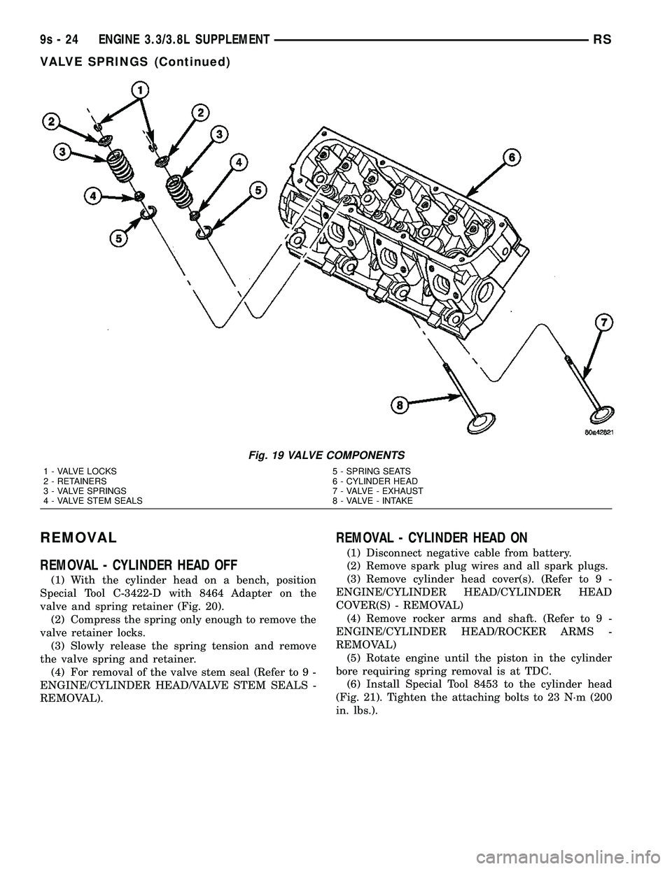
REMOVAL
REMOVAL - CYLINDER HEAD OFF
(1) With the cylinder head on a bench, position
Special Tool C-3422-D with 8464 Adapter on the
valve and spring retainer (Fig. 20).
(2) Compress the spring only enough to remove the
valve retainer locks.
(3) Slowly release the spring tension and remove
the valve spring and retainer.
(4) For removal of the valve stem seal (Refer to 9 -
ENGINE/CYLINDER HEAD/VALVE STEM SEALS -
REMOVAL).
REMOVAL - CYLINDER HEAD ON
(1) Disconnect negative cable from battery.
(2) Remove spark plug wires and all spark plugs.
(3) Remove cylinder head cover(s). (Refer to 9 -
ENGINE/CYLINDER HEAD/CYLINDER HEAD
COVER(S) - REMOVAL)
(4) Remove rocker arms and shaft. (Refer to 9 -
ENGINE/CYLINDER HEAD/ROCKER ARMS -
REMOVAL)
(5) Rotate engine until the piston in the cylinder
bore requiring spring removal is at TDC.
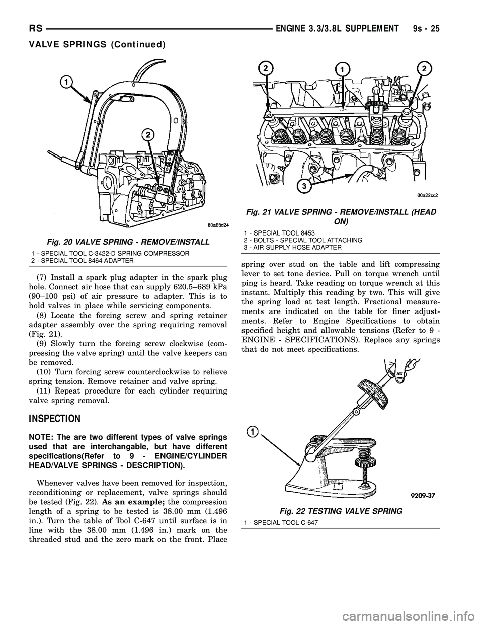
(6) Install Special Tool 8453 to the cylinder head
(Fig. 21). Tighten the attaching bolts to 23 N´m (200
in. lbs.).
Fig. 19 VALVE COMPONENTS
1 - VALVE LOCKS 5 - SPRING SEATS
2 - RETAINERS 6 - CYLINDER HEAD
3 - VALVE SPRINGS 7 - VALVE - EXHAUST
4 - VALVE STEM SEALS 8 - VALVE - INTAKE
9s - 24 ENGINE 3.3/3.8L SUPPLEMENTRS
VALVE SPRINGS (Continued)
Page 1480 of 2585
(7) Install a spark plug adapter in the spark plug
hole. Connect air hose that can supply 620.5±689 kPa
(90±100 psi) of air pressure to adapter. This is to
hold valves in place while servicing components.
(8) Locate the forcing screw and spring retainer
adapter assembly over the spring requiring removal
(Fig. 21).
(9) Slowly turn the forcing screw clockwise (com-
pressing the valve spring) until the valve keepers can
be removed.
(10) Turn forcing screw counterclockwise to relieve
spring tension. Remove retainer and valve spring.
(11) Repeat procedure for each cylinder requiring
valve spring removal.
INSPECTION
NOTE: The are two different types of valve springs
used that are interchangable, but have different
specifications(Refer to 9 - ENGINE/CYLINDER
HEAD/VALVE SPRINGS - DESCRIPTION).
Whenever valves have been removed for inspection,
reconditioning or replacement, valve springs should
be tested (Fig. 22).As an example;the compression
length of a spring to be tested is 38.00 mm (1.496
in.). Turn the table of Tool C-647 until surface is in
line with the 38.00 mm (1.496 in.) mark on the
threaded stud and the zero mark on the front. Placespring over stud on the table and lift compressing
lever to set tone device. Pull on torque wrench until
ping is heard. Take reading on torque wrench at this
instant. Multiply this reading by two. This will give
the spring load at test length. Fractional measure-
ments are indicated on the table for finer adjust-
ments. Refer to Engine Specifications to obtain
specified height and allowable tensions (Refer to 9 -
ENGINE - SPECIFICATIONS). Replace any springs
that do not meet specifications.
Fig. 20 VALVE SPRING - REMOVE/INSTALL
1 - SPECIAL TOOL C-3422-D SPRING COMPRESSOR
2 - SPECIAL TOOL 8464 ADAPTER
Fig. 21 VALVE SPRING - REMOVE/INSTALL (HEAD
ON)
1 - SPECIAL TOOL 8453
2 - BOLTS - SPECIAL TOOL ATTACHING
3 - AIR SUPPLY HOSE ADAPTER
Fig. 22 TESTING VALVE SPRING
1 - SPECIAL TOOL C-647
RSENGINE 3.3/3.8L SUPPLEMENT9s-25
VALVE SPRINGS (Continued)
Page 1481 of 2585
INSTALLATION
INSTALLATION - CYLINDER HEAD OFF
(1) If removed, install a new valve stem seal (Refer
to 9 - ENGINE/CYLINDER HEAD/VALVE STEM
SEALS - INSTALLATION).
(2) Position valve spring and retainer on spring
seat.
(3) Using Special Tool C-3422-D with 8464 Adapter
(Fig. 20), compress the spring only enough to install
the valve retainer locks. Install valve retainer locks.
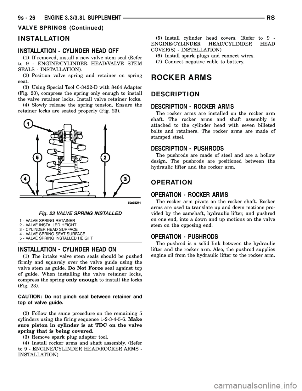
(4) Slowly release the spring tension. Ensure the
retainer locks are seated properly (Fig. 23).
INSTALLATION - CYLINDER HEAD ON
(1) The intake valve stem seals should be pushed
firmly and squarely over the valve guide using the
valve stem as guide.Do Not Forceseal against top
of guide. When installing the valve retainer locks,
compress the springonly enoughto install the locks
(Fig. 23).
CAUTION: Do not pinch seal between retainer and
top of valve guide.
(2) Follow the same procedure on the remaining 5
cylinders using the firing sequence 1-2-3-4-5-6.Make
sure piston in cylinder is at TDC on the valve
spring that is being covered.
(3) Remove spark plug adapter tool.
(4) Install rocker arms and shaft assembly. (Refer
to 9 - ENGINE/CYLINDER HEAD/ROCKER ARMS -
INSTALLATION)(5) Install cylinder head covers. (Refer to 9 -
ENGINE/CYLINDER HEAD/CYLINDER HEAD
COVER(S) - INSTALLATION)
(6) Install spark plugs and connect wires.
(7) Connect negative cable to battery.
ROCKER ARMS
DESCRIPTION
DESCRIPTION - ROCKER ARMS
The rocker arms are installed on the rocker arm
shaft. The rocker arms and shaft assembly is
attached to the cylinder head with seven billeted
bolts and retainers. The rocker arms are made of
stamped steel.
DESCRIPTION - PUSHRODS
The pushrods are made of steel and are a hollow
design. The pushrods are positioned between the
hydraulic lifter and the rocker arm.
OPERATION
OPERATION - ROCKER ARMS
The rocker arm pivots on the rocker shaft. Rocker
arms are used to translate up and down motions pro-
vided by the camshaft, hydraulic lifter, and pushrod
on one end, into a down and up motions on the valve
stem on the opposing end.
OPERATION - PUSHRODS
The pushrod is a solid link between the hydraulic
lifter and the rocker arm. Also, the pushrod supplies
engine oil from the hydraulic lifter to the rocker arm.
Fig. 23 VALVE SPRING INSTALLED
1 - VALVE SPRING RETAINER
2 - VALVE INSTALLED HEIGHT
3 - CYLINDER HEAD SURFACE
4 - VALVE SPRING SEAT SURFACE
5 - VALVE SPRING INSTALLED HEIGHT
9s - 26 ENGINE 3.3/3.8L SUPPLEMENTRS
VALVE SPRINGS (Continued)
Page 1482 of 2585
REMOVAL - ROCKER ARMS AND SHAFT
(1) Remove the cylinder head cover(s). (Refer to 9 -
ENGINE/CYLINDER HEAD/CYLINDER HEAD
COVER(S) - REMOVAL)
NOTE: Rocker arm shaft bolts are captured to the
shaft.
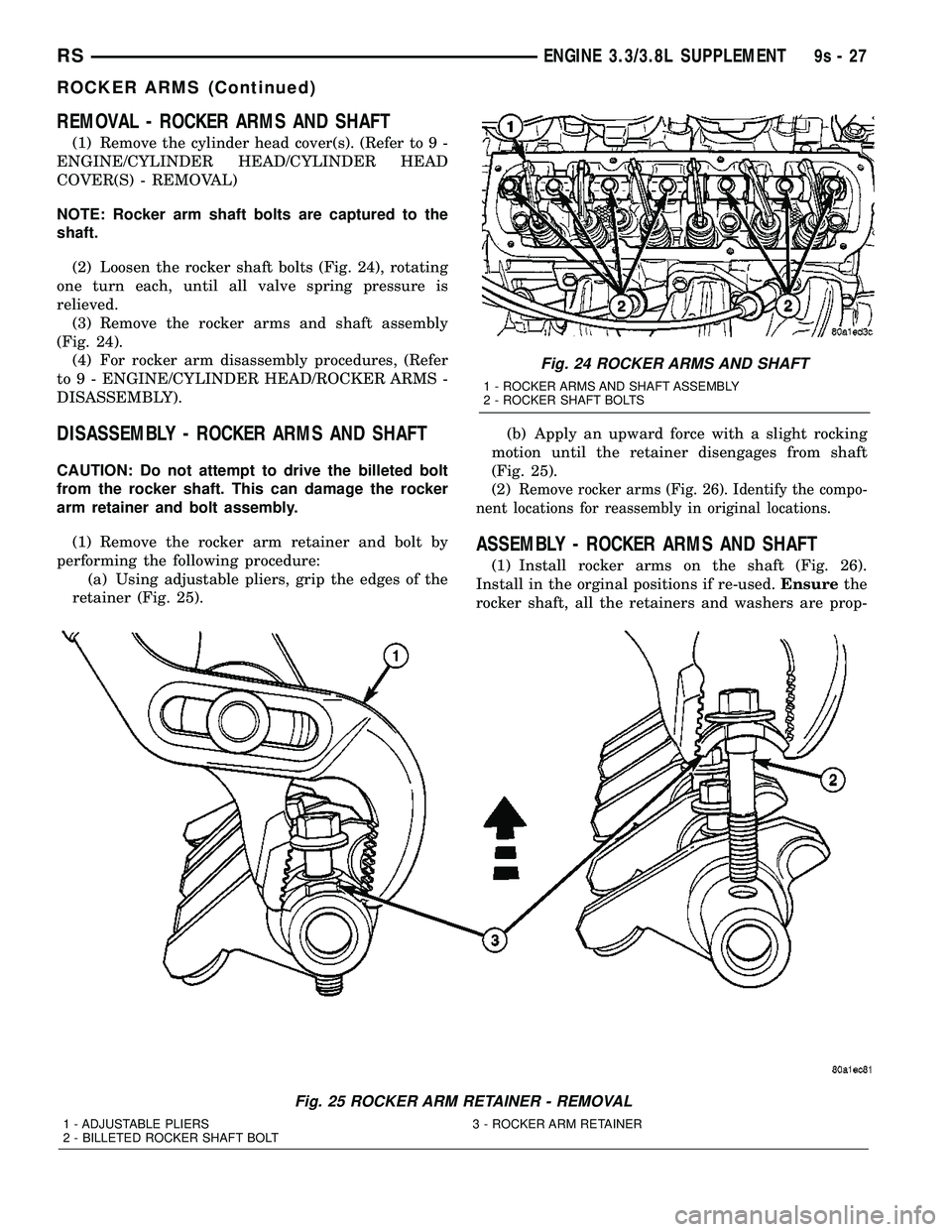
(2) Loosen the rocker shaft bolts (Fig. 24), rotating
one turn each, until all valve spring pressure is
relieved.
(3) Remove the rocker arms and shaft assembly
(Fig. 24).
(4) For rocker arm disassembly procedures, (Refer
to 9 - ENGINE/CYLINDER HEAD/ROCKER ARMS -
DISASSEMBLY).
DISASSEMBLY - ROCKER ARMS AND SHAFT
CAUTION: Do not attempt to drive the billeted bolt
from the rocker shaft. This can damage the rocker
arm retainer and bolt assembly.
(1) Remove the rocker arm retainer and bolt by
performing the following procedure:
(a) Using adjustable pliers, grip the edges of the
retainer (Fig. 25).(b) Apply an upward force with a slight rocking
motion until the retainer disengages from shaft
(Fig. 25).
(2)
Remove rocker arms (Fig. 26). Identify the compo-
nent locations for reassembly in original locations.
ASSEMBLY - ROCKER ARMS AND SHAFT
(1) Install rocker arms on the shaft (Fig. 26).
Install in the orginal positions if re-used.Ensurethe
rocker shaft, all the retainers and washers are prop-
Fig. 24 ROCKER ARMS AND SHAFT
1 - ROCKER ARMS AND SHAFT ASSEMBLY
2 - ROCKER SHAFT BOLTS
Fig. 25 ROCKER ARM RETAINER - REMOVAL
1 - ADJUSTABLE PLIERS 3 - ROCKER ARM RETAINER
2 - BILLETED ROCKER SHAFT BOLT
RSENGINE 3.3/3.8L SUPPLEMENT9s-27
ROCKER ARMS (Continued)
Page 1483 of 2585

erly positioned and installed in the correct locations
(Fig. 26).
(2) Install rocker arms and shaft to the cylinder
head. (Refer to 9 - ENGINE/CYLINDER HEAD/
ROCKER ARMS - INSTALLATION)
INSTALLATION - ROCKER ARMS AND SHAFT
CAUTION: Ensure the longer shaft retaining bolt is
installed in the proper location on the rocker shaft.
(Refer to 9 - ENGINE/CYLINDER HEAD/ROCKER
ARMS - ASSEMBLY)
(1) Position the rocker arm and shaft assemblies
on the pedestal mounts.
CAUTION: Ensure all pushrods are properly located
on the lifter and the rocker arm socket.
(2) Align each rocker arm socket with each push-
rod end.
CAUTION: The rocker arm shaft should be tight-
ened down slowly, starting with the center bolts.
Allow 20 minutes lifter bleed down time after instal-
lation of the rocker shafts before engine operation.(3) Slowly tighten rocker shaft bolts evenly until
shaft is seated. Tighten bolts to 23 N´m (200 in. lbs.)
(Fig. 27).
(4) Install the cylinder head cover(s). (Refer to 9 -
ENGINE/CYLINDER HEAD/CYLINDER HEAD
COVER(S) - INSTALLATION)
Fig. 26 ROCKER ARMS AND SHAFT
1 - BOLT (ROCKER SHAFT OIL FEED - LONGER LENGTH) 5 - ROCKER ARM - EXHAUST
2 - SHAFT RETAINER/SPACER - 21.5 mm (0.84 in.) 6 - WASHER
3 -SHAFT RETAINER/SPACER - 37.5 mm (1.47 in.) 7 - ROCKER ARM - INTAKE (LARGER OFFSET)
4 - SHAFT RETAINER/SPACER - 40.9 mm (1.61 in.) 8 - ROCKER ARMS LUBRICATION FEED HOLE (POSITION
UPWARD & TOWARD VALVE SPRING)
Fig. 27 ROCKER ARMS AND SHAFT
1 - ROCKER ARMS AND SHAFT ASSEMBLY
2 - ROCKER SHAFT BOLTS
9s - 28 ENGINE 3.3/3.8L SUPPLEMENTRS
ROCKER ARMS (Continued)
Page 1484 of 2585
VALVE STEM SEALS
DESCRIPTION
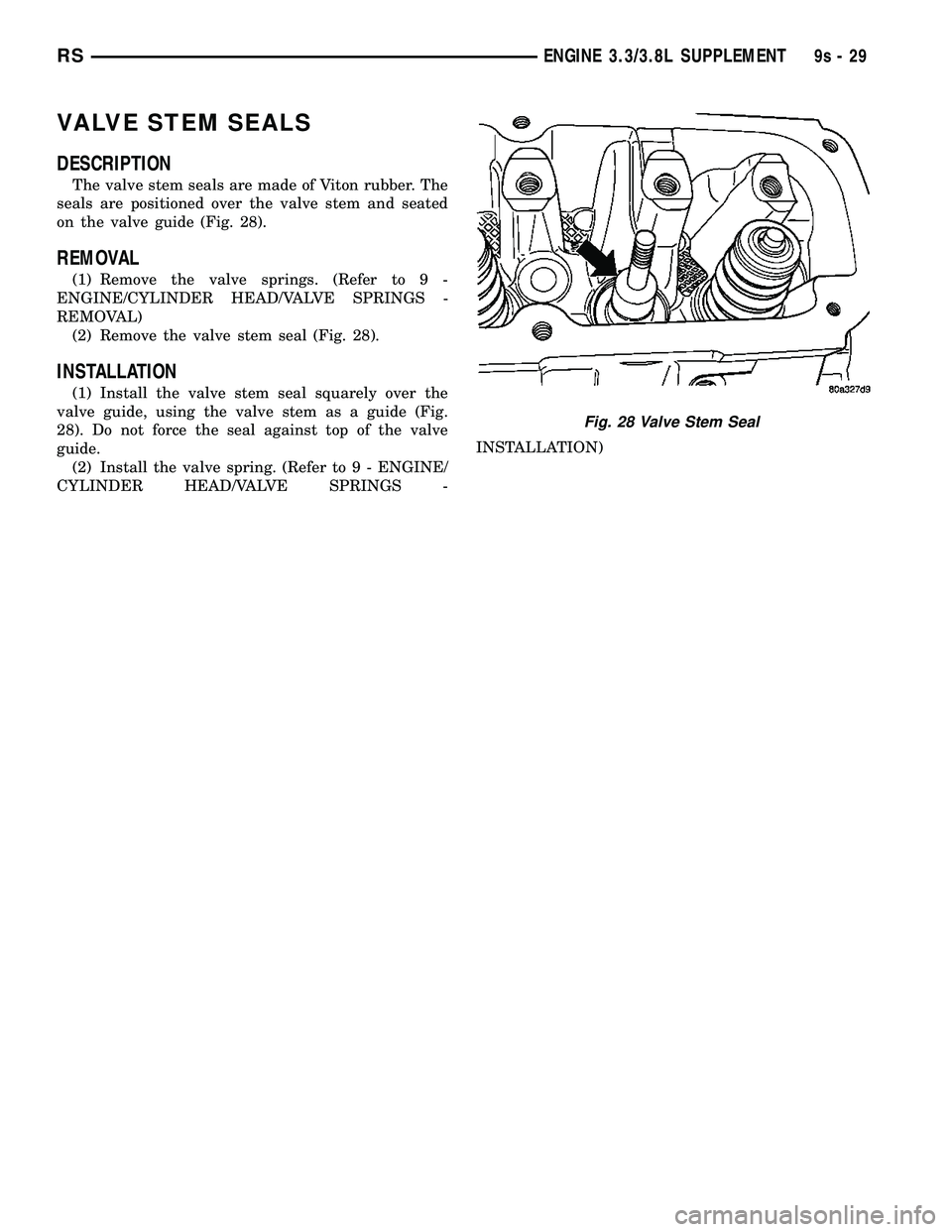
The valve stem seals are made of Viton rubber. The
seals are positioned over the valve stem and seated
on the valve guide (Fig. 28).
REMOVAL
(1) Remove the valve springs. (Refer to 9 -
ENGINE/CYLINDER HEAD/VALVE SPRINGS -
REMOVAL)
(2) Remove the valve stem seal (Fig. 28).
INSTALLATION
(1) Install the valve stem seal squarely over the
valve guide, using the valve stem as a guide (Fig.
28). Do not force the seal against top of the valve
guide.
(2) Install the valve spring. (Refer to 9 - ENGINE/
CYLINDER HEAD/VALVE SPRINGS -INSTALLATION)
Fig. 28 Valve Stem Seal
RSENGINE 3.3/3.8L SUPPLEMENT9s-29
Page 1486 of 2585
EXHAUST SYSTEM
TABLE OF CONTENTS
page page
EXHAUST SYSTEM
DESCRIPTION..........................1
DIAGNOSIS AND TESTING
DIAGNOSIS AND TESTING - EXCESSIVE
EXHAUST SYSTEM NOISE...............2
DIAGNOSIS AND TESTING - EXHAUST
SYSTEM RESTRICTION CHECK...........2
INSPECTION...........................3
ADJUSTMENTS.........................3
SPECIFICATIONS
TORQUE.............................3
SPECIAL TOOLS
EXHAUST SYSTEM.....................4
CATALYTIC CONVERTER
DESCRIPTION..........................4
OPERATION............................4
REMOVAL.............................5INSPECTION...........................5
INSTALLATION..........................6
CROSS-OVER PIPE - 3.3/3.8L
REMOVAL.............................6
INSTALLATION..........................6
HEAT SHIELDS
DESCRIPTION..........................6
OPERATION............................7
REMOVAL.............................7
INSTALLATION..........................7
MUFFLER
REMOVAL.............................7
INSTALLATION..........................7
RESONATOR
REMOVAL.............................9
INSTALLATION..........................9
EXHAUST SYSTEM
DESCRIPTION
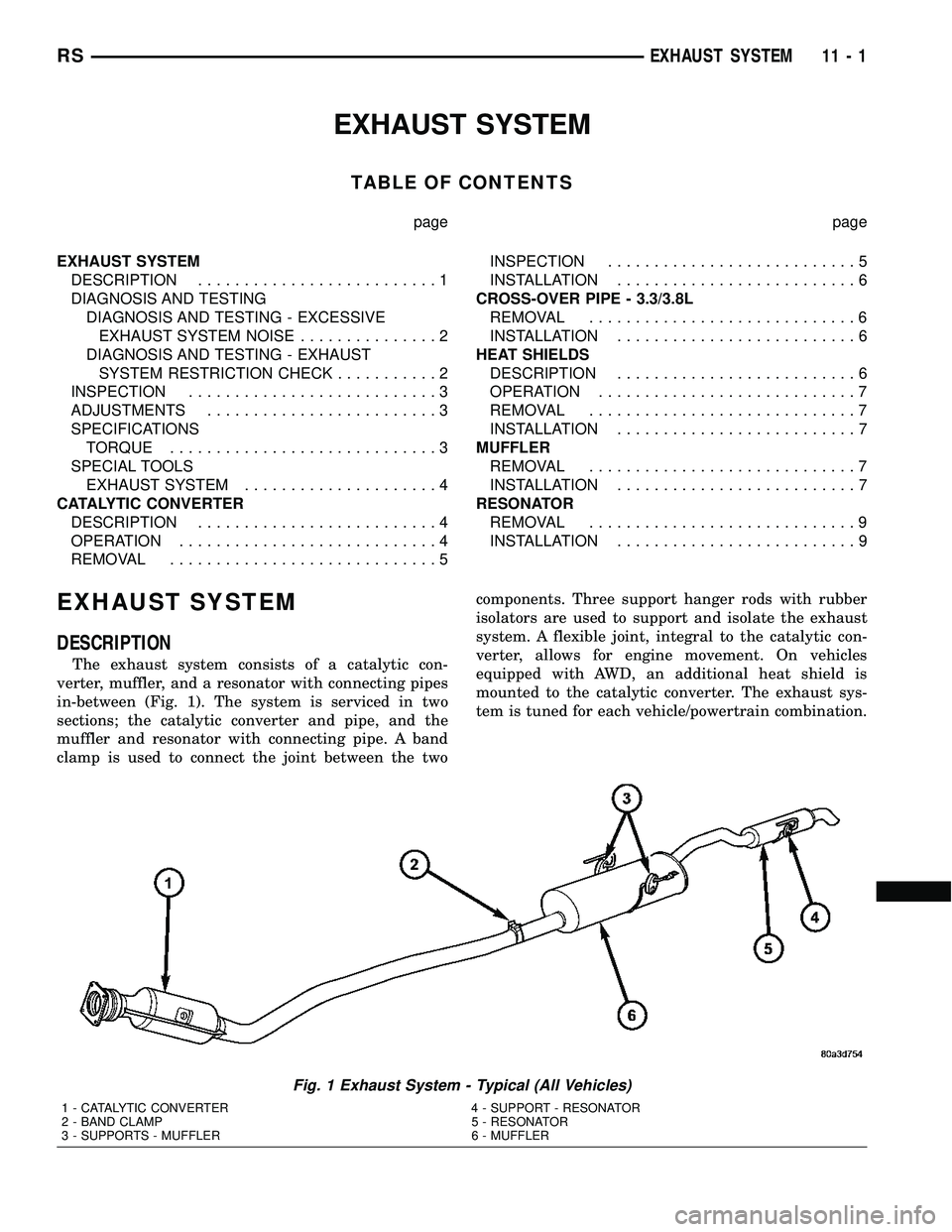
The exhaust system consists of a catalytic con-
verter, muffler, and a resonator with connecting pipes
in-between (Fig. 1). The system is serviced in two
sections; the catalytic converter and pipe, and the
muffler and resonator with connecting pipe. A band
clamp is used to connect the joint between the twocomponents. Three support hanger rods with rubber
isolators are used to support and isolate the exhaust
system. A flexible joint, integral to the catalytic con-
verter, allows for engine movement. On vehicles
equipped with AWD, an additional heat shield is
mounted to the catalytic converter. The exhaust sys-
tem is tuned for each vehicle/powertrain combination.
Fig. 1 Exhaust System - Typical (All Vehicles)
1 - CATALYTIC CONVERTER 4 - SUPPORT - RESONATOR
2 - BAND CLAMP 5 - RESONATOR
3 - SUPPORTS - MUFFLER 6 - MUFFLER
RSEXHAUST SYSTEM11-1
Page 1487 of 2585
DIAGNOSIS AND TESTING
DIAGNOSIS AND TESTING - EXCESSIVE
EXHAUST SYSTEM NOISE
CONDITION POSSIBLE CAUSES CORRECTION
EXCESSIVE EXHAUST NOISE
(UNDER HOOD)1. Exhaust manifold cracked or
broken.1. Replace manifold.
2. Manifold to cylinder head leak. 2. Tighten manifold and/or replace
gasket.
3. EGR Valve to manifold gasket
leakage.3. Tighten fasteners or replace
gasket.
4. EGR Valve to EGR tube gasket
leakage.4. Tighten fasteners or replace
gasket.
5. EGR tube to manifold tube
leakage.5. Tighten tube nut.
6. Exhaust flex-joint to manifold
leak.6. Tighten joint fasteners and/or
replace gasket.
7. Exhaust flex-joint. 7. Replace catalytic converter
assembly.
8. Pipe and shell noise from front
exhaust pipe.8. Characteristic of single wall pipe.
EXCESSIVE EXHAUST NOISE 1. Leak at exhaust pipe joints. 1. Tighten clamps at leaking joints.
2. Burned or rusted out muffler
assembly or exhaust pipe.2. Replace muffler resonator tailpipe
assembly or exhaust pipe with
catalytic converter assembly.
3. Burned or rusted out resonator. 3. Replace muffler resonator tailpipe
assembly.
4. Restriction in exhaust system. 4. Perform Exhaust System
Restriction Check. Replace
component as necessary.
5. Converter material in muffler. 5. Replace muffler and converter
assemblies. Check fuel injection and
ignition systems for proper
operation.
DIAGNOSIS AND TESTING - EXHAUST SYSTEM
RESTRICTION CHECK
Exhaust system restriction can be checked by mea-
suring back pressure using the DRB IIItand PEP
module pressure tester.
WARNING: THE NORMAL OPERATING TEMPERA-
TURE OF THE EXHAUST SYSTEM IS VERY HIGH.
THEREFORE, NEVER WORK AROUND OR ATTEMPT
TO SERVICE ANY PART OF THE EXHAUST SYSTEM
UNTIL IT IS COOLED. SPECIAL CARE SHOULD BE
TAKEN WHEN WORKING NEAR THE CATALYTIC
CONVERTER. THE TEMPERATURE OF THE CON-VERTER RISES TO A HIGH LEVEL AFTER A SHORT
PERIOD OF ENGINE OPERATION TIME.
NOTE: For Special Tool identification, (Refer to 11 -
EXHAUST SYSTEM - SPECIAL TOOLS).
(1) Disconnect and remove the upstream (before
catalytic converter) oxygen sensor. (Refer to 14 -
FUEL SYSTEM/FUEL INJECTION/O2 SENSOR -
REMOVAL)
(2) Install the Exhaust Back Pressure Fitting
Adaptor CH8519.
(3) Connect the Low Pressure Sensor (15 psi)
CH7063 to the back pressure fitting.
11 - 2 EXHAUST SYSTEMRS
EXHAUST SYSTEM (Continued)