2004 CHRYSLER VOYAGER engine
[x] Cancel search: enginePage 1454 of 2585
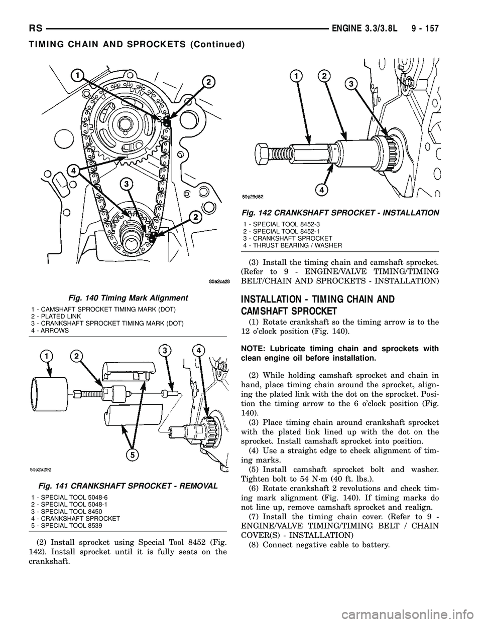
(2) Install sprocket using Special Tool 8452 (Fig.
142). Install sprocket until it is fully seats on the
crankshaft.(3) Install the timing chain and camshaft sprocket.
(Refer to 9 - ENGINE/VALVE TIMING/TIMING
BELT/CHAIN AND SPROCKETS - INSTALLATION)
INSTALLATION - TIMING CHAIN AND
CAMSHAFT SPROCKET
(1) Rotate crankshaft so the timing arrow is to the
12 o'clock position (Fig. 140).
NOTE: Lubricate timing chain and sprockets with
clean engine oil before installation.
(2) While holding camshaft sprocket and chain in
hand, place timing chain around the sprocket, align-
ing the plated link with the dot on the sprocket. Posi-
tion the timing arrow to the 6 o'clock position (Fig.
140).
(3) Place timing chain around crankshaft sprocket
with the plated link lined up with the dot on the
sprocket. Install camshaft sprocket into position.
(4) Use a straight edge to check alignment of tim-
ing marks.
(5) Install camshaft sprocket bolt and washer.
Tighten bolt to 54 N´m (40 ft. lbs.).
(6) Rotate crankshaft 2 revolutions and check tim-
ing mark alignment (Fig. 140). If timing marks do
not line up, remove camshaft sprocket and realign.
(7) Install the timing chain cover. (Refer to 9 -
ENGINE/VALVE TIMING/TIMING BELT / CHAIN
COVER(S) - INSTALLATION)
(8) Connect negative cable to battery.
Fig. 140 Timing Mark Alignment
1 - CAMSHAFT SPROCKET TIMING MARK (DOT)
2 - PLATED LINK
3 - CRANKSHAFT SPROCKET TIMING MARK (DOT)
4 - ARROWS
Fig. 141 CRANKSHAFT SPROCKET - REMOVAL
1 - SPECIAL TOOL 5048-6
2 - SPECIAL TOOL 5048-1
3 - SPECIAL TOOL 8450
4 - CRANKSHAFT SPROCKET
5 - SPECIAL TOOL 8539
Fig. 142 CRANKSHAFT SPROCKET - INSTALLATION
1 - SPECIAL TOOL 8452-3
2 - SPECIAL TOOL 8452-1
3 - CRANKSHAFT SPROCKET
4 - THRUST BEARING / WASHER
RSENGINE 3.3/3.8L9 - 157
TIMING CHAIN AND SPROCKETS (Continued)
Page 1456 of 2585

ENGINE
TABLE OF CONTENTS
page page
ENGINE 2.4L SUPPLEMENT.................. 1ENGINE 3.3/3.8L SUPPLEMENT............. 10
ENGINE 2.4L SUPPLEMENT
TABLE OF CONTENTS
page page
ENGINE 2.4L SUPPLEMENT
SPECIFICATIONS - 2.4L ENGINE............1
CRANKSHAFT
STANDARD PROCEDURE - CRANKSHAFT
ENDPLAY ............................6REMOVAL - CRANKSHAFT.................6
INSPECTION...........................7
INSTALLATION - CRANKSHAFT.............7
ENGINE 2.4L SUPPLEMENT
SPECIFICATIONS - 2.4L ENGINE
GENERAL SPECIFICATIONS
DESCRIPTION SPECIFICATION
Type In-Line OHV, DOHC
Number of
Cylinders4
Firing Order 1-3-4-2
Compression
Ratio9.5:1
Max. Variation
Between
Cylinders25%
Metric Standard
Displacement 2.4 Liters 148 cu. in.
Bore 87.5 mm 3.445 in.
Stroke 101.0 mm 3.976 in.
Compression
Pressure1172-1551 kPa 170-225 psi
CYLINDER BLOCK
DESCRIPTION SPECIFICATIONS
Metric Standard
Cylinder Bore
Diameter87.4924 -
87.5076 mm3.4446 - 3.4452
in.
Out-of-Round
(Max.)0.051 mm 0.002 in.
Taper (Max.) 0.051 mm 0.002 in.
RSENGINE9s-1
Page 1457 of 2585
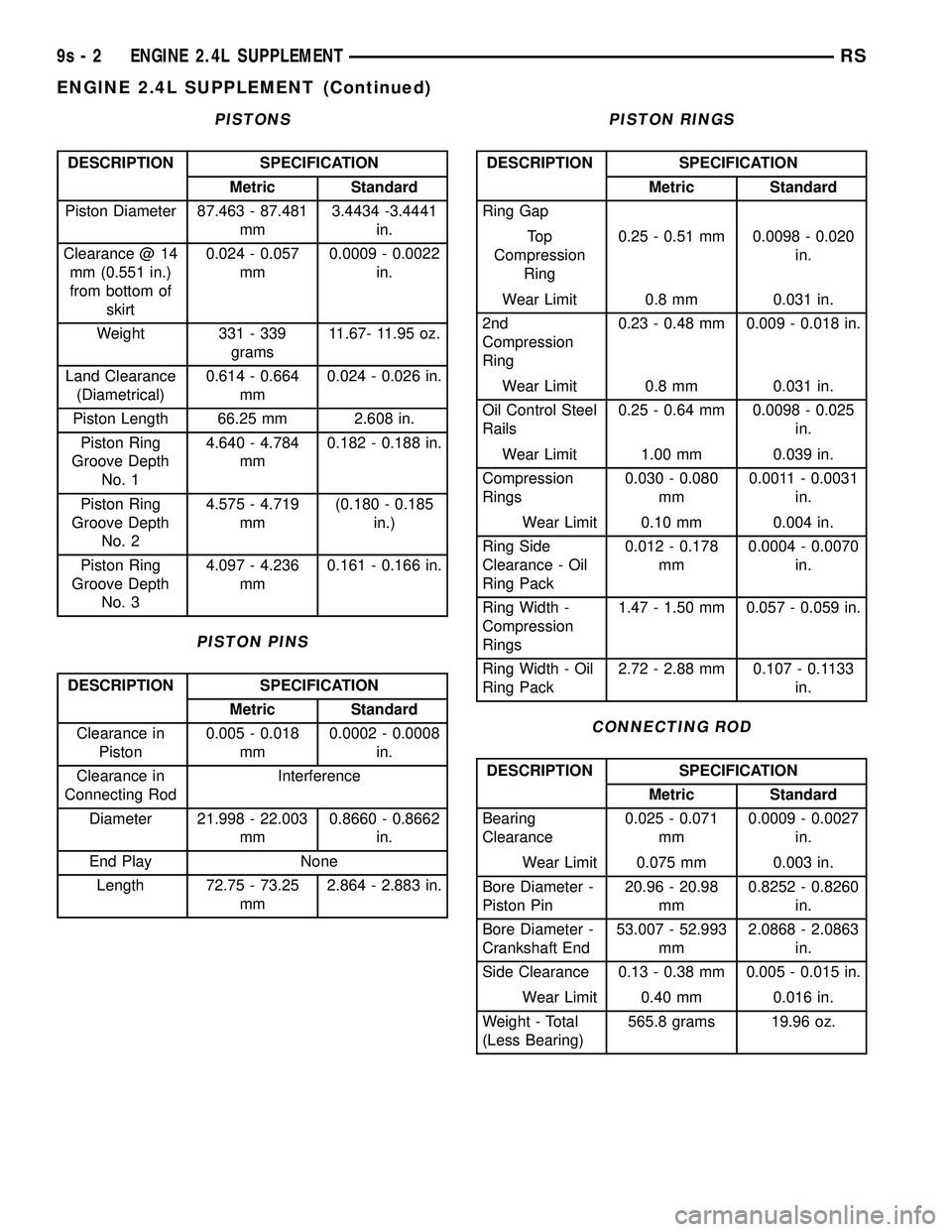
PISTONS
DESCRIPTION SPECIFICATION
Metric Standard
Piston Diameter 87.463 - 87.481
mm3.4434 -3.4441
in.
Clearance @ 14
mm (0.551 in.)
from bottom of
skirt0.024 - 0.057
mm0.0009 - 0.0022
in.
Weight 331 - 339
grams11.67- 11.95 oz.
Land Clearance
(Diametrical)0.614 - 0.664
mm0.024 - 0.026 in.
Piston Length 66.25 mm 2.608 in.
Piston Ring
Groove Depth
No. 14.640 - 4.784
mm0.182 - 0.188 in.
Piston Ring
Groove Depth
No. 24.575 - 4.719
mm(0.180 - 0.185
in.)
Piston Ring
Groove Depth
No. 34.097 - 4.236
mm0.161 - 0.166 in.
PISTON PINS
DESCRIPTION SPECIFICATION
Metric Standard
Clearance in
Piston0.005 - 0.018
mm0.0002 - 0.0008
in.
Clearance in
Connecting RodInterference
Diameter 21.998 - 22.003
mm0.8660 - 0.8662
in.
End Play None
Length 72.75 - 73.25
mm2.864 - 2.883 in.
PISTON RINGS
DESCRIPTION SPECIFICATION
Metric Standard
Ring Gap
To p
Compression
Ring0.25 - 0.51 mm 0.0098 - 0.020
in.
Wear Limit 0.8 mm 0.031 in.
2nd
Compression
Ring0.23 - 0.48 mm 0.009 - 0.018 in.
Wear Limit 0.8 mm 0.031 in.
Oil Control Steel
Rails0.25 - 0.64 mm 0.0098 - 0.025
in.
Wear Limit 1.00 mm 0.039 in.
Compression
Rings0.030 - 0.080
mm0.0011 - 0.0031
in.
Wear Limit 0.10 mm 0.004 in.
Ring Side
Clearance - Oil
Ring Pack0.012 - 0.178
mm0.0004 - 0.0070
in.
Ring Width -
Compression
Rings1.47 - 1.50 mm 0.057 - 0.059 in.
Ring Width - Oil
Ring Pack2.72 - 2.88 mm 0.107 - 0.1133
in.
CONNECTING ROD
DESCRIPTION SPECIFICATION
Metric Standard
Bearing
Clearance0.025 - 0.071
mm0.0009 - 0.0027
in.
Wear Limit 0.075 mm 0.003 in.
Bore Diameter -
Piston Pin20.96 - 20.98
mm0.8252 - 0.8260
in.
Bore Diameter -
Crankshaft End53.007 - 52.993
mm2.0868 - 2.0863
in.
Side Clearance 0.13 - 0.38 mm 0.005 - 0.015 in.
Wear Limit 0.40 mm 0.016 in.
Weight - Total
(Less Bearing)565.8 grams 19.96 oz.
9s - 2 ENGINE 2.4L SUPPLEMENTRS
ENGINE 2.4L SUPPLEMENT (Continued)
Page 1458 of 2585
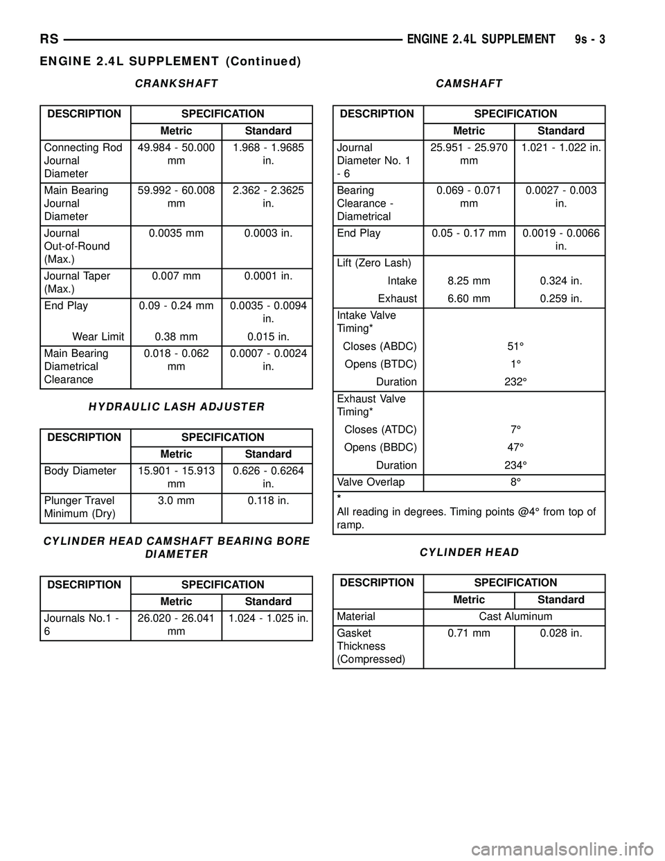
CRANKSHAFT
DESCRIPTION SPECIFICATION
Metric Standard
Connecting Rod
Journal
Diameter49.984 - 50.000
mm1.968 - 1.9685
in.
Main Bearing
Journal
Diameter59.992 - 60.008
mm2.362 - 2.3625
in.
Journal
Out-of-Round
(Max.)0.0035 mm 0.0003 in.
Journal Taper
(Max.)0.007 mm 0.0001 in.
End Play 0.09 - 0.24 mm 0.0035 - 0.0094
in.
Wear Limit 0.38 mm 0.015 in.
Main Bearing
Diametrical
Clearance0.018 - 0.062
mm0.0007 - 0.0024
in.
HYDRAULIC LASH ADJUSTER
DESCRIPTION SPECIFICATION
Metric Standard
Body Diameter 15.901 - 15.913
mm0.626 - 0.6264
in.
Plunger Travel
Minimum (Dry)3.0 mm 0.118 in.
CYLINDER HEAD CAMSHAFT BEARING BORE
DIAMETER
DSECRIPTION SPECIFICATION
Metric Standard
Journals No.1 -
626.020 - 26.041
mm1.024 - 1.025 in.
CAMSHAFT
DESCRIPTION SPECIFICATION
Metric Standard
Journal
Diameter No. 1
-625.951 - 25.970
mm1.021 - 1.022 in.
Bearing
Clearance -
Diametrical0.069 - 0.071
mm0.0027 - 0.003
in.
End Play 0.05 - 0.17 mm 0.0019 - 0.0066
in.
Lift (Zero Lash)
Intake 8.25 mm 0.324 in.
Exhaust 6.60 mm 0.259 in.
Intake Valve
Timing*
Closes (ABDC) 51É
Opens (BTDC) 1É
Duration 232É
Exhaust Valve
Timing*
Closes (ATDC) 7É
Opens (BBDC) 47É
Duration 234É
Valve Overlap 8É
*
All reading in degrees. Timing points @4É from top of
ramp.
CYLINDER HEAD
DESCRIPTION SPECIFICATION
Metric Standard
Material Cast Aluminum
Gasket
Thickness
(Compressed)0.71 mm 0.028 in.
RSENGINE 2.4L SUPPLEMENT9s-3
ENGINE 2.4L SUPPLEMENT (Continued)
Page 1459 of 2585
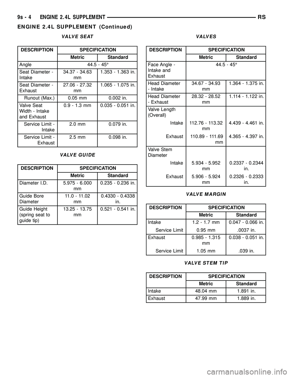
VALVE SEAT
DESCRIPTION SPECIFICATION
Metric Standard
Angle 44.5 - 45É
Seat Diameter -
Intake34.37 - 34.63
mm1.353 - 1.363 in.
Seat Diameter -
Exhaust27.06 - 27.32
mm1.065 - 1.075 in.
Runout (Max.) 0.05 mm 0.002 in.
Valve Seat
Width - Intake
and Exhaust0.9 - 1.3 mm 0.035 - 0.051 in.
Service Limit -
Intake2.0 mm 0.079 in.
Service Limit -
Exhaust2.5 mm 0.098 in.
VALVE GUIDE
DESCRIPTION SPECIFICATION
Metric Standard
Diameter I.D. 5.975 - 6.000
mm0.235 - 0.236 in.
Guide Bore
Diameter11.0 - 11.02
mm0.4330 - 0.4338
in.
Guide Height
(spring seat to
guide tip)13.25 - 13.75
mm0.521 - 0.541 in.
VALVES
DESCRIPTION SPECIFICATION
Metric Standard
Face Angle -
Intake and
Exhaust44.5 - 45É
Head Diameter
- Intake34.67 - 34.93
mm1.364 - 1.375 in.
Head Diameter
- Exhaust28.32 - 28.52
mm1.114 - 1.122 in.
Valve Length
(Overall)
Intake 112.76 - 113.32
mm4.439 - 4.461 in.
Exhaust 110.89 - 111.69
mm4.365 - 4.397 in.
Valve Stem
Diameter
Intake 5.934 - 5.952
mm0.2337 - 0.2344
in.
Exhaust 5.906 - 5.924
mm0.2326 - 0.2333
in.
VALVE MARGIN
DESCRIPTION SPECIFICATION
Metric Standard
Intake 1.2 - 1.7 mm 0.047 - 0.066 in.
Service Limit 0.95 mm .0037 in.
Exhaust 0.985 - 1.315
mm0.038 - 0.051 in.
Service Limit 1.05 mm .039 in.
VALVE STEM TIP
DESCRIPTION SPECIFICATION
Metric Standard
Intake 48.04 mm 1.891 in.
Exhaust 47.99 mm 1.889 in.
9s - 4 ENGINE 2.4L SUPPLEMENTRS
ENGINE 2.4L SUPPLEMENT (Continued)
Page 1460 of 2585
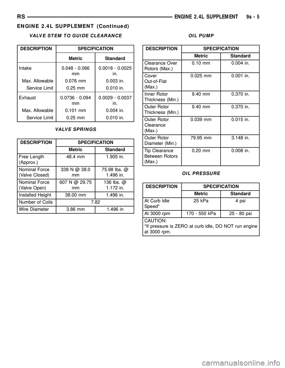
VALVE STEM TO GUIDE CLEARANCE
DESCRIPTION SPECIFICATION
Metric Standard
Intake 0.048 - 0.066
mm0.0018 - 0.0025
in.
Max. Allowable 0.076 mm 0.003 in.
Service Limit 0.25 mm 0.010 in.
Exhaust 0.0736 - 0.094
mm0.0029 - 0.0037
in.
Max. Allowable 0.101 mm 0.004 in.
Service Limit 0.25 mm 0.010 in.
VALVE SPRINGS
DESCRIPTION SPECIFICATION
Metric Standard
Free Length
(Approx.)48.4 mm 1.905 in.
Nominal Force
(Valve Closed)338 N @ 38.0
mm75.98 lbs. @
1.496 in.
Nominal Force
(Valve Open)607 N @ 29.75
mm136 lbs. @
1.172 in.
Installed Height 38.00 mm 1.496 in.
Number of Coils 7.82
Wire Diameter 3.86 mm 1.496 in
OIL PUMP
DESCRIPTION SPECIFICATION
Metric Standard
Clearance Over
Rotors (Max.)0.10 mm 0.004 in.
Cover
Out-of-Flat
(Max.)0.025 mm 0.001 in.
Inner Rotor
Thickness (Min.)9.40 mm 0.370 in.
Outer Rotor
Thickness (Min.)9.40 mm 0.370 in.
Outer Rotor
Clearance
(Max.)0.039 mm 0.015 in.
Outer Rotor
Diameter (Min.)79.95 mm 3.148 in.
Tip Clearance
Between Rotors
(Max.)0.20 mm 0.008 in.
OIL PRESSURE
DESCRIPTION SPECIFICATION
Metric Standard
At Curb Idle
Speed*25 kPa 4 psi
At 3000 rpm 170 - 550 kPa 25 - 80 psi
CAUTION:
*If pressure is ZERO at curb idle, DO NOT run engine
at 3000 rpm.
RSENGINE 2.4L SUPPLEMENT9s-5
ENGINE 2.4L SUPPLEMENT (Continued)
Page 1461 of 2585
CRANKSHAFT
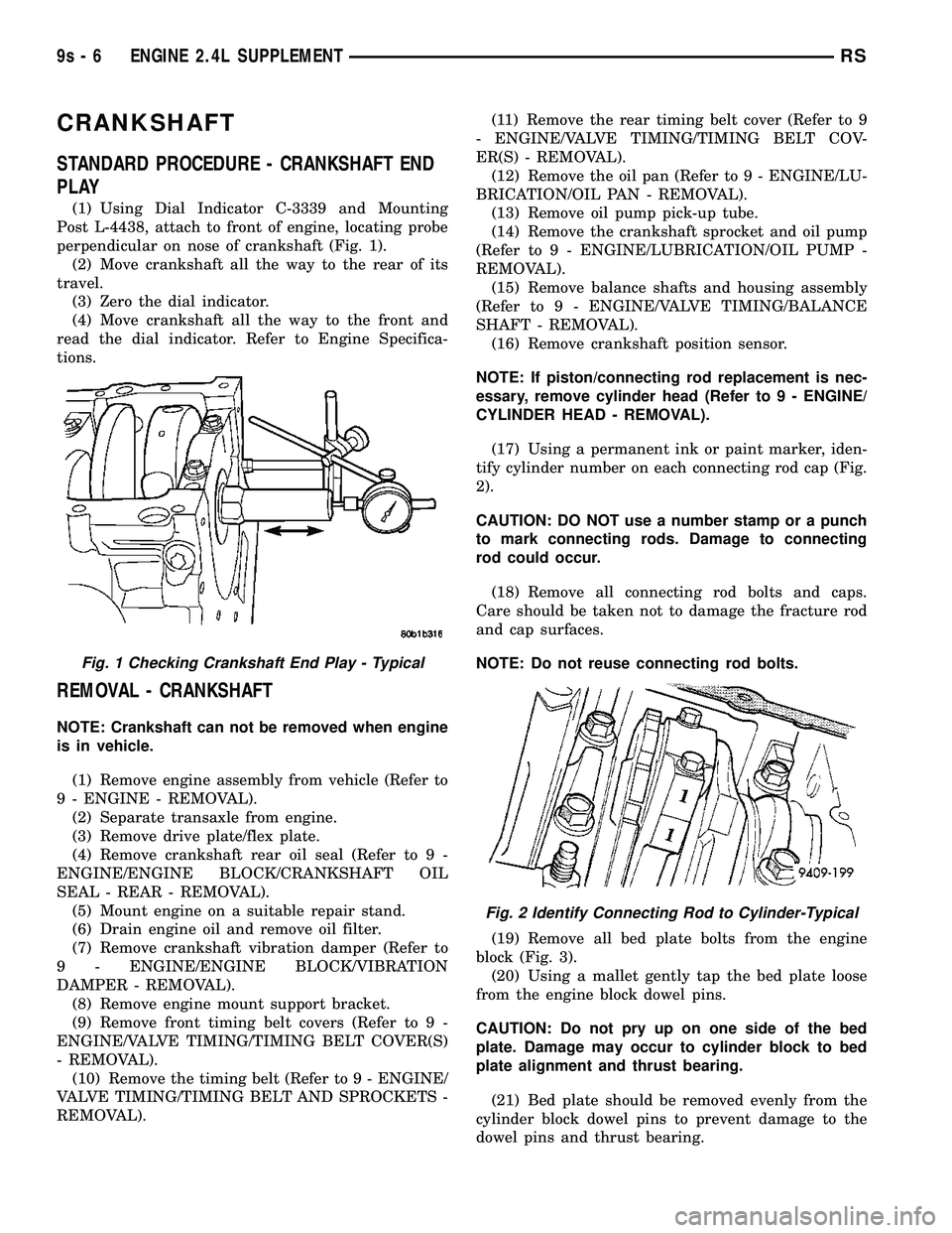
STANDARD PROCEDURE - CRANKSHAFT END
PLAY
(1) Using Dial Indicator C-3339 and Mounting
Post L-4438, attach to front of engine, locating probe
perpendicular on nose of crankshaft (Fig. 1).
(2) Move crankshaft all the way to the rear of its
travel.
(3) Zero the dial indicator.
(4) Move crankshaft all the way to the front and
read the dial indicator. Refer to Engine Specifica-
tions.
REMOVAL - CRANKSHAFT
NOTE: Crankshaft can not be removed when engine
is in vehicle.
(1) Remove engine assembly from vehicle (Refer to
9 - ENGINE - REMOVAL).
(2) Separate transaxle from engine.
(3) Remove drive plate/flex plate.
(4) Remove crankshaft rear oil seal (Refer to 9 -
ENGINE/ENGINE BLOCK/CRANKSHAFT OIL
SEAL - REAR - REMOVAL).
(5) Mount engine on a suitable repair stand.
(6) Drain engine oil and remove oil filter.
(7) Remove crankshaft vibration damper (Refer to
9 - ENGINE/ENGINE BLOCK/VIBRATION
DAMPER - REMOVAL).
(8) Remove engine mount support bracket.
(9) Remove front timing belt covers (Refer to 9 -
ENGINE/VALVE TIMING/TIMING BELT COVER(S)
- REMOVAL).
(10) Remove the timing belt (Refer to 9 - ENGINE/
VALVE TIMING/TIMING BELT AND SPROCKETS -
REMOVAL).(11) Remove the rear timing belt cover (Refer to 9
- ENGINE/VALVE TIMING/TIMING BELT COV-
ER(S) - REMOVAL).
(12) Remove the oil pan (Refer to 9 - ENGINE/LU-
BRICATION/OIL PAN - REMOVAL).
(13) Remove oil pump pick-up tube.
(14) Remove the crankshaft sprocket and oil pump
(Refer to 9 - ENGINE/LUBRICATION/OIL PUMP -
REMOVAL).
(15) Remove balance shafts and housing assembly
(Refer to 9 - ENGINE/VALVE TIMING/BALANCE
SHAFT - REMOVAL).
(16) Remove crankshaft position sensor.
NOTE: If piston/connecting rod replacement is nec-
essary, remove cylinder head (Refer to 9 - ENGINE/
CYLINDER HEAD - REMOVAL).
(17) Using a permanent ink or paint marker, iden-
tify cylinder number on each connecting rod cap (Fig.
2).
CAUTION: DO NOT use a number stamp or a punch
to mark connecting rods. Damage to connecting
rod could occur.
(18) Remove all connecting rod bolts and caps.
Care should be taken not to damage the fracture rod
and cap surfaces.
NOTE: Do not reuse connecting rod bolts.
(19) Remove all bed plate bolts from the engine
block (Fig. 3).
(20) Using a mallet gently tap the bed plate loose
from the engine block dowel pins.
CAUTION: Do not pry up on one side of the bed
plate. Damage may occur to cylinder block to bed
plate alignment and thrust bearing.
(21) Bed plate should be removed evenly from the
cylinder block dowel pins to prevent damage to the
dowel pins and thrust bearing.
Fig. 1 Checking Crankshaft End Play - Typical
Fig. 2 Identify Connecting Rod to Cylinder-Typical
9s - 6 ENGINE 2.4L SUPPLEMENTRS
Page 1462 of 2585
CAUTION: Use extreme care when handling crank-
shaft. Tone wheel damage can occur if crankshaft is
mis-handled.
(22) Lift out crankshaft from cylinder block. Do
not damage the main bearings or journals when
removing the crankshaft.
(23) Remove the target ring mounting screws and
discard.
(24) Remove the target ring from the crankshaft.
INSPECTION
For crankshaft specifications (Refer to 9 - ENGINE
- SPECIFICATIONS).
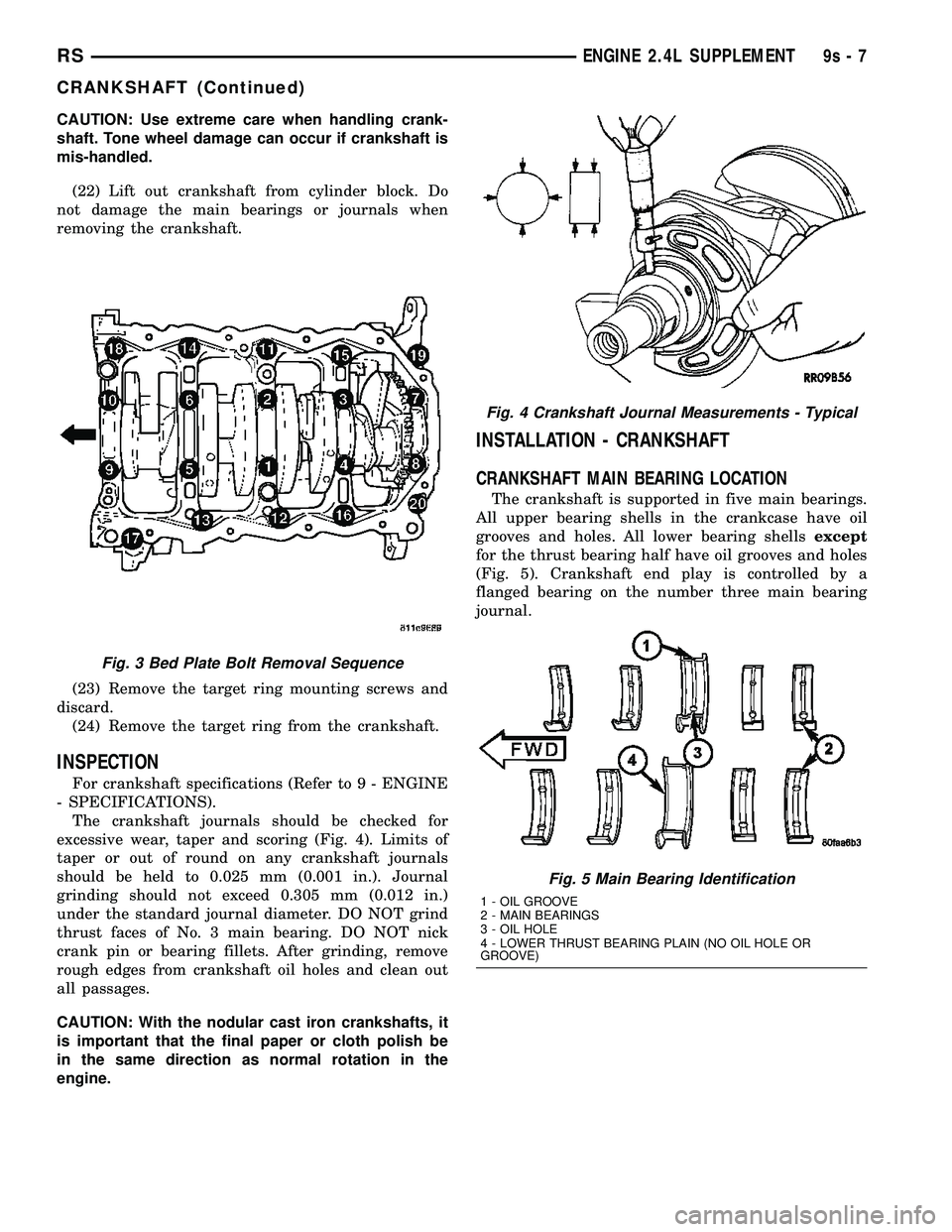
The crankshaft journals should be checked for
excessive wear, taper and scoring (Fig. 4). Limits of
taper or out of round on any crankshaft journals
should be held to 0.025 mm (0.001 in.). Journal
grinding should not exceed 0.305 mm (0.012 in.)
under the standard journal diameter. DO NOT grind
thrust faces of No. 3 main bearing. DO NOT nick
crank pin or bearing fillets. After grinding, remove
rough edges from crankshaft oil holes and clean out
all passages.
CAUTION: With the nodular cast iron crankshafts, it
is important that the final paper or cloth polish be
in the same direction as normal rotation in the
engine.
INSTALLATION - CRANKSHAFT
CRANKSHAFT MAIN BEARING LOCATION
The crankshaft is supported in five main bearings.
All upper bearing shells in the crankcase have oil
grooves and holes. All lower bearing shellsexcept
for the thrust bearing half have oil grooves and holes
(Fig. 5). Crankshaft end play is controlled by a
flanged bearing on the number three main bearing
journal.
Fig. 3 Bed Plate Bolt Removal Sequence
Fig. 4 Crankshaft Journal Measurements - Typical
Fig. 5 Main Bearing Identification
1 - OIL GROOVE
2 - MAIN BEARINGS
3 - OIL HOLE
4 - LOWER THRUST BEARING PLAIN (NO OIL HOLE OR
GROOVE)
RSENGINE 2.4L SUPPLEMENT9s-7
CRANKSHAFT (Continued)