2004 CHRYSLER VOYAGER warning light
[x] Cancel search: warning lightPage 2196 of 2585
BASE COAT/CLEARCOAT
FINISH
DESCRIPTION
On most vehicles a two-part paint application
(basecoat/clearcoat) is used. Color paint that is
applied to primer is called basecoat. The clearcoat
protects the basecoat from ultraviolet light and pro-
vides a durable high-gloss finish.
CAUTION: Do not use abrasive chemicals or com-
pounds on painted surfaces. Damage to finish can
result.
Do not use harsh alkaline based cleaning solvents
on painted surfaces. Damage to finish or color can
result.
PAINT CODE
DESCRIPTION
Exterior vehicle body colors are identified on the
Body Code plate. (Refer to VEHICLE DATA/VEHI-
CLE INFORMATION/BODY CODE PLATE -
DESCRIPTION). The paint code is also identified on
the Vehicle Safety Certification Label which is
located on the drivers door shut face. The first digit
of the paint code listed on the vehicle indicates the
sequence of application, i.e.: P = primary coat, Q =
secondary coat. The codes listed in the Color Code
Chart are used for manufacturing purposes.
PAINTED TOUCH-UP
DESCRIPTION
When a painted metal surface has been scratched
or chipped, it should be touched up as soon as possi-
ble to avoid corrosion. For best results, use Mopart
Scratch Filler/Primer, Touch Up Paints and Clear Top
Coat. (Refer to VEHICLE DATA/VEHICLE INFOR-
MATION/BODY CODE PLATE - DESCRIPTION).
WARNING: USE AN OSHA APPROVED RESPIRATOR
AND SAFETY GLASSES WHEN SPRAYING PAINT
OR SOLVENTS IN A CONFINED AREA. PERSONAL
INJURY CAN RESULT.
TOUCH UP PROCEDURE
(1) Scrape loose paint and corrosion from inside
scratch or chip.
(2) Clean affected area with MopartTar/Road Oil
Remover, and allow to dry.
(3) Fill the inside of the scratch or chip with a coat
of filler/primer. Do not overlap primer onto good sur-
face finish. The applicator brush should be wet
enough to puddle-fill the scratch or chip without run-
ning. Do not stroke brush applicator on body surface.
Allow the filler/primer to dry hard.
(4) Cover the filler/primer with color touch up
paint. Do not overlap touch up color onto the original
color coat around the scratch or chip. Butt the new
color to the original color, if possible. Do not stroke
applicator brush on body surface. Allow touch up
paint to dry hard.
(5) On vehicles without clearcoat, the touch up
color can be lightly finesse sanded (1500 grit) and
polished with rubbing compound.
(6) On vehicles with clearcoat, apply clear top coat
to touch up paint with the same technique as
described in Step 4. Allow clear top coat to dry hard.
If desired, Step 5 can be performed on clear top coat.
WARNING: AVOID PROLONGED SKIN CONTACT
WITH PETROLEUM OR ALCOHOL ± BASED CLEAN-
ING SOLVENTS. PERSONAL INJURY CAN RESULT.
FINESSE SANDING/BUFFING &
POLISHING
DESCRIPTION
Minor acid etching, orange peel, or smudging in
clearcoat or single-stage finishes can be reduced with
light finesse sanding, hand buffing, and polishing.If
the finish has been finesse sanded in the past,
it cannot be repeated. Finesse sanding opera-
tion should be performed by a trained automo-
tive paint technician.
CAUTION: Do not remove clearcoat finish, if
equipped. Basecoat paint must retain clearcoat for
durability.
RSPAINT23-85
Page 2405 of 2585
Condition Possible Causes Correction
The low side pressure is too
low, and the high side
pressure is too high.1. Restricted refrigerant flow
through the refrigerant lines.1. See Liquid Line, Suction Line and Discharge
Line in this group. Inspect the refrigerant lines for
kinks, tight bends or improper routing. Correct
the routing or replace the refrigerant line, if
required.
2. Restricted refrigerant flow
through the A/C expansion
valve.2. See A/C Expansion Valve in this group.
Replace the valve, if required.
3. Restricted refrigerant flow
through the A/C condenser.3. See A/C Condenser in this group. Replace the
restricted condenser, if required.
DIAGNOSIS AND TESTING - HEATER
PERFORMANCE TEST
WARNING: REVIEW SAFETY PRECAUTIONS AND
WARNINGS IN THIS GROUP BEFORE PERFORMING
THIS PROCEDURE (Refer to 24 - HEATING & AIR
CONDITIONING/PLUMBING - WARNING).
Check the coolant level, drive belt tension, radiator
air flow and fan operation. Start engine and allow to
warm up to normal operating temperature.
WARNING: DO NOT REMOVE RADIATOR CAP
WHEN ENGINE IS HOT, PERSONAL INJURY CAN
RESULT.
If vehicle has been run recently, wait 15 minutes
before removing the radiator cap. Place a rag overthe cap and turn it to the first safety stop. Allow
pressure to escape through the overflow tube. When
the system pressure stabilizes, remove the cap com-
pletely.
MAXIMUM HEATER OUTPUT: TEST AND ACTION
Engine coolant is provided to the heater system by
two heater hoses. With the engine idling at normal
operating temperature, set the temperature control
to maximum heat, the mode control to the floor posi-
tion, and the blower in the highest speed position.
Using a test thermometer, check the temperature of
the air being discharged from the floor outlets. Com-
pare the test thermometer reading to the Tempera-
ture Reference chart.
TEMPERATURE REFERENCE
Ambient Temperature Minimum Floor Outlet Temperature
Celsius Fahrenheit Celsius Fahrenheit
15.5É 60É 62.2É 144É
21.1É 70É 63.8É 147É
26.6É 80É 65.5É 150É
32.2É 90É 67.2É 153É
If the floor outlet air temperature is insufficient,
check that the cooling system is operating to specifi-
cations (Refer to 7 - COOLING/ENGINE - DIAGNO-
SIS AND TESTING). Both heater hoses should be
HOT to the touch (the coolant return hose should be
slightly cooler than the supply hose). If the coolant
return hose is much cooler than the supply hose,
locate and repair the engine coolant flow obstruction
in heater system.OBSTRUCTED COOLANT FLOW Possible locations or causes
of obstructed coolant flow are as follows:
²Pinched or kinked heater hoses.
²Improper heater hose routing.
²Plugged heater hoses or supply and return ports
at the cooling system connections.
²Plugged heater core.
If proper coolant flow through the cooling system is
verified, and heater outlet air temperature is insuffi-
cient, a mechanical problem may exist.
24 - 10 HEATING & AIR CONDITIONINGRS
HEATING & AIR CONDITIONING (Continued)
Page 2418 of 2585
BLEND DOOR ACTUATOR
DESCRIPTION
The blend door actuators are reversible, 12-volt
Direct Current (DC), servo motors. Models with the
single zone heater and air conditioner system have a
single blend air door, which is controlled by a single
blend door actuator. Models with the optional dual
zone front heater and air conditioner system have
dual blend air doors, which are controlled by two
blend door actuators. The single zone blend door
actuator is located on the driver's side end of the
HVAC housing, close to the middle of the distribution
housing. In the dual zone system, the same blend
door actuator used for the single zone system
becomes the passenger blend door actuator, and is
mechanically connected to only the passenger side
blend air door. In the dual zone system, a second sep-
arate blend door actuator is also located on the
driver side end of the HVAC housing, close to the
middle of the distribution housing, and is mechani-
cally connected to only the driver's side blend air
door.
The blend door actuators are interchangeable with
each other, as well as with the actuators for the
mode door and the recirculation air door. Each actua-
tor is contained within an identical black molded
plastic housing with an integral wire connector
receptacle. Two integral mounting tabs allow the
actuator to be secured with two screws to the distri-
bution housing. Each actuator also has an identical
output shaft with splines that connects it to the link-
age that drives the proper blend air door. The blend
door actuators do not require mechanical indexing to
the blend door linkage, as they are electronically cal-
ibrated by the heater-A/C control module.
OPERATION
Each blend door actuator is connected to the A/C-
heater control through the vehicle electrical system
by a dedicated two-wire lead and connector from the
HVAC wire harness. The blend door actuator can
move the blend-air door in two directions. When the
A/C-heater control pulls the voltage on one side of
the motor connection high and the other connection
low, the blend-air door will move in one direction.
When the A/C-heater control reverses the polarity of
the voltage to the motor, the blend-air door moves in
the opposite direction. When the A/C-heater control
makes the voltage to both connections high or both
connections low, the blend-air door stops and will not
move. The motor connections also provide a feedback
signal to the A/C-heater control. This feedback signal
allows the A/C-heater control to monitor the opera-
tion and relative positions of the blend door actuator
and the blend-air door. The A/C-heater control learnsthe blend door stop positions during the calibration
procedure and will store a diagnostic trouble code
(DTC) for any problems it detects in the blend door
actuator circuits.
The blend door actuator can be diagnosed using a
DRBIIItscan tool. Refer to Body Diagnostic Proce-
dures for more information. The blend door actuators
cannot be adjusted or repaired and, if damaged or
faulty, they must be replaced.
REMOVAL
WARNING: ON VEHICLES EQUIPPED WITH AIR-
BAGS, DISABLE THE AIRBAG SYSTEM BEFORE
ATTEMPTING ANY STEERING WHEEL, STEERING
COLUMN, OR INSTRUMENT PANEL COMPONENT
DIAGNOSIS OR SERVICE. DISCONNECT AND ISO-
LATE THE BATTERY NEGATIVE (GROUND) CABLE,
THEN WAIT TWO MINUTES FOR THE AIRBAG SYS-
TEM CAPACITOR TO DISCHARGE BEFORE PER-
FORMING FURTHER DIAGNOSIS OR SERVICE. THIS
IS THE ONLY SURE WAY TO DISABLE THE AIRBAG
SYSTEM. FAILURE TO TAKE THE PROPER PRE-
CAUTIONS COULD RESULT IN ACCIDENTAL AIR-
BAG DEPLOYMENT AND POSSIBLE PERSONAL
INJURY.
NOTE: The single zone heating and air conditioning
system is equipped with a single blend door actua-
tor. The dual zone system has two blend door
actuators, one for the driver side blend air door and
one for the passenger side blend air door. The
same service procedures can be used for each of
these actuators.
(1) Disconnect and isolate the battery negative
cable.
(2) Remove the silencer from beneath the driver
side end of the instrument panel. (Refer to 23 -
BODY/INSTRUMENT PANEL/INSTRUMENT
PANEL SILENCER - REMOVAL).
(3) Disconnect the wire harness connector from the
blend door actuator(s) (Fig. 11).
(4) Remove the two screws that secure the blend
door actuator to the distribution housing.
(5) Remove the blend door actuator.
INSTALLATION
(1) Position the blend door actuator onto the distri-
bution housing. If necessary, rotate the actuator
slightly to align the splines on the actuator output
shaft with those in the blend air door linkage.
(2) Install the two screws that secure the blend
door actuator to the housing. Tighten the screws to 2
N´m (17 in. lbs.).
RSCONTROLS - FRONT24-23
Page 2426 of 2585
(5) Remove the mode door actuator from the distri-
bution housing.
INSTALLATION
(1) Position the mode door actuator onto the HVAC
distribution housing. If necessary, rotate the actuator
slightly to align the splines on the actuator output
shaft with those in the mode door linkage.
(2) Install the two screws that secure the mode
door actuator to the distribution housing. Tighten the
screws to 2 N´m (17 in. lbs.).
(3) Connect the wire harness connector to the
mode door actuator.
(4) Install the silencer under the driver side end of
the instrument panel (Refer to 23 - BODY/INSTRU-
MENT PANEL/INSTRUMENT PANEL SILENCER -
INSTALLATION).
(5) Reconnect the negative battery cable.
(6) Perform the A/C-heater control calibration pro-
cedure (Refer to 24 - HEATING & AIR CONDITION-
ING/CONTROLS - FRONT/A/C-HEATER CONTROL
- STANDARD PROCEDURE - HEATER-A/C CON-
TROL CALIBRATION).
POWER MODULE - BLOWER
MOTOR
DESCRIPTION
A blower motor power module is used on this
model when it is equipped with the optional Auto-
matic Temperature Control (ATC) system. Modelsequipped with the standard manual heater-A/C sys-
tem use a blower motor resistor block, instead of the
blower motor power module (Refer to 24 - HEATING
& AIR CONDITIONING/CONTROLS/BLOWER
MOTOR RESISTOR BLOCK - DESCRIPTION).
The blower motor power module is mounted to the
rear of the HVAC housing, directly behind the glove
box opening in the instrument panel. The module
consists of a molded plastic mounting plate with two
integral connector receptacles. Concealed behind the
mounting plate is the power module electronic cir-
cuitry and a large finned, heat sink. The blower
motor power module is accessed for service by remov-
ing the glove box from the instrument panel.
OPERATION
The blower motor power module is connected to the
vehicle electrical system through a dedicated lead
and connector from the instrument panel wire har-
ness. A second connector receptacle receives a wire
lead connector from the blower motor. The blower
motor power module allows the microprocessor-based
Automatic Temperature Control (ATC) heater-A/C
control module to calculate and provide infinitely
variable blower motor speeds based upon either man-
ual blower switch input or the ATC programming
using a Pulse Width Modulated (PWM) circuit strat-
egy. The PWM voltage is applied to a comparator cir-
cuit which compares the PWM signal voltage to the
blower motor feedback voltage. The resulting output
drives the power module circuitry, which adjusts the
voltage output received from the blower motor relay
to change or maintain the desired blower speed. The
blower motor power module is diagnosed using a
DRBIIItscan tool. Refer to Body Diagnostic Proce-
dures.
REMOVAL
WARNING: ON VEHICLES EQUIPPED WITH AIR-
BAGS, DISABLE THE AIRBAG SYSTEM BEFORE
ATTEMPTING ANY STEERING WHEEL, STEERING
COLUMN, OR INSTRUMENT PANEL COMPONENT
DIAGNOSIS OR SERVICE. DISCONNECT AND ISO-
LATE THE BATTERY NEGATIVE (GROUND) CABLE,
THEN WAIT TWO MINUTES FOR THE AIRBAG SYS-
TEM CAPACITOR TO DISCHARGE BEFORE PER-
FORMING FURTHER DIAGNOSIS OR SERVICE. THIS
IS THE ONLY SURE WAY TO DISABLE THE AIRBAG
SYSTEM. FAILURE TO TAKE THE PROPER PRE-
CAUTIONS COULD RESULT IN ACCIDENTAL AIR-
BAG DEPLOYMENT AND POSSIBLE PERSONAL
INJURY.
Fig. 20 Mode Door Actuator - LHD Shown, RHD
Typical
1 - WIRE HARNESS CONNECTOR
2 - MODE DOOR ACTUATOR
3 - SCREW (2)
4 - DRIVER BLEND DOOR ACTUATOR (DUAL-ZONE)
5 - HEATER CORE
6 - BLEND DOOR ACTUATOR (SINGLE ZONE) OR PASSENGER
BLEND DOOR ACTUATOR (DUAL-ZONE)
RSCONTROLS - FRONT24-31
MODE DOOR ACTUATOR (Continued)
Page 2428 of 2585
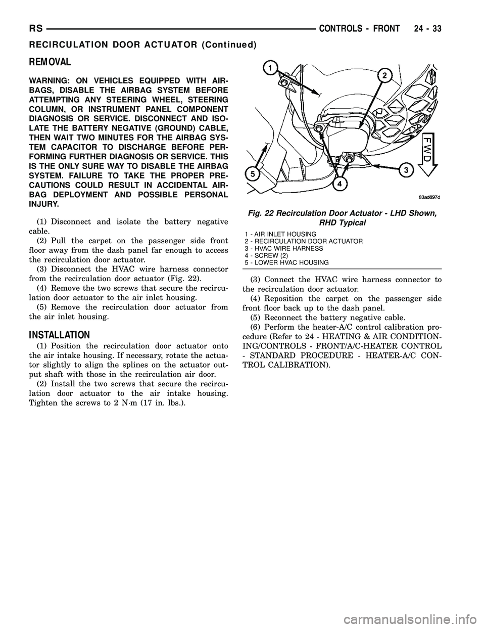
REMOVAL
WARNING: ON VEHICLES EQUIPPED WITH AIR-
BAGS, DISABLE THE AIRBAG SYSTEM BEFORE
ATTEMPTING ANY STEERING WHEEL, STEERING
COLUMN, OR INSTRUMENT PANEL COMPONENT
DIAGNOSIS OR SERVICE. DISCONNECT AND ISO-
LATE THE BATTERY NEGATIVE (GROUND) CABLE,
THEN WAIT TWO MINUTES FOR THE AIRBAG SYS-
TEM CAPACITOR TO DISCHARGE BEFORE PER-
FORMING FURTHER DIAGNOSIS OR SERVICE. THIS
IS THE ONLY SURE WAY TO DISABLE THE AIRBAG
SYSTEM. FAILURE TO TAKE THE PROPER PRE-
CAUTIONS COULD RESULT IN ACCIDENTAL AIR-
BAG DEPLOYMENT AND POSSIBLE PERSONAL
INJURY.
(1) Disconnect and isolate the battery negative
cable.
(2) Pull the carpet on the passenger side front
floor away from the dash panel far enough to access
the recirculation door actuator.
(3) Disconnect the HVAC wire harness connector
from the recirculation door actuator (Fig. 22).
(4) Remove the two screws that secure the recircu-
lation door actuator to the air inlet housing.
(5) Remove the recirculation door actuator from
the air inlet housing.
INSTALLATION
(1) Position the recirculation door actuator onto
the air intake housing. If necessary, rotate the actua-
tor slightly to align the splines on the actuator out-
put shaft with those in the recirculation air door.
(2) Install the two screws that secure the recircu-
lation door actuator to the air intake housing.
Tighten the screws to 2 N´m (17 in. lbs.).(3) Connect the HVAC wire harness connector to
the recirculation door actuator.
(4) Reposition the carpet on the passenger side
front floor back up to the dash panel.
(5) Reconnect the battery negative cable.
(6) Perform the heater-A/C control calibration pro-
cedure (Refer to 24 - HEATING & AIR CONDITION-
ING/CONTROLS - FRONT/A/C-HEATER CONTROL
- STANDARD PROCEDURE - HEATER-A/C CON-
TROL CALIBRATION).
Fig. 22 Recirculation Door Actuator - LHD Shown,
RHD Typical
1 - AIR INLET HOUSING
2 - RECIRCULATION DOOR ACTUATOR
3 - HVAC WIRE HARNESS
4 - SCREW (2)
5 - LOWER HVAC HOUSING
RSCONTROLS - FRONT24-33
RECIRCULATION DOOR ACTUATOR (Continued)
Page 2460 of 2585
SERVICE PORT VALVE CORE
DESCRIPTION.........................94
REMOVAL.............................94
INSTALLATION.........................94SUCTION LINE
REMOVAL.............................94
INSTALLATION.........................95
PLUMBING - FRONT
DESCRIPTION - REFRIGERANT LINE
The refrigerant lines and hoses are used to carry
the refrigerant between the various air conditioning
system components. A barrier hose design with a
nylon tube, which is sandwiched between rubber lay-
ers, is used for the R-134a air conditioning system on
this vehicle. This nylon tube helps to further contain
the R-134a refrigerant, which has a smaller molecu-
lar structure than R-12 refrigerant. The ends of the
refrigerant hoses are made from lightweight alumi-
num or steel, and commonly use braze-less fittings.
Any kinks or sharp bends in the refrigerant plumb-
ing will reduce the capacity of the entire air condi-
tioning system. Kinks and sharp bends reduce the
flow of refrigerant in the system. A good rule for the
flexible hose refrigerant lines is to keep the radius of
all bends at least ten times the diameter of the hose.
In addition, the flexible hose refrigerant lines should
be routed so they are at least 80 millimeters (3
inches) from an exhaust manifold.
OPERATION- REFRIGERANT LINES
High pressures are produced in the refrigerant sys-
tem when the air conditioning compressor is operat-
ing. Extreme care must be exercised to make sure
that each of the refrigerant system connections is
pressure-tight and leak free. It is a good practice to
inspect all flexible hose refrigerant lines at least once
a year to make sure they are in good condition and
properly routed.
The refrigerant lines and hoses are coupled with
other components of the HVAC system with either
O-rings or dual plane seals.
The refrigerant lines and hoses cannot be repaired
and, if faulty or damaged, they must be replaced.
WARNING
ENGINE COOLING SYSTEM
WARNING: THE ENGINE COOLING SYSTEM IS
DESIGNED TO DEVELOP INTERNAL PRESSURES
OF 97 TO 123 KILOPASCALS (14 TO 18 POUNDS
PER SQUARE INCH). DO NOT REMOVE OR
LOOSEN THE COOLANT PRESSURE CAP, CYLIN-
DER BLOCK DRAIN PLUGS, RADIATOR DRAIN,
RADIATOR HOSES, HEATER HOSES, OR HOSE
CLAMPS WHILE THE ENGINE COOLING SYSTEM ISHOT AND UNDER PRESSURE. FAILURE TO
OBSERVE THIS WARNING CAN RESULT IN SERI-
OUS BURNS FROM THE HEATED ENGINE COOL-
ANT. ALLOW THE VEHICLE TO COOL FOR A
MINIMUM OF 15 MINUTES BEFORE OPENING THE
COOLING SYSTEM FOR SERVICE.
A/C SYSTEM
WARNING: THE AIR CONDITIONING SYSTEM CON-
TAINS REFRIGERANT UNDER HIGH PRESSURE.
SEVERE PERSONAL INJURY MAY RESULT FROM
IMPROPER SERVICE PROCEDURES. REPAIRS
SHOULD ONLY BE PERFORMED BY QUALIFIED
SERVICE PERSONNEL.
AVOID BREATHING THE REFRIGERANT AND
REFRIGERANT OIL VAPOR OR MIST. EXPOSURE
MAY IRRITATE THE EYES, NOSE, AND/OR THROAT.
WEAR EYE PROTECTION WHEN SERVICING THE
AIR CONDITIONING REFRIGERANT SYSTEM. SERI-
OUS EYE INJURY CAN RESULT FROM DIRECT
CONTACT WITH THE REFRIGERANT. IF EYE CON-
TACT OCCURS, SEEK MEDICAL ATTENTION IMME-
DIATELY.
DO NOT EXPOSE THE REFRIGERANT TO OPEN
FLAME. POISONOUS GAS IS CREATED WHEN
REFRIGERANT IS BURNED. AN ELECTRONIC LEAK
DETECTOR IS RECOMMENDED.
IF ACCIDENTAL SYSTEM DISCHARGE OCCURS,
VENTILATE THE WORK AREA BEFORE RESUMING
SERVICE. LARGE AMOUNTS OF REFRIGERANT
RELEASED IN A CLOSED WORK AREA WILL DIS-
PLACE THE OXYGEN AND CAUSE SUFFOCATION.
THE EVAPORATION RATE OF R-134a REFRIGER-
ANT AT AVERAGE TEMPERATURE AND ALTITUDE
IS EXTREMELY HIGH. AS A RESULT, ANYTHING
THAT COMES IN CONTACT WITH THE REFRIGER-
ANT WILL FREEZE. ALWAYS PROTECT THE SKIN
OR DELICATE OBJECTS FROM DIRECT CONTACT
WITH THE REFRIGERANT.
THE R-134a SERVICE EQUIPMENT OR THE VEHI-
CLE REFRIGERANT SYSTEM SHOULD NOT BE
PRESSURE TESTED OR LEAK TESTED WITH COM-
PRESSED AIR. SOME MIXTURES OF AIR AND
R-134a HAVE BEEN SHOWN TO BE COMBUSTIBLE
AT ELEVATED PRESSURES. THESE MIXTURES ARE
POTENTIALLY DANGEROUS, AND MAY RESULT IN
FIRE OR EXPLOSION CAUSING INJURY OR PROP-
ERTY DAMAGE.
RSPLUMBING - FRONT24-65
Page 2478 of 2585
(8) Lubricate new rubber O-ring seals with clean
refrigerant oil and install them on the front liquid
line rear section and suction line fittings for the
expansion valve.
(9) Connect the liquid line and suction line fittings
to the expansion valve.
(10) Install the nut that secures the suction line
and liquid line fittings to the stud on the expansion
valve. Tighten the nut to 23 N´m (17 ft. lbs.).
(11) Remove the tape or plugs from the liquid line
rear section fitting and the receiver/drier outlet port.
(12) Lubricate a new rubber O-ring seal with clean
refrigerant oil and install it on the liquid line fitting.
(13) Connect the liquid line fitting to the receiver/
drier outlet port.
(14) Install the screw that secures the liquid line
fitting to the receiver/drier. Tighten the screw to 11
N´m (97 in. lbs.).
(15) Connect the wire harness connector to the A/C
pressure transducer.
(16) Connect the drain tube to the wiper module
drain on the right side of the engine compartment.
(17) Install the air cleaner housing.
(18) Reconnect the battery negative cable.
(19) Evacuate the refrigerant system (Refer to 24 -
HEATING & AIR CONDITIONING/PLUMBING -
FRONT/REFRIGERANT - STANDARD PROCE-
DURE - REFRIGERANT SYSTEM EVACUATE).
(20) Charge the refrigerant system (Refer to 24 -
HEATING & AIR CONDITIONING/PLUMBING -
FRONT/REFRIGERANT - STANDARD PROCE-
DURE - REFRIGERANT SYSTEM CHARGE).
HEATER CORE
DESCRIPTION
The heater core is located in the distribution hous-
ing, which is attached to the HVAC housing, behind
the instrument panel. It is a heat exchanger made of
rows of tubes and fins. One end of the core is fitted
with a molded plastic tank, which includes integral
heater core inlet and outlet ports. Removable heater
core tubes attach to the ports by use of a sealing
plate secured with a screw to the heater core tank.
This removable heater core tube arrangement allows
the heater core to be serviced without removing the
HVAC housing from the vehicle.
OPERATION
Engine coolant is circulated through heater hoses
to the heater core at all times. As the coolant flows
through the heater core, heat removed from the
engine is transferred to the heater core fins and
tubes. Air directed through the heater core picks up
the heat from the heater core fins. The blend doorallows control of the heater output air temperature
by regulating the amount of air that is flowing
through the heater core within the HVAC housing.
The heater core cannot be repaired and, if faulty or
damaged, it must be replaced.
REMOVAL
REMOVAL - HEATER CORE TUBES
WARNING: ON VEHICLES EQUIPPED WITH AIR-
BAGS, DISABLE THE AIRBAG SYSTEM BEFORE
ATTEMPTING ANY STEERING WHEEL, STEERING
COLUMN, OR INSTRUMENT PANEL COMPONENT
DIAGNOSIS OR SERVICE. DISCONNECT AND ISO-
LATE THE BATTERY NEGATIVE (GROUND) CABLE,
THEN WAIT TWO MINUTES FOR THE AIRBAG SYS-
TEM CAPACITOR TO DISCHARGE BEFORE PER-
FORMING FURTHER DIAGNOSIS OR SERVICE. THIS
IS THE ONLY SURE WAY TO DISABLE THE AIRBAG
SYSTEM. FAILURE TO TAKE THE PROPER PRE-
CAUTIONS COULD RESULT IN ACCIDENTAL AIR-
BAG DEPLOYMENT AND POSSIBLE PERSONAL
INJURY.
(1) Drain the engine cooling system (Refer to 7 -
COOLING - STANDARD PROCEDURE - COOLING
SYSTEM DRAIN).
(2) Disconnect and isolate the battery negative
cable.
(3) Disconnect the heater hoses from the heater
core tubes (Refer to 24 - HEATING & AIR CONDI-
TIONING/PLUMBING/HEATER INLET HOSE -
REMOVAL) and (Refer to 24 - HEATING & AIR
CONDITIONING/PLUMBING/HEATER RETURN
HOSE - REMOVAL).
(4) Remove the silencer from beneath the driver
side end of the instrument panel.
NOTE: Take the proper precautions to protect the
carpeting below the heater core from spilled engine
coolant and have absorbent toweling readily avail-
able to clean up any spills.
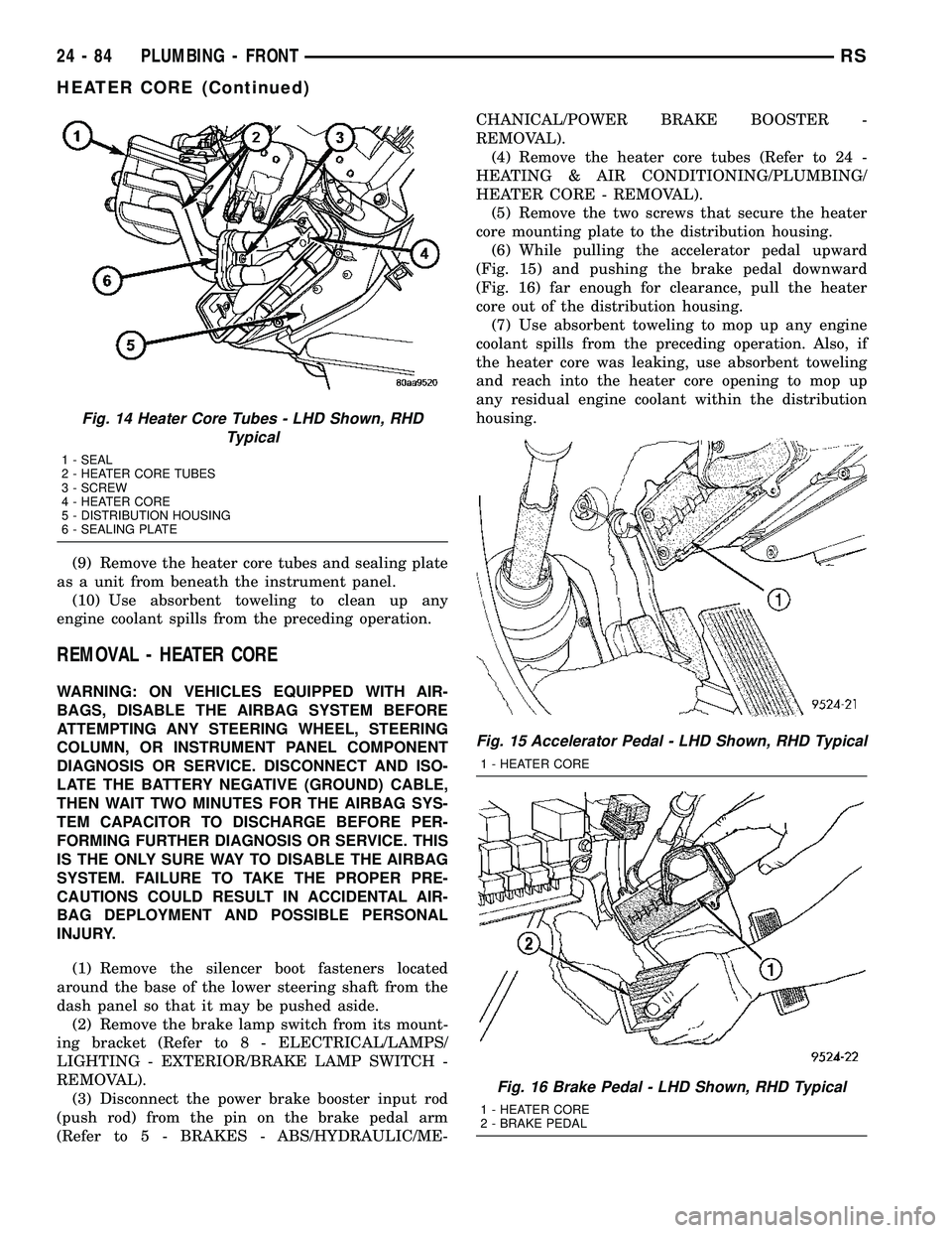
(5) Remove the screw that secures the heater core
tube sealing plate to the heater core supply and
return ports (Fig. 14).
(6) Push both heater core tubes simultaneously
toward the dash panel far enough to disengage their
fittings from the heater core supply and return ports.
(7) Install plugs in, or tape over the opened heater
core tube fittings and both heater core ports.
(8) Pull both heater core tubes simultaneously
slightly away from the distribution housing and rear-
ward far enough to disengage the engine compart-
ment ends of the tubes from the dash panel seal.
RSPLUMBING - FRONT24-83
EXPANSION VALVE (Continued)
Page 2479 of 2585
(9) Remove the heater core tubes and sealing plate
as a unit from beneath the instrument panel.
(10) Use absorbent toweling to clean up any
engine coolant spills from the preceding operation.
REMOVAL - HEATER CORE
WARNING: ON VEHICLES EQUIPPED WITH AIR-
BAGS, DISABLE THE AIRBAG SYSTEM BEFORE
ATTEMPTING ANY STEERING WHEEL, STEERING
COLUMN, OR INSTRUMENT PANEL COMPONENT
DIAGNOSIS OR SERVICE. DISCONNECT AND ISO-
LATE THE BATTERY NEGATIVE (GROUND) CABLE,
THEN WAIT TWO MINUTES FOR THE AIRBAG SYS-
TEM CAPACITOR TO DISCHARGE BEFORE PER-
FORMING FURTHER DIAGNOSIS OR SERVICE. THIS
IS THE ONLY SURE WAY TO DISABLE THE AIRBAG
SYSTEM. FAILURE TO TAKE THE PROPER PRE-
CAUTIONS COULD RESULT IN ACCIDENTAL AIR-
BAG DEPLOYMENT AND POSSIBLE PERSONAL
INJURY.
(1) Remove the silencer boot fasteners located
around the base of the lower steering shaft from the
dash panel so that it may be pushed aside.
(2) Remove the brake lamp switch from its mount-
ing bracket (Refer to 8 - ELECTRICAL/LAMPS/
LIGHTING - EXTERIOR/BRAKE LAMP SWITCH -
REMOVAL).
(3) Disconnect the power brake booster input rod
(push rod) from the pin on the brake pedal arm
(Refer to 5 - BRAKES - ABS/HYDRAULIC/ME-CHANICAL/POWER BRAKE BOOSTER -
REMOVAL).
(4) Remove the heater core tubes (Refer to 24 -
HEATING & AIR CONDITIONING/PLUMBING/
HEATER CORE - REMOVAL).
(5) Remove the two screws that secure the heater
core mounting plate to the distribution housing.
(6) While pulling the accelerator pedal upward
(Fig. 15) and pushing the brake pedal downward
(Fig. 16) far enough for clearance, pull the heater
core out of the distribution housing.
(7) Use absorbent toweling to mop up any engine
coolant spills from the preceding operation. Also, if
the heater core was leaking, use absorbent toweling
and reach into the heater core opening to mop up
any residual engine coolant within the distribution
housing.
Fig. 14 Heater Core Tubes - LHD Shown, RHD
Typical
1 - SEAL
2 - HEATER CORE TUBES
3 - SCREW
4 - HEATER CORE
5 - DISTRIBUTION HOUSING
6 - SEALING PLATE
Fig. 15 Accelerator Pedal - LHD Shown, RHD Typical
1 - HEATER CORE
Fig. 16 Brake Pedal - LHD Shown, RHD Typical
1 - HEATER CORE
2 - BRAKE PEDAL
24 - 84 PLUMBING - FRONTRS
HEATER CORE (Continued)