2004 CHRYSLER VOYAGER height
[x] Cancel search: heightPage 1477 of 2585
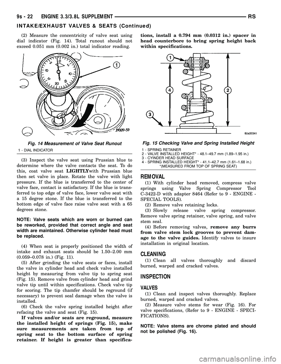
(2) Measure the concentricity of valve seat using
dial indicator (Fig. 14). Total runout should not
exceed 0.051 mm (0.002 in.) total indicator reading.
(3) Inspect the valve seat using Prussian blue to
determine where the valve contacts the seat. To do
this, coat valve seatLIGHTLYwith Prussian blue
then set valve in place. Rotate the valve with light
pressure. If the blue is transferred to the center of
valve face, contact is satisfactory. If the blue is trans-
ferred to top edge of valve face, lower valve seat with
a 15 degree stone. If the blue is transferred to the
bottom edge of valve face raise valve seat with a 65
degrees stone.
NOTE: Valve seats which are worn or burned can
be reworked, provided that correct angle and seat
width are maintained. Otherwise cylinder head must
be replaced.
(4) When seat is properly positioned the width of
intake and exhaust seats should be 1.50±2.00 mm
(0.059±0.078 in.) (Fig. 11).
(5) After grinding the valve seats or faces, install
the valve in cylinder head and check valve installed
height by measuring from valve tip to spring seat
(Fig. 15). Remove valve from cylinder head and grind
valve tip until within specifications. Check valve tip
for scoring. The tip chamfer should be reground (if
necessary) to prevent seal damage when the valve is
installed.
(6) Check the valve spring installed height after
refacing the valve and seat (Fig. 15).
If valves and/or seats are reground, measure
the installed height of springs (Fig. 15), make
sure measurements are taken from top of
spring seat to the bottom surface of spring
retainer. If height is greater than specifica-tions, install a 0.794 mm (0.0312 in.) spacer in
head counterbore to bring spring height back
within specifications.
REMOVAL
(1) With cylinder head removed, compress valve
springs using Valve Spring Compressor Tool
C-3422-D with adapter 8464 (Refer to 9 - ENGINE -
SPECIAL TOOLS).
(2) Remove valve retaining locks.
(3) Slowly release valve spring compressor.
Remove valve spring retainer, valve spring, and valve
stem seal.
(4) Before removing valves,remove any burrs
from valve stem lock grooves to prevent dam-
age to the valve guides.Identify valves to insure
installation in original location.
CLEANING
(1) Clean all valves thoroughly and discard
burned, warped and cracked valves.
INSPECTION
VALVES
(1) Clean and inspect valves thoroughly. Replace
burned, warped and cracked valves.
(2) Measure valve stems for wear (Fig. 16). For
valve specifications, (Refer to 9 - ENGINE - SPECI-
FICATIONS).
NOTE: Valve stems are chrome plated and should
not be polished (Fig. 16).
Fig. 14 Measurement of Valve Seat Runout
1 - DIAL INDICATOR
Fig. 15 Checking Valve and Spring Installed Height
1 - SPRING RETAINER
2 - VALVE INSTALLED HEIGHT* - 48.1±49.7 mm (1.89±1.95 in.)
3 - CYINDER HEAD SURFACE
4 - SPRING INSTALLED HEIGHT* - 41.1±42.7 mm (1.61±1.68 in.)
*(MEASURED FROM TOP OF SPRING SEAT)
9s - 22 ENGINE 3.3/3.8L SUPPLEMENTRS
INTAKE/EXHAUST VALVES & SEATS (Continued)
Page 1480 of 2585
(7) Install a spark plug adapter in the spark plug
hole. Connect air hose that can supply 620.5±689 kPa
(90±100 psi) of air pressure to adapter. This is to
hold valves in place while servicing components.
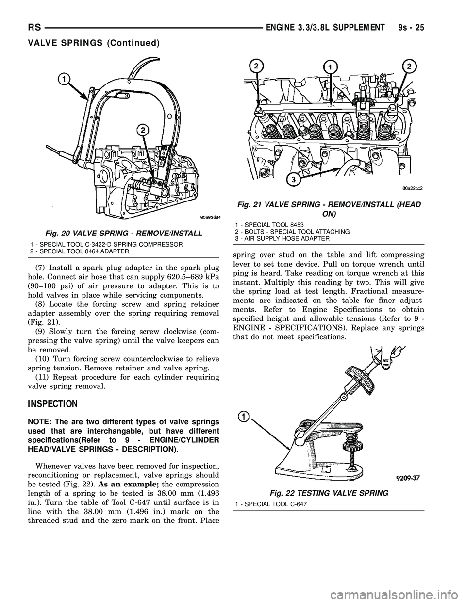
(8) Locate the forcing screw and spring retainer
adapter assembly over the spring requiring removal
(Fig. 21).
(9) Slowly turn the forcing screw clockwise (com-
pressing the valve spring) until the valve keepers can
be removed.
(10) Turn forcing screw counterclockwise to relieve
spring tension. Remove retainer and valve spring.
(11) Repeat procedure for each cylinder requiring
valve spring removal.
INSPECTION
NOTE: The are two different types of valve springs
used that are interchangable, but have different
specifications(Refer to 9 - ENGINE/CYLINDER
HEAD/VALVE SPRINGS - DESCRIPTION).
Whenever valves have been removed for inspection,
reconditioning or replacement, valve springs should
be tested (Fig. 22).As an example;the compression
length of a spring to be tested is 38.00 mm (1.496
in.). Turn the table of Tool C-647 until surface is in
line with the 38.00 mm (1.496 in.) mark on the
threaded stud and the zero mark on the front. Placespring over stud on the table and lift compressing
lever to set tone device. Pull on torque wrench until
ping is heard. Take reading on torque wrench at this
instant. Multiply this reading by two. This will give
the spring load at test length. Fractional measure-
ments are indicated on the table for finer adjust-
ments. Refer to Engine Specifications to obtain
specified height and allowable tensions (Refer to 9 -
ENGINE - SPECIFICATIONS). Replace any springs
that do not meet specifications.
Fig. 20 VALVE SPRING - REMOVE/INSTALL
1 - SPECIAL TOOL C-3422-D SPRING COMPRESSOR
2 - SPECIAL TOOL 8464 ADAPTER
Fig. 21 VALVE SPRING - REMOVE/INSTALL (HEAD
ON)
1 - SPECIAL TOOL 8453
2 - BOLTS - SPECIAL TOOL ATTACHING
3 - AIR SUPPLY HOSE ADAPTER
Fig. 22 TESTING VALVE SPRING
1 - SPECIAL TOOL C-647
RSENGINE 3.3/3.8L SUPPLEMENT9s-25
VALVE SPRINGS (Continued)
Page 1481 of 2585
INSTALLATION
INSTALLATION - CYLINDER HEAD OFF
(1) If removed, install a new valve stem seal (Refer
to 9 - ENGINE/CYLINDER HEAD/VALVE STEM
SEALS - INSTALLATION).
(2) Position valve spring and retainer on spring
seat.
(3) Using Special Tool C-3422-D with 8464 Adapter
(Fig. 20), compress the spring only enough to install
the valve retainer locks. Install valve retainer locks.
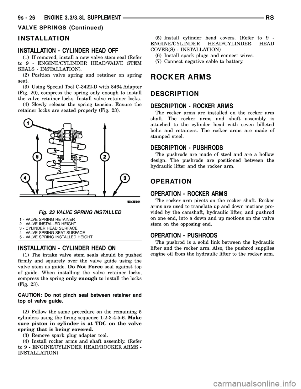
(4) Slowly release the spring tension. Ensure the
retainer locks are seated properly (Fig. 23).
INSTALLATION - CYLINDER HEAD ON
(1) The intake valve stem seals should be pushed
firmly and squarely over the valve guide using the
valve stem as guide.Do Not Forceseal against top
of guide. When installing the valve retainer locks,
compress the springonly enoughto install the locks
(Fig. 23).
CAUTION: Do not pinch seal between retainer and
top of valve guide.
(2) Follow the same procedure on the remaining 5
cylinders using the firing sequence 1-2-3-4-5-6.Make
sure piston in cylinder is at TDC on the valve
spring that is being covered.
(3) Remove spark plug adapter tool.
(4) Install rocker arms and shaft assembly. (Refer
to 9 - ENGINE/CYLINDER HEAD/ROCKER ARMS -
INSTALLATION)(5) Install cylinder head covers. (Refer to 9 -
ENGINE/CYLINDER HEAD/CYLINDER HEAD
COVER(S) - INSTALLATION)
(6) Install spark plugs and connect wires.
(7) Connect negative cable to battery.
ROCKER ARMS
DESCRIPTION
DESCRIPTION - ROCKER ARMS
The rocker arms are installed on the rocker arm
shaft. The rocker arms and shaft assembly is
attached to the cylinder head with seven billeted
bolts and retainers. The rocker arms are made of
stamped steel.
DESCRIPTION - PUSHRODS
The pushrods are made of steel and are a hollow
design. The pushrods are positioned between the
hydraulic lifter and the rocker arm.
OPERATION
OPERATION - ROCKER ARMS
The rocker arm pivots on the rocker shaft. Rocker
arms are used to translate up and down motions pro-
vided by the camshaft, hydraulic lifter, and pushrod
on one end, into a down and up motions on the valve
stem on the opposing end.
OPERATION - PUSHRODS
The pushrod is a solid link between the hydraulic
lifter and the rocker arm. Also, the pushrod supplies
engine oil from the hydraulic lifter to the rocker arm.
Fig. 23 VALVE SPRING INSTALLED
1 - VALVE SPRING RETAINER
2 - VALVE INSTALLED HEIGHT
3 - CYLINDER HEAD SURFACE
4 - VALVE SPRING SEAT SURFACE
5 - VALVE SPRING INSTALLED HEIGHT
9s - 26 ENGINE 3.3/3.8L SUPPLEMENTRS
VALVE SPRINGS (Continued)
Page 1499 of 2585
NOTE: If the rear fascia is to not to be removed for
other service issues use the step below.
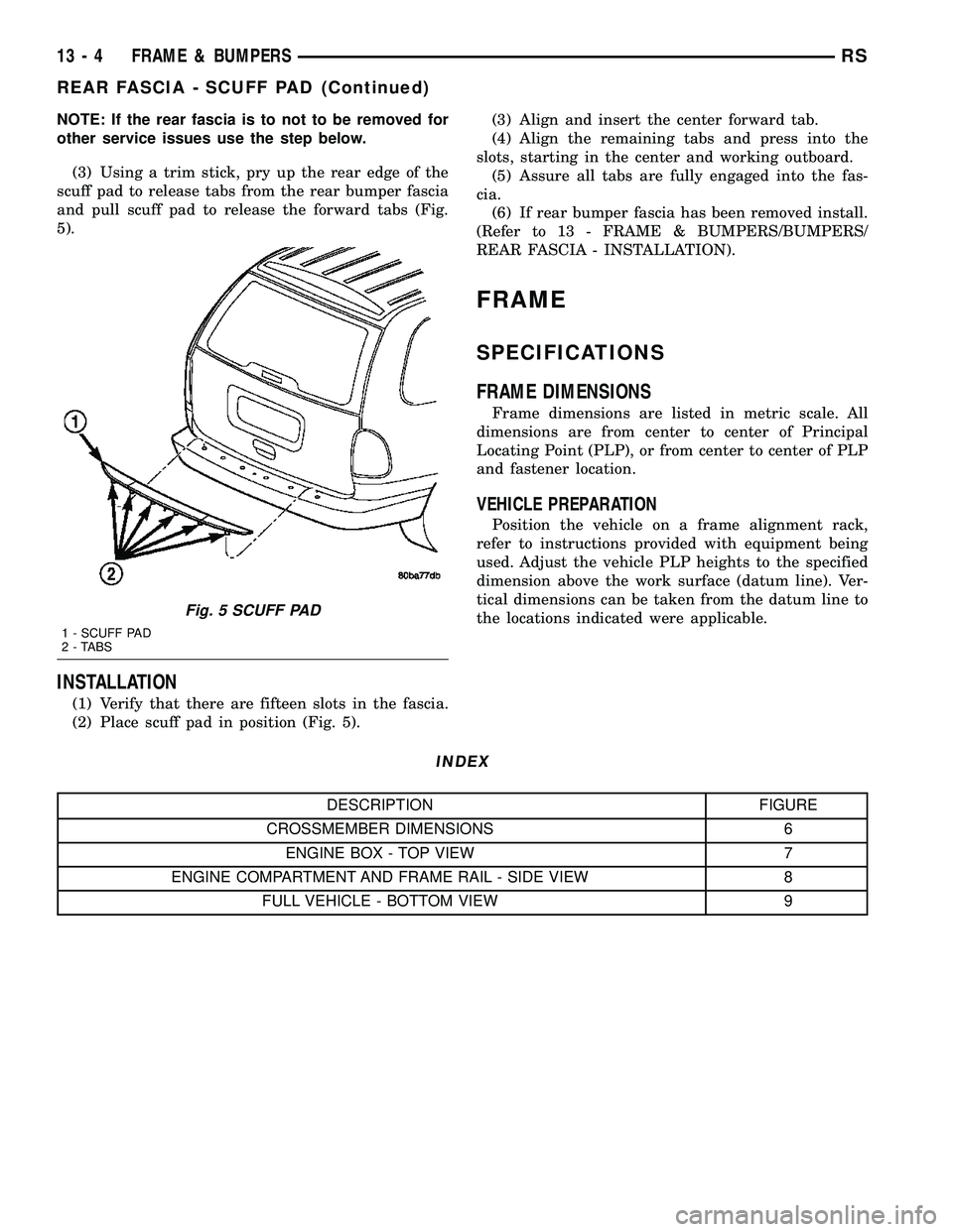
(3) Using a trim stick, pry up the rear edge of the
scuff pad to release tabs from the rear bumper fascia
and pull scuff pad to release the forward tabs (Fig.
5).
INSTALLATION
(1) Verify that there are fifteen slots in the fascia.
(2) Place scuff pad in position (Fig. 5).(3) Align and insert the center forward tab.
(4) Align the remaining tabs and press into the
slots, starting in the center and working outboard.
(5) Assure all tabs are fully engaged into the fas-
cia.
(6) If rear bumper fascia has been removed install.
(Refer to 13 - FRAME & BUMPERS/BUMPERS/
REAR FASCIA - INSTALLATION).
FRAME
SPECIFICATIONS
FRAME DIMENSIONS
Frame dimensions are listed in metric scale. All
dimensions are from center to center of Principal
Locating Point (PLP), or from center to center of PLP
and fastener location.
VEHICLE PREPARATION
Position the vehicle on a frame alignment rack,
refer to instructions provided with equipment being
used. Adjust the vehicle PLP heights to the specified
dimension above the work surface (datum line). Ver-
tical dimensions can be taken from the datum line to
the locations indicated were applicable.
INDEX
DESCRIPTION FIGURE
CROSSMEMBER DIMENSIONS 6
ENGINE BOX - TOP VIEW 7
ENGINE COMPARTMENT AND FRAME RAIL - SIDE VIEW 8
FULL VEHICLE - BOTTOM VIEW 9
Fig. 5 SCUFF PAD
1 - SCUFF PAD
2 - TABS
13 - 4 FRAME & BUMPERSRS
REAR FASCIA - SCUFF PAD (Continued)
Page 2092 of 2585
TIRES
DESCRIPTION
DESCRIPTION - TIRE
Tires are designed and engineered for each specific
vehicle. They provide the best overall performance
for normal operation. The ride and handling charac-
teristics match the vehicle's requirements. With
proper care they will give excellent reliability, trac-
tion, skid resistance, and tread life.
Driving habits have more effect on tire life than
any other factor. Careful drivers will obtain, in most
cases, much greater mileage than severe use or care-
less drivers. A few of the driving habits which will
shorten the life of any tire are:
²Rapid acceleration
²Severe application of brakes
²High-speed driving
²Taking turns at excessive speeds
²Striking curbs and other obstacles
²Operating vehicle with over or under inflated
tire pressures
Radial ply tires are more prone to irregular tread
wear. It is important to follow the tire rotation inter-
val shown in the section on Tire Rotation. This will
help to achieve a greater tread-life potential.
TIRE IDENTIFICATION
Tire type, size, load index and speed rating are
encoded in the letters and numbers imprinted on the
side wall of the tire. Refer to the Tire Identification
chart to decipher the code. For example purposes, the
tire size P225/60 R 16 97 T is used in the chart. An
All Season type tire will also have eitherM+S,M&
SorM-S(indicating mud and snow traction)
imprinted on the side wall. An Extra or Light Load
marking ªXLº or ªLLº may also be listed on the side-
wall. The absence of an ªXLº or ªLLº marking infers
a standard load tire.
TIRE IDENTIFICATION
PTIRE TYPE (Not
present on all tires)P - Passenger
T - Temporary
C - Commercial
LT - Light Truck
225SECTIONAL WIDTHSHOWN IN
MILLIMETERS
60ASPECT RATIOSECTIONAL HEIGHT
÷ SECTIONAL WIDTH
(Refer to Aspect Ratio
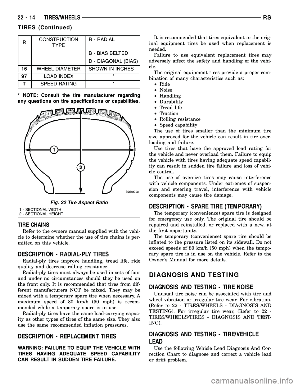
Figure 22 )
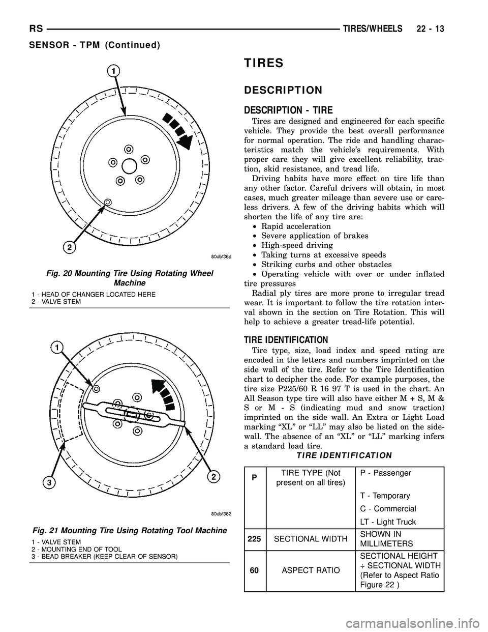
Fig. 20 Mounting Tire Using Rotating Wheel
Machine
1 - HEAD OF CHANGER LOCATED HERE
2 - VALVE STEM
Fig. 21 Mounting Tire Using Rotating Tool Machine
1 - VALVE STEM
2 - MOUNTING END OF TOOL
3 - BEAD BREAKER (KEEP CLEAR OF SENSOR)
RSTIRES/WHEELS22-13
SENSOR - TPM (Continued)
Page 2093 of 2585
RCONSTRUCTION
TYPER - RADIAL
B - BIAS BELTED
D - DIAGONAL (BIAS)
16WHEEL DIAMETER SHOWN IN INCHES
97LOAD INDEX *
TSPEED RATING *
* NOTE: Consult the tire manufacturer regarding
any questions on tire specifications or capabilities.
TIRE CHAINS
Refer to the owners manual supplied with the vehi-
cle to determine whether the use of tire chains is per-
mitted on this vehicle.
DESCRIPTION - RADIAL-PLY TIRES
Radial-ply tires improve handling, tread life, ride
quality and decrease rolling resistance.
Radial-ply tires must always be used in sets of four
and under no circumstances should they be used on
the front only. It is recommended that tires from dif-
ferent manufacturers NOT be mixed. They may be
mixed with a temporary spare tire when necessary. A
maximum speed of 80 km/h (50 mph) is recom-
mended while a temporary spare is in use.
Radial-ply tires have the same load-carrying capac-
ity as other types of tires of the same size. They also
use the same recommended inflation pressures.
DESCRIPTION - REPLACEMENT TIRES
WARNING: FAILURE TO EQUIP THE VEHICLE WITH
TIRES HAVING ADEQUATE SPEED CAPABILITY
CAN RESULT IN SUDDEN TIRE FAILURE.It is recommended that tires equivalent to the orig-
inal equipment tires be used when replacement is
needed.
Failure to use equivalent replacement tires may
adversely affect the safety and handling of the vehi-
cle.
The original equipment tires provide a proper com-
bination of many characteristics such as:
²Ride
²Noise
²Handling
²Durability
²Tread life
²Traction
²Rolling resistance
²Speed capability
The use of tires smaller than the minimum tire
size approved for the vehicle can result in tire over-
loading and failure.
Use tires that have the approved load rating for
the vehicle and never overload them. Failure to equip
the vehicle with tires having adequate speed capabil-
ity can result in sudden tire failure and loss of vehi-
cle control.
The use of oversize tires may cause interference
with vehicle components. Under extremes of suspen-
sion and steering travel, interference with vehicle
components may cause tire damage.
DESCRIPTION - SPARE TIRE (TEMPORARY)
The temporary (convenience) spare tire is designed
for emergency use only. The original tire should be
repaired and reinstalled, or replaced with a new, at
the first opportunity.
The temporary (convenience) spare tire should be
inflated to the pressure listed on its sidewall. Do not
exceed speeds of 80 km/h (50 mph) when the tempo-
rary spare tire is in use on the vehicle. Refer to the
Owner's Manual for more details.
DIAGNOSIS AND TESTING
DIAGNOSIS AND TESTING - TIRE NOISE
Unusual tire noise can be associated with tire and
wheel vibration or irregular tire wear. For vibration,
(Refer to 22 - TIRES/WHEELS - DIAGNOSIS AND
TESTING). For irregular tire wear, (Refer to 22 -
TIRES/WHEELS/TIRES - DIAGNOSIS AND TEST-
ING).
DIAGNOSIS AND TESTING - TIRE/VEHICLE
LEAD
Use the following Vehicle Lead Diagnosis And Cor-
rection Chart to diagnose and correct a vehicle lead
or drift problem.
Fig. 22 Tire Aspect Ratio
1 - SECTIONAL WIDTH
2 - SECTIONAL HEIGHT
22 - 14 TIRES/WHEELSRS
TIRES (Continued)
Page 2106 of 2585
TIRES
TABLE OF CONTENTS
page page
TIRES DESCRIPTION DESCRIPTION - TIRE ...................5
DESCRIPTION - RADIAL-PLY TIRES ........6
DESCRIPTION - REPLACEMENT TIRES .....6
DESCRIPTION - SPARE TIRE (TEMPORARY) ........................6
DIAGNOSIS AND TESTING DIAGNOSIS AND TESTING - TIRE NOISE ....6
DIAGNOSIS AND TESTING - TIRE/VEHICLE LEAD ................................6
DIAGNOSIS AND TESTING - TIRE WEAR PATTERNS ...........................8 DIAGNOSIS AND TESTING - TREAD WEAR
INDICATORS ..........................8
STANDARD PROCEDURE STANDARD PROCEDURE - TIRE INFLATIONPRESSURES ..........................8
STANDARD PROCEDURE - TIRE PRESSURE FOR HIGH SPEED
OPERATION ..........................9
STANDARD PROCEDURE - TIRE LEAK REPAIRING ...........................9
CLEANING - TIRES .....................10
TIRES
DESCRIPTION
DESCRIPTION - TIRE
Tires are designed and engineered for each specific
vehicle. They provide the best overall performance
for normal operation. The ride and handling charac-
teristics match the vehicle's requirements. With
proper care they will give excellent reliability, trac-
tion, skid resistance, and tread life. Driving habits have more effect on tire life than
any other factor. Careful drivers will obtain, in most
cases, much greater mileage than severe use or care-
less drivers. A few of the driving habits which will
shorten the life of any tire are: ² Rapid acceleration
² Severe application of brakes
² High-speed driving
² Taking turns at excessive speeds
² Striking curbs and other obstacles
² Operating vehicle with over or under inflated
tire pressures Radial ply tires are more prone to irregular tread
wear. It is important to follow the tire rotation inter-
val shown in the section on Tire Rotation. This will
help to achieve a greater tread-life potential.
TIRE IDENTIFICATION
Tire type, size, load index and speed rating are
encoded in the letters and numbers imprinted on the
side wall of the tire. Refer to the Tire Identification
chart to decipher the code. For example purposes, the tire size P225/60 R 16 97 T is used in the chart. An
All Season type tire will also have eithe
rM+S,M&
SorM-S (indicating mud and snow traction)
imprinted on the side wall. An Extra or Light Load
marking ªXLº or ªLLº may also be listed on the side-
wall. The absence of an ªXLº or ªLLº marking infers
a standard load tire.
TIRE IDENTIFICATION
P TIRE TYPE (Not
present on all tires) P - Passenger
T - Temporary
C - Commercial
LT - Light Truck
225 SECTIONAL WIDTH SHOWN IN
MILLIMETERS
60 ASPECT RATIO SECTIONAL HEIGHT
÷ SECTIONAL WIDTH
(Refer to Aspect Ratio
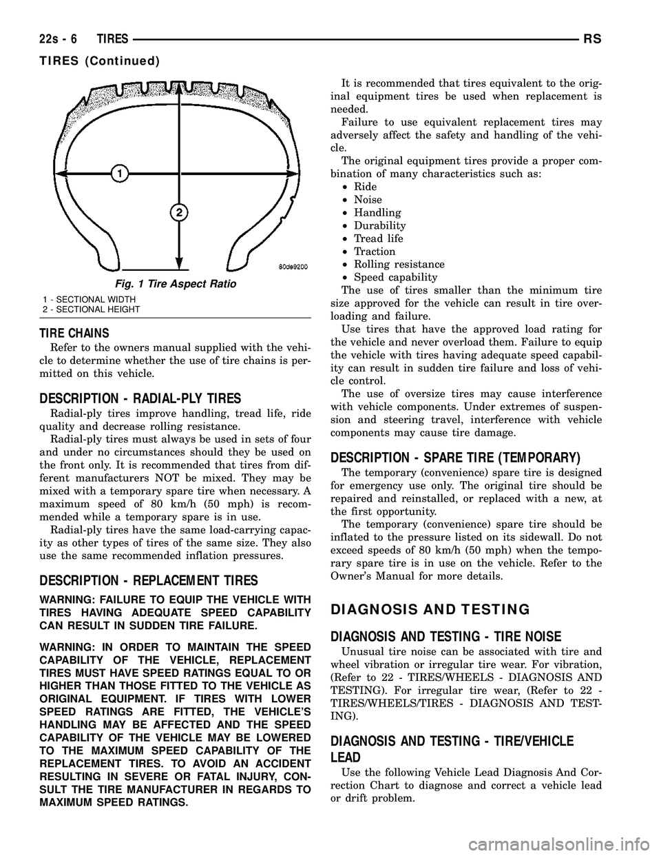
Figure 1 )
R CONSTRUCTION
TYPE R - RADIAL
B - BIAS BELTED
D - DIAGONAL (BIAS)
16 WHEEL DIAMETER SHOWN IN INCHES
97 LOAD INDEX *
T SPEED RATING *
* NOTE: Consult the tire manufacturer regarding
any questions on tire specifications or capabilities.
RS TIRES22s-5
Page 2107 of 2585
TIRE CHAINS
Refer to the owners manual supplied with the vehi-
cle to determine whether the use of tire chains is per-
mitted on this vehicle.
DESCRIPTION - RADIAL-PLY TIRES
Radial-ply tires improve handling, tread life, ride
quality and decrease rolling resistance. Radial-ply tires must always be used in sets of four
and under no circumstances should they be used on
the front only. It is recommended that tires from dif-
ferent manufacturers NOT be mixed. They may be
mixed with a temporary spare tire when necessary. A
maximum speed of 80 km/h (50 mph) is recom-
mended while a temporary spare is in use. Radial-ply tires have the same load-carrying capac-
ity as other types of tires of the same size. They also
use the same recommended inflation pressures.
DESCRIPTION - REPLACEMENT TIRES
WARNING: FAILURE TO EQUIP THE VEHICLE WITH
TIRES HAVING ADEQUATE SPEED CAPABILITY
CAN RESULT IN SUDDEN TIRE FAILURE.
WARNING: IN ORDER TO MAINTAIN THE SPEED
CAPABILITY OF THE VEHICLE, REPLACEMENT
TIRES MUST HAVE SPEED RATINGS EQUAL TO OR
HIGHER THAN THOSE FITTED TO THE VEHICLE AS
ORIGINAL EQUIPMENT. IF TIRES WITH LOWER
SPEED RATINGS ARE FITTED, THE VEHICLE'S
HANDLING MAY BE AFFECTED AND THE SPEED
CAPABILITY OF THE VEHICLE MAY BE LOWERED
TO THE MAXIMUM SPEED CAPABILITY OF THE
REPLACEMENT TIRES. TO AVOID AN ACCIDENT
RESULTING IN SEVERE OR FATAL INJURY, CON-
SULT THE TIRE MANUFACTURER IN REGARDS TO
MAXIMUM SPEED RATINGS. It is recommended that tires equivalent to the orig-
inal equipment tires be used when replacement is
needed. Failure to use equivalent replacement tires may
adversely affect the safety and handling of the vehi-
cle. The original equipment tires provide a proper com-
bination of many characteristics such as: ² Ride
² Noise
² Handling
² Durability
² Tread life
² Traction
² Rolling resistance
² Speed capability
The use of tires smaller than the minimum tire
size approved for the vehicle can result in tire over-
loading and failure. Use tires that have the approved load rating for
the vehicle and never overload them. Failure to equip
the vehicle with tires having adequate speed capabil-
ity can result in sudden tire failure and loss of vehi-
cle control. The use of oversize tires may cause interference
with vehicle components. Under extremes of suspen-
sion and steering travel, interference with vehicle
components may cause tire damage.
DESCRIPTION - SPARE TIRE (TEMPORARY)
The temporary (convenience) spare tire is designed
for emergency use only. The original tire should be
repaired and reinstalled, or replaced with a new, at
the first opportunity. The temporary (convenience) spare tire should be
inflated to the pressure listed on its sidewall. Do not
exceed speeds of 80 km/h (50 mph) when the tempo-
rary spare tire is in use on the vehicle. Refer to the
Owner's Manual for more details.
DIAGNOSIS AND TESTING
DIAGNOSIS AND TESTING - TIRE NOISE
Unusual tire noise can be associated with tire and
wheel vibration or irregular tire wear. For vibration,
(Refer to 22 - TIRES/WHEELS - DIAGNOSIS AND
TESTING). For irregular tire wear, (Refer to 22 -
TIRES/WHEELS/TIRES - DIAGNOSIS AND TEST-
ING).
DIAGNOSIS AND TESTING - TIRE/VEHICLE
LEAD
Use the following Vehicle Lead Diagnosis And Cor-
rection Chart to diagnose and correct a vehicle lead
or drift problem.
Fig. 1 Tire Aspect Ratio
1 - SECTIONAL WIDTH
2 - SECTIONAL HEIGHT
22s - 6 TIRESRS
TIRES (Continued)