2004 CHRYSLER VOYAGER height
[x] Cancel search: heightPage 1330 of 2585
INSTALLATION
INSTALLATION - CYLINDER HEAD ON
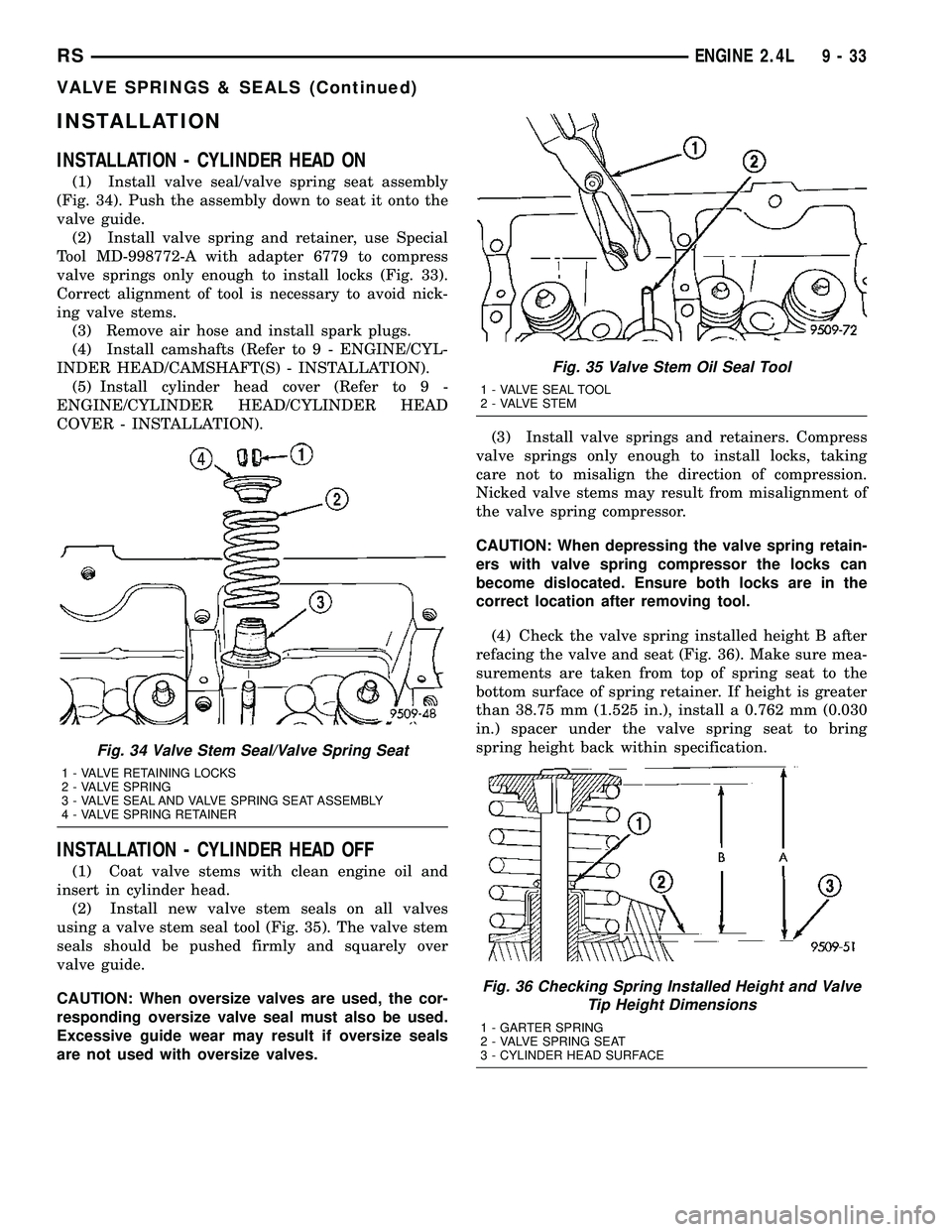
(1) Install valve seal/valve spring seat assembly
(Fig. 34). Push the assembly down to seat it onto the
valve guide.
(2) Install valve spring and retainer, use Special
Tool MD-998772-A with adapter 6779 to compress
valve springs only enough to install locks (Fig. 33).
Correct alignment of tool is necessary to avoid nick-
ing valve stems.
(3) Remove air hose and install spark plugs.
(4) Install camshafts (Refer to 9 - ENGINE/CYL-
INDER HEAD/CAMSHAFT(S) - INSTALLATION).
(5) Install cylinder head cover (Refer to 9 -
ENGINE/CYLINDER HEAD/CYLINDER HEAD
COVER - INSTALLATION).
INSTALLATION - CYLINDER HEAD OFF
(1) Coat valve stems with clean engine oil and
insert in cylinder head.
(2) Install new valve stem seals on all valves
using a valve stem seal tool (Fig. 35). The valve stem
seals should be pushed firmly and squarely over
valve guide.
CAUTION: When oversize valves are used, the cor-
responding oversize valve seal must also be used.
Excessive guide wear may result if oversize seals
are not used with oversize valves.(3) Install valve springs and retainers. Compress
valve springs only enough to install locks, taking
care not to misalign the direction of compression.
Nicked valve stems may result from misalignment of
the valve spring compressor.
CAUTION: When depressing the valve spring retain-
ers with valve spring compressor the locks can
become dislocated. Ensure both locks are in the
correct location after removing tool.
(4) Check the valve spring installed height B after
refacing the valve and seat (Fig. 36). Make sure mea-
surements are taken from top of spring seat to the
bottom surface of spring retainer. If height is greater
than 38.75 mm (1.525 in.), install a 0.762 mm (0.030
in.) spacer under the valve spring seat to bring
spring height back within specification.
Fig. 34 Valve Stem Seal/Valve Spring Seat
1 - VALVE RETAINING LOCKS
2 - VALVE SPRING
3 - VALVE SEAL AND VALVE SPRING SEAT ASSEMBLY
4 - VALVE SPRING RETAINER
Fig. 35 Valve Stem Oil Seal Tool
1 - VALVE SEAL TOOL
2 - VALVE STEM
Fig. 36 Checking Spring Installed Height and Valve
Tip Height Dimensions
1 - GARTER SPRING
2 - VALVE SPRING SEAT
3 - CYLINDER HEAD SURFACE
RSENGINE 2.4L9-33
VALVE SPRINGS & SEALS (Continued)
Page 1391 of 2585
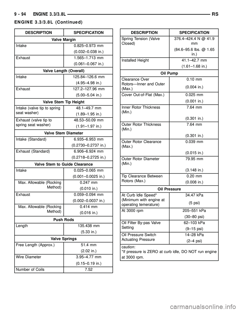
DESCRIPTION SPECIFICATION
Valve Margin
Intake 0.825±0.973 mm
(0.032±0.038 in.)
Exhaust 1.565±1.713 mm
(0.061±0.067 in.)
Valve Length (Overall)
Intake 125.84±126.6 mm
(4.95±4.98 in.)
Exhaust 127.2±127.96 mm
(5.00±5.04 in.)
Valve Stem Tip Height
Intake (valve tip to spring
seat washer)48.1±49.7 mm
(1.89±1.95 in.)
Exhaust (valve tip to
spring seat washer)48.53±50.09 mm
(1.91±1.97 in.)
Valve Stem Diameter
Intake (Standard) 6.935±6.953 mm
(0.2730±0.2737 in.)
Exhaust (Standard) 6.906±6.924 mm
(0.2718±0.2725 in.)
Valve Stem to Guide Clearance
Intake 0.025±0.065 mm
(0.001±0.0025 in.)
Max. Allowable (Rocking
Method)0.247 mm
(0.010 in.)
Exhaust 0.059±0.094 mm
(0.002±0.0037 in.)
Max. Allowable (Rocking
Method)0.414 mm
(0.016 in.)
Push Rods
Length 135.438 mm
(5.33 in.)
Valve Springs
Free Length (Approx.) 51.4 mm
(2.02 in.)
Wire Diameter 3.95±4.77 mm
(0.15±0.19 in.)
Number of Coils 7.52DESCRIPTION SPECIFICATION
Spring Tension (Valve
Closed)376.4±424.4 N @ 41.9
mm
(84.6±95.6 lbs. @ 1.65
in.)
Installed Height 41.1±42.7 mm
(1.61±1.68 in.)
Oil Pump
Clearance Over
RotorsÐInner and Outer
(Max.)0.10 mm
(0.004 in.)
Cover Out-of-Flat (Max.) 0.025 mm
(0.001 in.)
Inner Rotor Thickness
(Min.)7.64 mm
(0.301 in.)
Outer Rotor Thickness
(Min.)7.64 mm
(0.301 in.)
Outer Rotor Clearance
(Max.)0.039 mm
(0.015 in.)
Outer Rotor Diameter
(Min.)79.95 mm
(3.148 in.)
Tip Clearance Between
Rotors (Max.)0.20 mm
(0.008 in.)
Oil Pressure
At Curb Idle Speed*
(Minimum with engine at
operating temerature)34.47 kPa
(5 psi)
At 3000 rpm 205±551 kPa
(30±80 psi)
Oil Filter By-pas Valve
Setting62±103 kPa
(9±15 psi)
Oil Pressure Switch
Actuating Pressure14±28 kPa
(2±4 psi)
caution:
*If pressure is ZERO at curb idle, DO NOT run engine
at 3000 rpm.
9 - 94 ENGINE 3.3/3.8LRS
ENGINE 3.3/3.8L (Continued)
Page 1402 of 2585
(4) When seat is properly positioned the width of
intake and exhaust seats should be 1.50±2.00 mm
(0.059±0.078 in.) (Fig. 27).
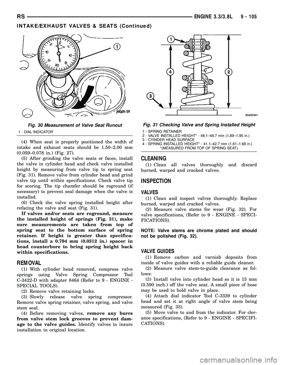
(5) After grinding the valve seats or faces, install
the valve in cylinder head and check valve installed
height by measuring from valve tip to spring seat
(Fig. 31). Remove valve from cylinder head and grind
valve tip until within specifications. Check valve tip
for scoring. The tip chamfer should be reground (if
necessary) to prevent seal damage when the valve is
installed.
(6) Check the valve spring installed height after
refacing the valve and seat (Fig. 31).
If valves and/or seats are reground, measure
the installed height of springs (Fig. 31), make
sure measurements are taken from top of
spring seat to the bottom surface of spring
retainer. If height is greater than specifica-
tions, install a 0.794 mm (0.0312 in.) spacer in
head counterbore to bring spring height back
within specifications.
REMOVAL
(1) With cylinder head removed, compress valve
springs using Valve Spring Compressor Tool
C-3422-D with adapter 8464 (Refer to 9 - ENGINE -
SPECIAL TOOLS).
(2) Remove valve retaining locks.
(3) Slowly release valve spring compressor.
Remove valve spring retainer, valve spring, and valve
stem seal.
(4) Before removing valves,remove any burrs
from valve stem lock grooves to prevent dam-
age to the valve guides.Identify valves to insure
installation in original location.
CLEANING
(1) Clean all valves thoroughly and discard
burned, warped and cracked valves.
INSPECTION
VALVES
(1) Clean and inspect valves thoroughly. Replace
burned, warped and cracked valves.
(2) Measure valve stems for wear (Fig. 32). For
valve specifications, (Refer to 9 - ENGINE - SPECI-
FICATIONS).
NOTE: Valve stems are chrome plated and should
not be polished (Fig. 32).
VALVE GUIDES
(1) Remove carbon and varnish deposits from
inside of valve guides with a reliable guide cleaner.
(2) Measure valve stem-to-guide clearance as fol-
lows:
(3) Install valve into cylinder head so it is 15 mm
(0.590 inch.) off the valve seat. A small piece of hose
may be used to hold valve in place.
(4) Attach dial indicator Tool C-3339 to cylinder
head and set it at right angle of valve stem being
measured (Fig. 33).
(5) Move valve to and from the indicator. For cler-
ance specifications, (Refer to 9 - ENGINE - SPECIFI-
CATIONS).
Fig. 30 Measurement of Valve Seat Runout
1 - DIAL INDICATOR
Fig. 31 Checking Valve and Spring Installed Height
1 - SPRING RETAINER
2 - VALVE INSTALLED HEIGHT* - 48.1±49.7 mm (1.89±1.95 in.)
3 - CYINDER HEAD SURFACE
4 - SPRING INSTALLED HEIGHT* - 41.1±42.7 mm (1.61±1.68 in.)
*(MEASURED FROM TOP OF SPRING SEAT)
RSENGINE 3.3/3.8L9 - 105
INTAKE/EXHAUST VALVES & SEATS (Continued)
Page 1405 of 2585
(11) Repeat procedure for each cylinder requiring
valve spring removal.
INSPECTION
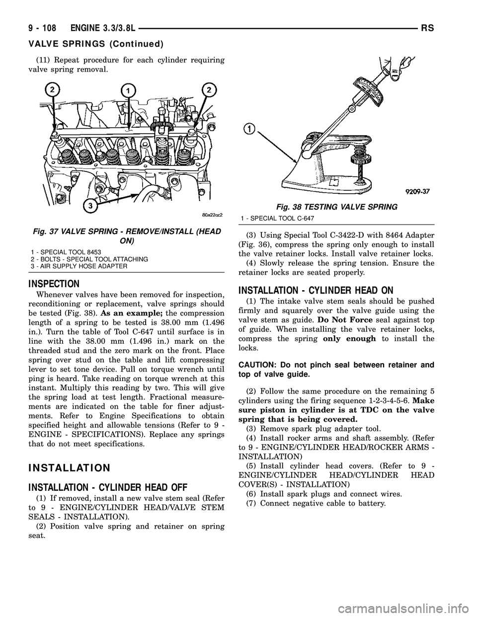
Whenever valves have been removed for inspection,
reconditioning or replacement, valve springs should
be tested (Fig. 38).As an example;the compression
length of a spring to be tested is 38.00 mm (1.496
in.). Turn the table of Tool C-647 until surface is in
line with the 38.00 mm (1.496 in.) mark on the
threaded stud and the zero mark on the front. Place
spring over stud on the table and lift compressing
lever to set tone device. Pull on torque wrench until
ping is heard. Take reading on torque wrench at this
instant. Multiply this reading by two. This will give
the spring load at test length. Fractional measure-
ments are indicated on the table for finer adjust-
ments. Refer to Engine Specifications to obtain
specified height and allowable tensions (Refer to 9 -
ENGINE - SPECIFICATIONS). Replace any springs
that do not meet specifications.
INSTALLATION
INSTALLATION - CYLINDER HEAD OFF
(1) If removed, install a new valve stem seal (Refer
to 9 - ENGINE/CYLINDER HEAD/VALVE STEM
SEALS - INSTALLATION).
(2) Position valve spring and retainer on spring
seat.(3) Using Special Tool C-3422-D with 8464 Adapter
(Fig. 36), compress the spring only enough to install
the valve retainer locks. Install valve retainer locks.
(4) Slowly release the spring tension. Ensure the
retainer locks are seated properly.
INSTALLATION - CYLINDER HEAD ON
(1) The intake valve stem seals should be pushed
firmly and squarely over the valve guide using the
valve stem as guide.Do Not Forceseal against top
of guide. When installing the valve retainer locks,
compress the springonly enoughto install the
locks.
CAUTION: Do not pinch seal between retainer and
top of valve guide.
(2) Follow the same procedure on the remaining 5
cylinders using the firing sequence 1-2-3-4-5-6.Make
sure piston in cylinder is at TDC on the valve
spring that is being covered.
(3) Remove spark plug adapter tool.
(4) Install rocker arms and shaft assembly. (Refer
to 9 - ENGINE/CYLINDER HEAD/ROCKER ARMS -
INSTALLATION)
(5) Install cylinder head covers. (Refer to 9 -
ENGINE/CYLINDER HEAD/CYLINDER HEAD
COVER(S) - INSTALLATION)
(6) Install spark plugs and connect wires.
(7) Connect negative cable to battery.
Fig. 37 VALVE SPRING - REMOVE/INSTALL (HEAD
ON)
1 - SPECIAL TOOL 8453
2 - BOLTS - SPECIAL TOOL ATTACHING
3 - AIR SUPPLY HOSE ADAPTER
Fig. 38 TESTING VALVE SPRING
1 - SPECIAL TOOL C-647
9 - 108 ENGINE 3.3/3.8LRS
VALVE SPRINGS (Continued)
Page 1459 of 2585
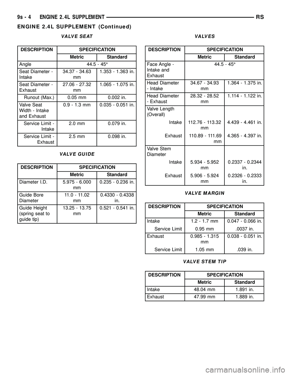
VALVE SEAT
DESCRIPTION SPECIFICATION
Metric Standard
Angle 44.5 - 45É
Seat Diameter -
Intake34.37 - 34.63
mm1.353 - 1.363 in.
Seat Diameter -
Exhaust27.06 - 27.32
mm1.065 - 1.075 in.
Runout (Max.) 0.05 mm 0.002 in.
Valve Seat
Width - Intake
and Exhaust0.9 - 1.3 mm 0.035 - 0.051 in.
Service Limit -
Intake2.0 mm 0.079 in.
Service Limit -
Exhaust2.5 mm 0.098 in.
VALVE GUIDE
DESCRIPTION SPECIFICATION
Metric Standard
Diameter I.D. 5.975 - 6.000
mm0.235 - 0.236 in.
Guide Bore
Diameter11.0 - 11.02
mm0.4330 - 0.4338
in.
Guide Height
(spring seat to
guide tip)13.25 - 13.75
mm0.521 - 0.541 in.
VALVES
DESCRIPTION SPECIFICATION
Metric Standard
Face Angle -
Intake and
Exhaust44.5 - 45É
Head Diameter
- Intake34.67 - 34.93
mm1.364 - 1.375 in.
Head Diameter
- Exhaust28.32 - 28.52
mm1.114 - 1.122 in.
Valve Length
(Overall)
Intake 112.76 - 113.32
mm4.439 - 4.461 in.
Exhaust 110.89 - 111.69
mm4.365 - 4.397 in.
Valve Stem
Diameter
Intake 5.934 - 5.952
mm0.2337 - 0.2344
in.
Exhaust 5.906 - 5.924
mm0.2326 - 0.2333
in.
VALVE MARGIN
DESCRIPTION SPECIFICATION
Metric Standard
Intake 1.2 - 1.7 mm 0.047 - 0.066 in.
Service Limit 0.95 mm .0037 in.
Exhaust 0.985 - 1.315
mm0.038 - 0.051 in.
Service Limit 1.05 mm .039 in.
VALVE STEM TIP
DESCRIPTION SPECIFICATION
Metric Standard
Intake 48.04 mm 1.891 in.
Exhaust 47.99 mm 1.889 in.
9s - 4 ENGINE 2.4L SUPPLEMENTRS
ENGINE 2.4L SUPPLEMENT (Continued)
Page 1460 of 2585
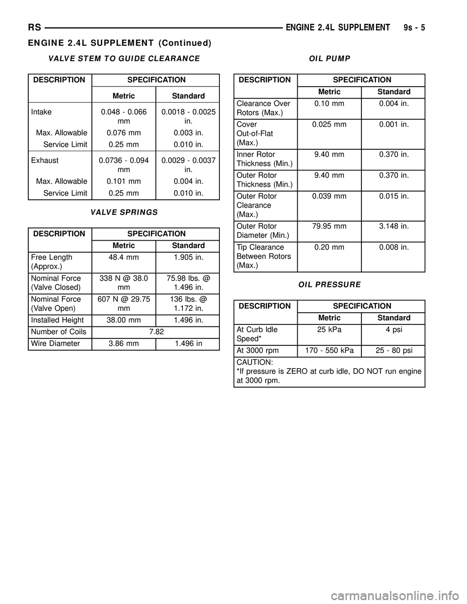
VALVE STEM TO GUIDE CLEARANCE
DESCRIPTION SPECIFICATION
Metric Standard
Intake 0.048 - 0.066
mm0.0018 - 0.0025
in.
Max. Allowable 0.076 mm 0.003 in.
Service Limit 0.25 mm 0.010 in.
Exhaust 0.0736 - 0.094
mm0.0029 - 0.0037
in.
Max. Allowable 0.101 mm 0.004 in.
Service Limit 0.25 mm 0.010 in.
VALVE SPRINGS
DESCRIPTION SPECIFICATION
Metric Standard
Free Length
(Approx.)48.4 mm 1.905 in.
Nominal Force
(Valve Closed)338 N @ 38.0
mm75.98 lbs. @
1.496 in.
Nominal Force
(Valve Open)607 N @ 29.75
mm136 lbs. @
1.172 in.
Installed Height 38.00 mm 1.496 in.
Number of Coils 7.82
Wire Diameter 3.86 mm 1.496 in
OIL PUMP
DESCRIPTION SPECIFICATION
Metric Standard
Clearance Over
Rotors (Max.)0.10 mm 0.004 in.
Cover
Out-of-Flat
(Max.)0.025 mm 0.001 in.
Inner Rotor
Thickness (Min.)9.40 mm 0.370 in.
Outer Rotor
Thickness (Min.)9.40 mm 0.370 in.
Outer Rotor
Clearance
(Max.)0.039 mm 0.015 in.
Outer Rotor
Diameter (Min.)79.95 mm 3.148 in.
Tip Clearance
Between Rotors
(Max.)0.20 mm 0.008 in.
OIL PRESSURE
DESCRIPTION SPECIFICATION
Metric Standard
At Curb Idle
Speed*25 kPa 4 psi
At 3000 rpm 170 - 550 kPa 25 - 80 psi
CAUTION:
*If pressure is ZERO at curb idle, DO NOT run engine
at 3000 rpm.
RSENGINE 2.4L SUPPLEMENT9s-5
ENGINE 2.4L SUPPLEMENT (Continued)
Page 1469 of 2585
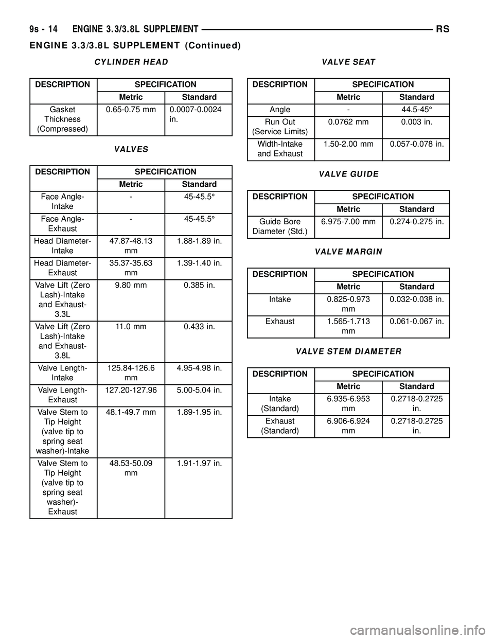
CYLINDER HEAD
DESCRIPTION SPECIFICATION
Metric Standard
Gasket
Thickness
(Compressed)0.65-0.75 mm 0.0007-0.0024
in.
VALVES
DESCRIPTION SPECIFICATION
Metric Standard
Face Angle-
Intake- 45-45.5É
Face Angle-
Exhaust- 45-45.5É
Head Diameter-
Intake47.87-48.13
mm1.88-1.89 in.
Head Diameter-
Exhaust35.37-35.63
mm1.39-1.40 in.
Valve Lift (Zero
Lash)-Intake
and Exhaust-
3.3L9.80 mm 0.385 in.
Valve Lift (Zero
Lash)-Intake
and Exhaust-
3.8L11.0 mm 0.433 in.
Valve Length-
Intake125.84-126.6
mm4.95-4.98 in.
Valve Length-
Exhaust127.20-127.96 5.00-5.04 in.
Valve Stem to
Tip Height
(valve tip to
spring seat
washer)-Intake48.1-49.7 mm 1.89-1.95 in.
Valve Stem to
Tip Height
(valve tip to
spring seat
washer)-
Exhaust48.53-50.09
mm1.91-1.97 in.
VALVE SEAT
DESCRIPTION SPECIFICATION
Metric Standard
Angle - 44.5-45É
Run Out
(Service Limits)0.0762 mm 0.003 in.
Width-Intake
and Exhaust1.50-2.00 mm 0.057-0.078 in.
VALVE GUIDE
DESCRIPTION SPECIFICATION
Metric Standard
Guide Bore
Diameter (Std.)6.975-7.00 mm 0.274-0.275 in.
VALVE MARGIN
DESCRIPTION SPECIFICATION
Metric Standard
Intake 0.825-0.973
mm0.032-0.038 in.
Exhaust 1.565-1.713
mm0.061-0.067 in.
VALVE STEM DIAMETER
DESCRIPTION SPECIFICATION
Metric Standard
Intake
(Standard)6.935-6.953
mm0.2718-0.2725
in.
Exhaust
(Standard)6.906-6.924
mm0.2718-0.2725
in.
9s - 14 ENGINE 3.3/3.8L SUPPLEMENTRS
ENGINE 3.3/3.8L SUPPLEMENT (Continued)
Page 1470 of 2585
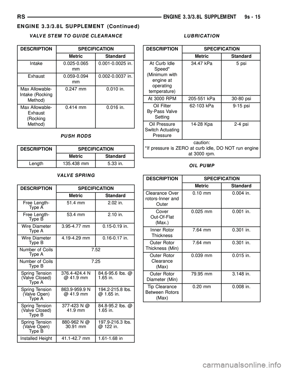
VALVE STEM TO GUIDE CLEARANCE
DESCRIPTION SPECIFICATION
Metric Standard
Intake 0.025-0.065
mm0.001-0.0025 in.
Exhaust 0.059-0.094
mm0.002-0.0037 in.
Max Allowable-
Intake (Rocking
Method)0.247 mm 0.010 in.
Max Allowable-
Exhaust
(Rocking
Method)0.414 mm 0.016 in.
PUSH RODS
DESCRIPTION SPECIFICATION
Metric Standard
Length 135.438 mm 5.33 in.
VALVE SPRING
DESCRIPTION SPECIFICATION
Metric Standard
Free Length-
Type A51.4 mm 2.02 in.
Free Length-
Type B53.4 mm 2.10 in.
Wire Diameter
Type A3.95-4.77 mm 0.15-0.19 in.
Wire Diameter
Type B4.19-4.29 mm 0.16-0.17 in.
Number of Coils
Type A7.52
Number of Coils
Type B7.25
Spring Tension
(Valve Closed)
Type A376.4-424.4 N
@ 41.9 mm84.6-95.6 lbs. @
1.65 in.
Spring Tension
(Valve Open)
Type A863.9-959.9 N
@ 41.9 mm194.2-215.8 lbs.
@ 1.65 in.
Spring Tension
(Valve Closed)
Type B377-423 N @
41.9 mm84.8-95.2 lbs. @
1.65 in.
Spring Tension
(Valve Open)
Type B880-962 N @
30.91 mm197.9-216.3 lbs.
@ 122 in.
Installed Height 41.1-42.7 mm 1.61-1.68 in
LUBRICATION
DESCRIPTION SPECIFICATION
Metric Standard
At Curb Idle
Speed*
(Minimum with
engine at
operating
temperature)34.47 kPa 5 psi
At 3000 RPM 205-551 kPa 30-80 psi
Oil Filter
By-Pass Valve
Setting62-103 kPa 9-15 psi
Oil Pressure
Switch Actuating
Pressure14-28 Kpa 2-4 psi
caution:
*If pressure is ZERO at curb idle, DO NOT run engine
at 3000 rpm.
OIL PUMP
DESCRIPTION SPECIFICATION
Metric Standard
Clearance Over
rotors-Inner and
Outer0.10 mm 0.004 in.
Cover
Out-Of-Flat
(Max.)0.025 mm 0.001 in.
Inner Rotor
Thickness7.64 mm 0.301 in.
Outer Rotor
Thickness (Min)7.64 mm 0.301 in.
Outer Rotor
Clearance
(Max)0.039 mm 0.015 in.
Outer Rotor
Diameter (Min)79.95 mm 3.148 in.
Tip Clearance
Between Rotors
(Max)0.20 mm 0.008 in.
RSENGINE 3.3/3.8L SUPPLEMENT9s-15
ENGINE 3.3/3.8L SUPPLEMENT (Continued)