2004 CHRYSLER VOYAGER brake
[x] Cancel search: brakePage 1831 of 2585
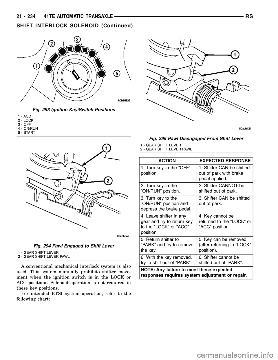
A conventional mechanical interlock system is also
used. This system manually prohibits shifter move-
ment when the ignition switch is in the LOCK or
ACC positions. Solenoid operation is not required in
these key positions.
For intended BTSI system operation, refer to the
following chart:
ACTION EXPECTED RESPONSE
1. Turn key to the9OFF9
position.1. Shifter CAN be shifted
out of park with brake
pedal applied.
2. Turn key to the
9ON/RUN9position.2. Shifter CANNOT be
shifted out of park.
3. Turn key to the
9ON/RUN9position and
depress the brake pedal.3. Shifter CAN be shifted
out of park.
4. Leave shifter in any
gear and try to return key
to the9LOCK9or9ACC9
position.4. Key cannot be
returned to the9LOCK9or
9ACC9position.
5. Return shifter to
9PARK9and try to remove
the key.5. Key can be removed
(after returning to9LOCK9
position).
6. With the key removed,
try to shift out of9PARK9.6. Shifter cannot be
shifted out of9PARK9.
NOTE: Any failure to meet these expected
responses requires system adjustment or repair.
Fig. 293 Ignition Key/Switch Positions
1 - ACC
2 - LOCK
3 - OFF
4 - ON/RUN
5-START
Fig. 294 Pawl Engaged to Shift Lever
1 - GEAR SHIFT LEVER
2 - GEAR SHIFT LEVER PAWL
Fig. 295 Pawl Disengaged From Shift Lever
1 - GEAR SHIFT LEVER
2 - GEAR SHIFT LEVER PAWL
21 - 234 41TE AUTOMATIC TRANSAXLERS
SHIFT INTERLOCK SOLENOID (Continued)
Page 1832 of 2585
DIAGNOSIS AND TESTING - BRAKE/
TRANSMISSION SHIFT INTERLOCK SOLENOID
For intended BTSI system operation, refer to the
following chart:
ACTION EXPECTED RESPONSE
1. Turn key to the9OFF9
position.1. Shifter CAN be shifted
out of park with brake
pedal applied.
2. Turn key to the
9ON/RUN9position.2. Shifter CANNOT be
shifted out of park.
3. Turn key to the
9ON/RUN9position and
depress the brake pedal.3. Shifter CAN be shifted
out of park.
4. Leave shifter in any
gear and try to return key
to the9LOCK9or9ACC9
position.4. Key cannot be
returned to the9LOCK9or
9ACC9position.
5. Return shifter to
9PARK9and try to remove
the key.5. Key can be removed
(after returning to9LOCK9
position).
6. With the key removed,
try to shift out of9PARK9.6. Shifter cannot be
shifted out of9PARK9.
NOTE: Any failure to meet these expected
responses requires system repair. Refer to the
appropriate Diagnostic Information.
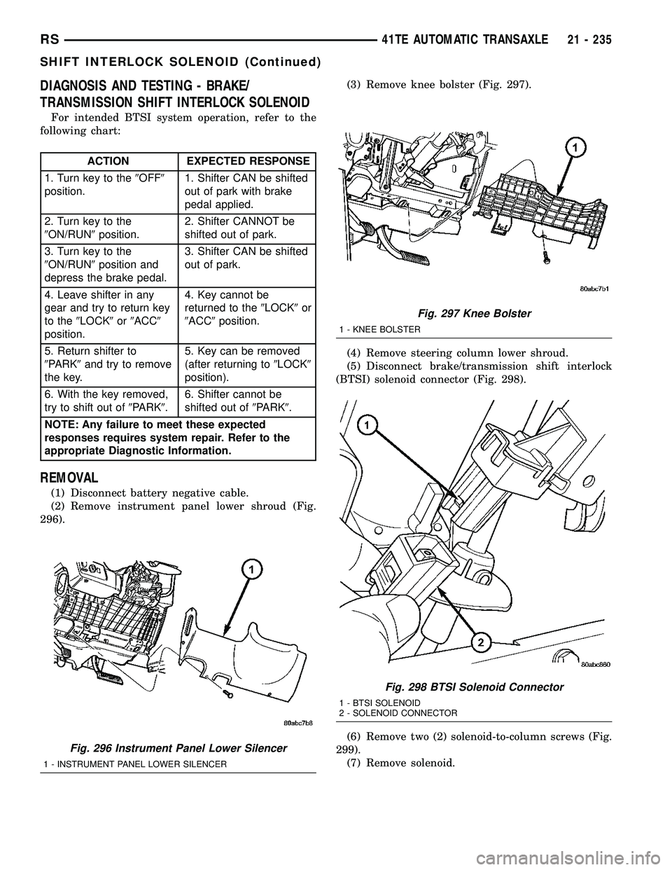
REMOVAL
(1) Disconnect battery negative cable.
(2) Remove instrument panel lower shroud (Fig.
296).(3) Remove knee bolster (Fig. 297).
(4) Remove steering column lower shroud.
(5) Disconnect brake/transmission shift interlock
(BTSI) solenoid connector (Fig. 298).
(6) Remove two (2) solenoid-to-column screws (Fig.
299).
(7) Remove solenoid.
Fig. 296 Instrument Panel Lower Silencer
1 - INSTRUMENT PANEL LOWER SILENCER
Fig. 297 Knee Bolster
1 - KNEE BOLSTER
Fig. 298 BTSI Solenoid Connector
1 - BTSI SOLENOID
2 - SOLENOID CONNECTOR
RS41TE AUTOMATIC TRANSAXLE21 - 235
SHIFT INTERLOCK SOLENOID (Continued)
Page 1885 of 2585
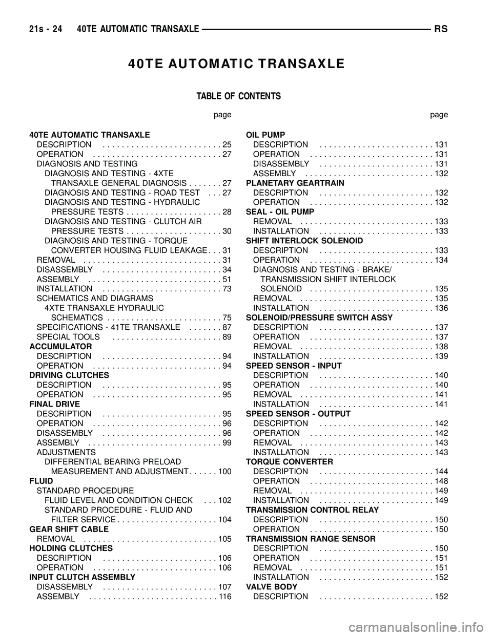
40TE AUTOMATIC TRANSAXLE
TABLE OF CONTENTS
page page
40TE AUTOMATIC TRANSAXLE DESCRIPTION .........................25
OPERATION ...........................27
DIAGNOSIS AND TESTING DIAGNOSIS AND TESTING - 4XTETRANSAXLE GENERAL DIAGNOSIS .......27
DIAGNOSIS AND TESTING - ROAD TEST . . . 27
DIAGNOSIS AND TESTING - HYDRAULIC PRESSURE TESTS ....................28
DIAGNOSIS AND TESTING - CLUTCH AIR PRESSURE TESTS ....................30
DIAGNOSIS AND TESTING - TORQUE CONVERTER HOUSING FLUID LEAKAGE . . . 31
REMOVAL .............................31
DISASSEMBLY .........................34
ASSEMBLY ............................51
INSTALLATION .........................73
SCHEMATICS AND DIAGRAMS 4XTE TRANSAXLE HYDRAULICSCHEMATICS ........................75
SPECIFICATIONS - 41TE TRANSAXLE .......87
SPECIAL TOOLS .......................89
ACCUMULATOR DESCRIPTION .........................94
OPERATION ...........................94
DRIVING CLUTCHES DESCRIPTION .........................95
OPERATION ...........................95
FINAL DRIVE DESCRIPTION .........................95
OPERATION ...........................96
DISASSEMBLY .........................96
ASSEMBLY ............................99
ADJUSTMENTS DIFFERENTIAL BEARING PRELOADMEASUREMENT AND ADJUSTMENT ......100
FLUID STANDARD PROCEDURE FLUID LEVEL AND CONDITION CHECK . . . 102
STANDARD PROCEDURE - FLUID ANDFILTER SERVICE .....................104
GEAR SHIFT CABLE REMOVAL ............................105
HOLDING CLUTCHES DESCRIPTION ........................106
OPERATION ..........................106
INPUT CLUTCH ASSEMBLY DISASSEMBLY ........................107
ASSEMBLY ...........................116 OIL PUMP
DESCRIPTION ........................131
OPERATION ..........................131
DISASSEMBLY ........................131
ASSEMBLY ...........................132
PLANETARY GEARTRAIN DESCRIPTION ........................132
OPERATION ..........................132
SEAL - OIL PUMP REMOVAL ............................133
INSTALLATION ........................133
SHIFT INTERLOCK SOLENOID DESCRIPTION ........................133
OPERATION ..........................134
DIAGNOSIS AND TESTING - BRAKE/ TRANSMISSION SHIFT INTERLOCK
SOLENOID ..........................135
REMOVAL ............................135
INSTALLATION ........................136
SOLENOID/PRESSURE SWITCH ASSY DESCRIPTION ........................137
OPERATION ..........................137
REMOVAL ............................138
INSTALLATION ........................139
SPEED SENSOR - INPUT DESCRIPTION ........................140
OPERATION ..........................140
REMOVAL ............................141
INSTALLATION ........................141
SPEED SENSOR - OUTPUT DESCRIPTION ........................142
OPERATION ..........................142
REMOVAL ............................143
INSTALLATION ........................143
TORQUE CONVERTER DESCRIPTION ........................144
OPERATION ..........................148
REMOVAL ............................149
INSTALLATION ........................149
TRANSMISSION CONTROL RELAY DESCRIPTION ........................150
OPERATION ..........................150
TRANSMISSION RANGE SENSOR DESCRIPTION ........................150
OPERATION ..........................151
REMOVAL ............................151
INSTALLATION ........................152
VALVE BODY DESCRIPTION ........................152
21s - 24 40TE AUTOMATIC TRANSAXLERS
Page 1890 of 2585
TEST FIVE-SELECTOR IN OVERDRIVE (4th Gear-CC
on)
(1) Attach gauge to the torque converter clutch off
pressure tap. (2) Move selector lever to the (OD) position.
(3) Allow vehicle wheels to turn and increase
throttle opening to achieve an indicated vehicle speed
of 50 mph. Vehicle should be in 4th gear, CC on.
CAUTION: Both wheels must turn at the same
speed.
(4) Torque converter clutch off pressure should be
less than 5 psi. (5) This test checks the torque converter clutch
hydraulic circuit.
TEST SIX-SELECTOR IN REVERSE
(1) Attach gauges to the reverse and LR clutch
tap. (2) Move selector lever to the (R) position.
(3) Read reverse clutch pressure with output sta-
tionary (foot on brake) and throttle opened to achieve
1500 rpm. (4) Reverse and LR clutch pressure should read
165 to 235 psi. (5) This test checks the reverse clutch hydraulic
circuit.
TEST RESULT INDICATIONS
(1) If proper line pressure is found in any one test,
the pump and pressure regulator are working prop-
erly. (2) Low pressure in all positions indicates a defec-
tive pump, a clogged filter, or a stuck pressure regu-
lator valve. (3) Clutch circuit leaks are indicated if pressures
do not fall within the specified pressure range. (4) If the overdrive clutch pressure is greater than
5 psi in Step 4 of Test Three, a worn reaction shaft
seal ring or a defective solenoid assembly is indi-
cated. (5) If the underdrive clutch pressure is greater
than 5 psi in Step 4 of Test Two A, a defective sole-
noid assembly or PCM/TCM is the cause.
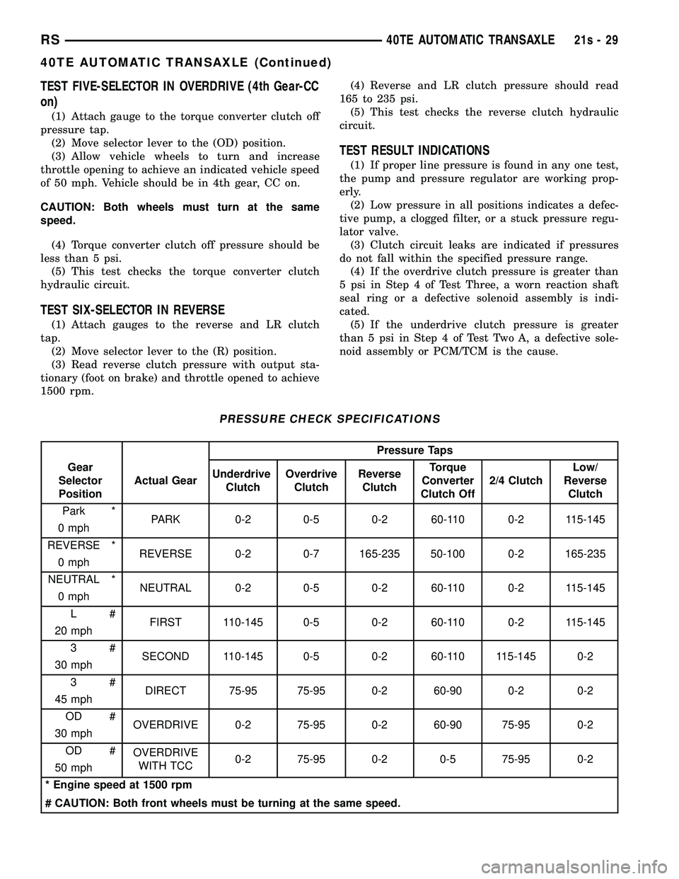
PRESSURE CHECK SPECIFICATIONS
Pressure Taps
Gear
Selector
Position Actual Gear
Underdrive
Clutch Overdrive
Clutch Reverse
Clutch Torque
Converter
Clutch Off 2/4 Clutch Low/
Reverse Clutch
Park * PARK 0-2 0-5 0-2 60-110 0-2 115-145
0 mph
REVERSE * REVERSE 0-2 0-7 165-235 50-100 0-2 165-235
0 mph
NEUTRAL * NEUTRAL 0-2 0-5 0-2 60-110 0-2 115-145
0 mph
L# FIRST 110-145 0-5 0-2 60-110 0-2 115-145
20 mph
3# SECOND 110-145 0-5 0-2 60-110 115-145 0-2
30 mph
3# DIRECT 75-95 75-95 0-2 60-90 0-2 0-2
45 mph
OD # OVERDRIVE 0-2 75-95 0-2 60-90 75-95 0-2
30 mph
OD # OVERDRIVE
WITH TCC 0-2 75-95 0-2 0-5 75-95 0-2
50 mph
* Engine speed at 1500 rpm
# CAUTION: Both front wheels must be turning at the same speed.
RS 40TE AUTOMATIC TRANSAXLE21s-29
40TE AUTOMATIC TRANSAXLE (Continued)
Page 1963 of 2585
PRELOAD ADJUSTMENT W/O SHIM(1) Remove the bearing cup from the differential
bearing retainer using Miller special Tool 6062A. (2) Remove existing shim from under bearing cup.
(3) Reinstall the bearing cup into the retainer
using Miller Special Tool 6061, and C-4171.
NOTE: Oil baffle is not required when making the
shim calculation.
(4) Install the bearing retainer into the case.
Torque bolts to 28 N ²m (250 in. lbs.).
(5) Position the transaxle assembly vertically on
the support stand and install Miller Special Tool
L-4436-A into the bearing retainer. (6) Rotate the differential at least one full revolu-
tion to ensure the tapered roller bearings are fully
seated. (7) Attach a dial indicator to the case and zero the
dial. Place the tip on the end of Special Tool
L-4436-A. (8) Place a large screwdriver to each side of the
ring gear and lift. Check the dial indicator for the
amount of end play.
CAUTION: Do not damage the transaxle case and/or
differential retainer sealing surface.
(9) Using the end play measurement that was
determined, add 0.18mm (0.007 inch). This should
give you between 5 and 18 inch pounds of bearing
preload. Refer to the Differential Bearing Shim Chart
to determine which shim to use. (10) Remove the differential bearing retainer.
Remove the bearing cup. (11) Install the oil baffle. Install the proper shim
combination under the bearing cup. (12) Install the differential bearing retainer. Seal
the retainer to the housing with Mopar tSilicone
Rubber Adhesive Sealant. Torque bolts to 28 N ²m
(250 in. lbs.). (13) Using Miller Special Tool L-4436-A and an
inch-pound torque wrench, check the turning torque
of the differential (Fig. 186). The turning torque
should be between 5-18 inch-pounds.
NOTE: If turning torque is too high install a 0.05mm
(0.002 inch) thicker shim. If the turning torque is too
low, install a 0.05mm (0.002 inch) thinner shim.
Repeat until 5-18 inch-pounds of turning torque is
obtained.FLUID
STANDARD PROCEDURE
FLUID LEVEL AND CONDITION CHECK
NOTE: Only transmission fluid of the type labeled
Mopar ATF+4 (Automatic Transmission Fluid)
should be used in this transaxle.
FLUID LEVEL CHECK
The transmission sump has a fluid level indicator
(dipstick) to check oil similar to most automatic
transmissions. It is located on the left side of the
engine. Be sure to wipe all dirt from dipstick handle
before removing. The torque converter fills in both the P Park and N
Neutral positions. Place the selector lever in P Park
to be sure that the fluid level check is accurate. The
engine should be running at idle speed for at
least one minute, with the vehicle on level
ground. At normal operating temperature 82É C
(180É F), the fluid level is correct if it is in the HOT
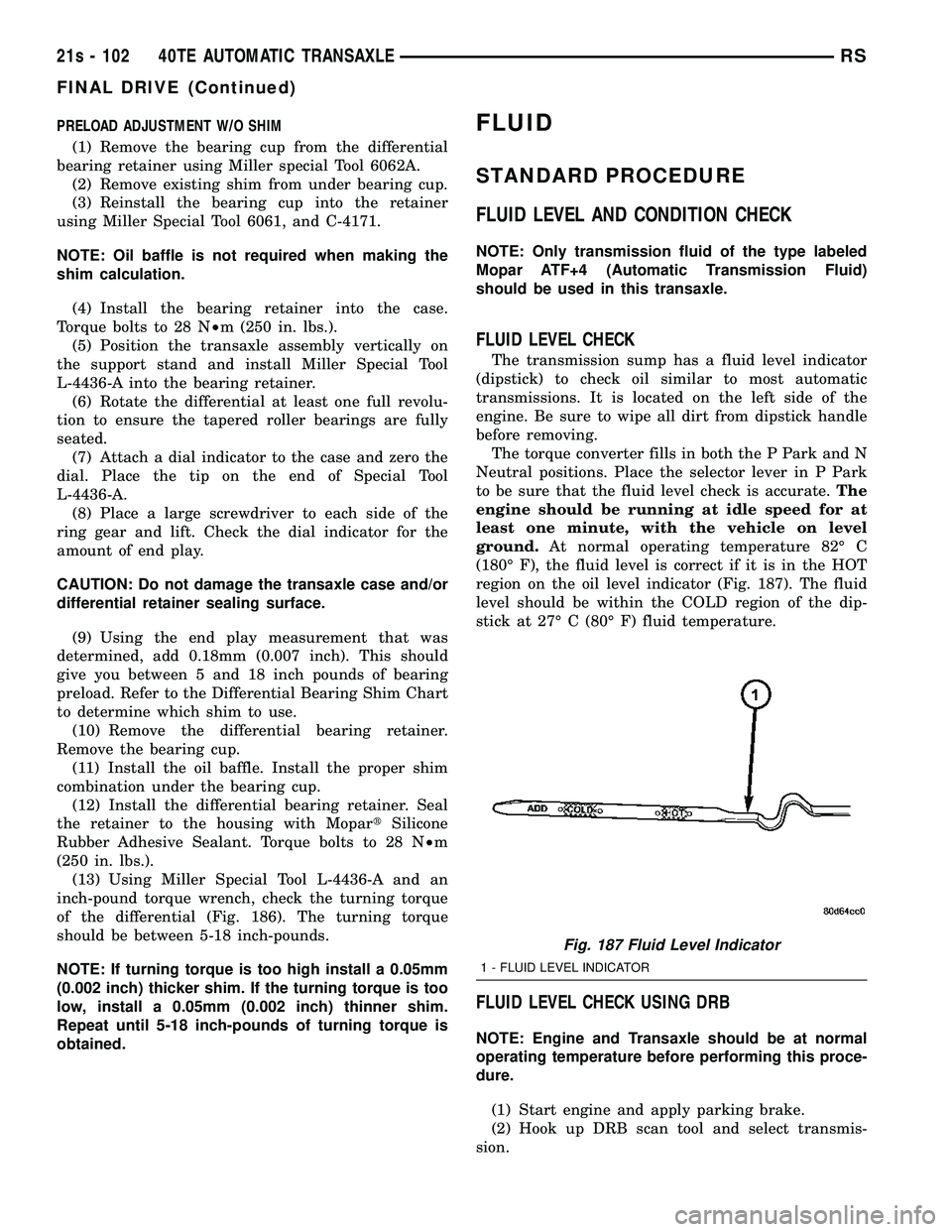
region on the oil level indicator (Fig. 187). The fluid
level should be within the COLD region of the dip-
stick at 27É C (80É F) fluid temperature.
FLUID LEVEL CHECK USING DRB
NOTE: Engine and Transaxle should be at normal
operating temperature before performing this proce-
dure.
(1) Start engine and apply parking brake.
(2) Hook up DRB scan tool and select transmis-
sion.
Fig. 187 Fluid Level Indicator
1 - FLUID LEVEL INDICATOR
21s - 102 40TE AUTOMATIC TRANSAXLERS
FINAL DRIVE (Continued)
Page 1965 of 2585

STANDARD PROCEDURE - FLUID AND FILTER
SERVICE
NOTE: Refer to the maintenance schedules in
LUBRICATION and MAINTENANCE, or the vehicle
owner's manual, for the recommended maintenance
(fluid/filter change) intervals for this transaxle.
NOTE: Only fluids of the type labeled MoparTATF+4
should be used. A filter change should be made at
the time of the transmission oil change. The magnet
(on the inside of the oil pan) should also be cleaned
with a clean, dry cloth.
NOTE: If the transaxle is disassembled for any rea-
son, the fluid and filter should be changed.
FLUID/FILTER SERVICE (RECOMMENDED)
(1) Raise vehicle on a hoist. Refer to LUBRICA-
TION and MAINTENANCE for proper procedures.
Place a drain container with a large opening, under
transaxle oil pan. (2) Remove both engine mount-to-engine cross-
member cradle nuts. Using suitable screw jack and
wood block, raise engine and transmission slightly to
facilitate transaxle oil pan removal and installation. (3) Loosen pan bolts and tap the pan at one corner
to break it loose allowing fluid to drain, then remove
the oil pan. (4) Install a new filter and o-ring on bottom of the
valve body (Fig. 189). (5) Clean the oil pan and magnet. Reinstall pan
using new Mopar Silicone Adhesive sealant. Tighten
oil pan bolts to 19 N´m (165 in. lbs.). (6) Pour four quarts of Mopar tATF+4 through the
dipstick opening. (7) Start engine and allow to idle for at least one
minute. Then, with parking and service brakes
applied, move selector lever momentarily to each
position, ending in the park or neutral position. (8) Check the transaxle fluid level and add an
appropriate amount to bring the transaxle fluid level
to 3mm (1/8 in.) below the lowest mark on the dip-
stick (Fig. 190).
(9) Recheck the fluid level after the transaxle has
reached normal operating temperature (180ÉF.). Refer
to Fluid Level and Condition Check for the proper
fluid fill procedure. (10) To prevent dirt from entering transaxle, make
certain that dipstick is fully seated into the dipstick
opening.
DIPSTICK TUBE FLUID SUCTION METHOD
(ALTERNATIVE)
(1) When performing the fluid suction method,
make sure the transaxle is at full operating temper-
ature. (2) To perform the dipstick tube fluid suction
method, use a suitable fluid suction device (VaculaŸ
or equivalent). (3) Insert the fluid suction line into the dipstick
tube.
NOTE: Verify that the suction line is inserted to the
lowest point of the transaxle oil pan. This will
ensure complete evacuation of the fluid in the pan.
(4) Follow the manufacturers recommended proce-
dure and evacuate the fluid from the transaxle.
Fig. 189 Filter and O-Ring
1 - OIL FILTER
2 - O-RING
Fig. 190 Fluid Level Indicator
1 - FLUID LEVEL INDICATOR
21s - 104 40TE AUTOMATIC TRANSAXLERS
FLUID (Continued)
Page 1966 of 2585
(5) Remove the suction line from the dipstick tube.
(6) Pour four quarts of MopartATF+4 through the
dipstick opening. (7) Start engine and allow to idle for at least one
minute. Then, with parking and service brakes
applied, move selector lever momentarily to each
position, ending in the park or neutral position. (8) Check the transaxle fluid level and add an
appropriate amount to bring the transaxle fluid level
to 3mm (1/8 in.) below the lowest mark on the dip-
stick (Fig. 190). (9) Recheck the fluid level after the transaxle has
reached normal operating temperature (180ÉF.).
(Refer to 21 - TRANSMISSION/TRANSAXLE/AUTO-
MATIC - 41TE/FLUID - STANDARD PROCEDURE) (10) To prevent dirt from entering transaxle, make
certain that dipstick is fully seated into the dipstick
opening.
GEAR SHIFT CABLE
REMOVAL
(1) Disconnect battery cables.
(2) Remove battery shield.
(3) Remove battery.
(4) Remove speed control servo and position out of
way. (5) Disconnect gear shift cable at manual valve
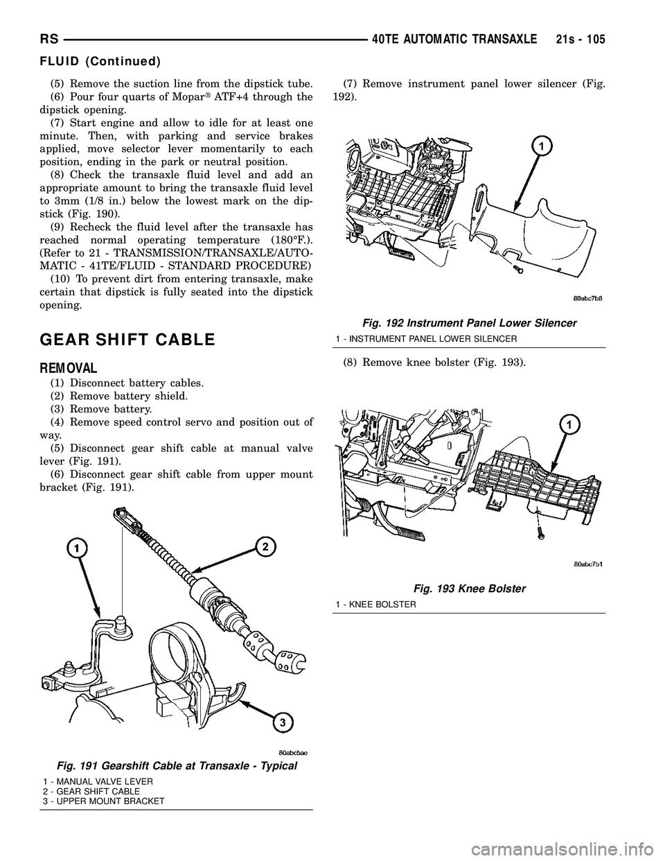
lever (Fig. 191). (6) Disconnect gear shift cable from upper mount
bracket (Fig. 191). (7) Remove instrument panel lower silencer (Fig.
192).
(8) Remove knee bolster (Fig. 193).
Fig. 191 Gearshift Cable at Transaxle - Typical
1 - MANUAL VALVE LEVER
2 - GEAR SHIFT CABLE
3 - UPPER MOUNT BRACKET
Fig. 192 Instrument Panel Lower Silencer
1 - INSTRUMENT PANEL LOWER SILENCER
Fig. 193 Knee Bolster
1 - KNEE BOLSTER
RS 40TE AUTOMATIC TRANSAXLE21s - 105
FLUID (Continued)
Page 1994 of 2585
SEAL - OIL PUMP
REMOVAL
(1) Remove transaxle from vehicle (Refer to 21 -
TRANSMISSION/TRANSAXLE/AUTOMATIC - 41TE
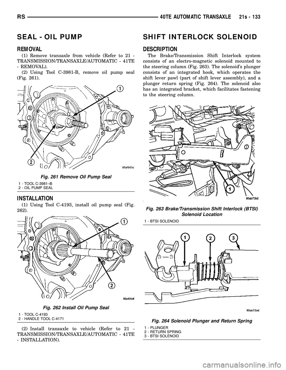
- REMOVAL). (2) Using Tool C-3981-B, remove oil pump seal
(Fig. 261).
INSTALLATION
(1) Using Tool C-4193, install oil pump seal (Fig.
262).
(2) Install transaxle to vehicle (Refer to 21 -
TRANSMISSION/TRANSAXLE/AUTOMATIC - 41TE
- INSTALLATION).
SHIFT INTERLOCK SOLENOID
DESCRIPTION
The Brake/Transmission Shift Interlock system
consists of an electro-magnetic solenoid mounted to
the steering column (Fig. 263). The solenoid's plunger
consists of an integrated hook, which operates the
shift lever pawl (part of shift lever assembly), and a
plunger return spring (Fig. 264). The solenoid also
has an integrated bracket, which facilitates fastening
to the steering column.
Fig. 261 Remove Oil Pump Seal
1 - TOOL C-3981±B
2 - OIL PUMP SEAL
Fig. 262 Install Oil Pump Seal
1 - TOOL C-4193
2 - HANDLE TOOL C-4171
Fig. 263 Brake/Transmission Shift Interlock (BTSI) Solenoid Location
1 - BTSI SOLENOID
Fig. 264 Solenoid Plunger and Return Spring
1 - PLUNGER
2 - RETURN SPRING
3 - BTSI SOLENOID
RS 40TE AUTOMATIC TRANSAXLE21s - 133