2004 CHRYSLER VOYAGER brake
[x] Cancel search: brakePage 2106 of 2585
TIRES
TABLE OF CONTENTS
page page
TIRES DESCRIPTION DESCRIPTION - TIRE ...................5
DESCRIPTION - RADIAL-PLY TIRES ........6
DESCRIPTION - REPLACEMENT TIRES .....6
DESCRIPTION - SPARE TIRE (TEMPORARY) ........................6
DIAGNOSIS AND TESTING DIAGNOSIS AND TESTING - TIRE NOISE ....6
DIAGNOSIS AND TESTING - TIRE/VEHICLE LEAD ................................6
DIAGNOSIS AND TESTING - TIRE WEAR PATTERNS ...........................8 DIAGNOSIS AND TESTING - TREAD WEAR
INDICATORS ..........................8
STANDARD PROCEDURE STANDARD PROCEDURE - TIRE INFLATIONPRESSURES ..........................8
STANDARD PROCEDURE - TIRE PRESSURE FOR HIGH SPEED
OPERATION ..........................9
STANDARD PROCEDURE - TIRE LEAK REPAIRING ...........................9
CLEANING - TIRES .....................10
TIRES
DESCRIPTION
DESCRIPTION - TIRE
Tires are designed and engineered for each specific
vehicle. They provide the best overall performance
for normal operation. The ride and handling charac-
teristics match the vehicle's requirements. With
proper care they will give excellent reliability, trac-
tion, skid resistance, and tread life. Driving habits have more effect on tire life than
any other factor. Careful drivers will obtain, in most
cases, much greater mileage than severe use or care-
less drivers. A few of the driving habits which will
shorten the life of any tire are: ² Rapid acceleration
² Severe application of brakes
² High-speed driving
² Taking turns at excessive speeds
² Striking curbs and other obstacles
² Operating vehicle with over or under inflated
tire pressures Radial ply tires are more prone to irregular tread
wear. It is important to follow the tire rotation inter-
val shown in the section on Tire Rotation. This will
help to achieve a greater tread-life potential.
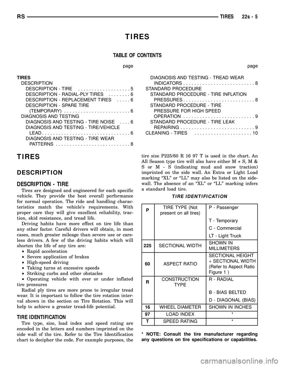
TIRE IDENTIFICATION
Tire type, size, load index and speed rating are
encoded in the letters and numbers imprinted on the
side wall of the tire. Refer to the Tire Identification
chart to decipher the code. For example purposes, the tire size P225/60 R 16 97 T is used in the chart. An
All Season type tire will also have eithe
rM+S,M&
SorM-S (indicating mud and snow traction)
imprinted on the side wall. An Extra or Light Load
marking ªXLº or ªLLº may also be listed on the side-
wall. The absence of an ªXLº or ªLLº marking infers
a standard load tire.
TIRE IDENTIFICATION
P TIRE TYPE (Not
present on all tires) P - Passenger
T - Temporary
C - Commercial
LT - Light Truck
225 SECTIONAL WIDTH SHOWN IN
MILLIMETERS
60 ASPECT RATIO SECTIONAL HEIGHT
÷ SECTIONAL WIDTH
(Refer to Aspect Ratio
Figure 1 )
R CONSTRUCTION
TYPE R - RADIAL
B - BIAS BELTED
D - DIAGONAL (BIAS)
16 WHEEL DIAMETER SHOWN IN INCHES
97 LOAD INDEX *
T SPEED RATING *
* NOTE: Consult the tire manufacturer regarding
any questions on tire specifications or capabilities.
RS TIRES22s-5
Page 2124 of 2585
(5) Wipe all lubricant from exterior of lock cylinder
and key.
ALL OTHER BODY MECHANISMS
(1) Clean component as described above.
(2) Apply specified lubricant to all pivoting and
sliding contact areas of component.
LUBRICANT USAGE
ENGINE OIL
²Door Hinges ± Hinge Pin and Pivot Contact
Areas
²Hood Hinges ± Pivot Points
²Liftgate Hinges
MOPARTSPRAY WHITE LUBE OR EQUIVALENT
²Door Check Straps
²Liftgate Latches²Liftgate Prop Pivots
²Ash Receiver
²Fuel Filler Door Remote Control Latch Mecha-
nism
²Parking Brake Mechanism
²Sliding Seat Tracks
²Liftgate Latch
MOPARTMultipurpose GREASE OR EQUIVALENT
²All Other Hood Mechanisms
MOPARTLOCK CYLINDER LUBRICANT OR
EQUIVALENT
²Door Lock Cylinders
²Liftgate Lock Cylinder
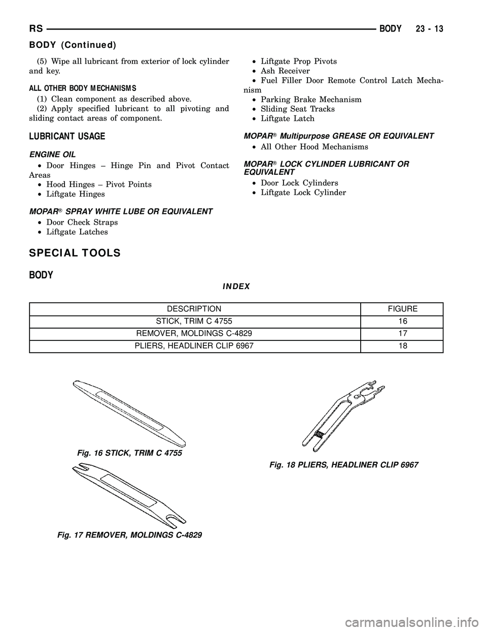
SPECIAL TOOLS
BODY
INDEX
DESCRIPTION FIGURE
STICK, TRIM C 4755 16
REMOVER, MOLDINGS C-4829 17
PLIERS, HEADLINER CLIP 6967 18
Fig. 16 STICK, TRIM C 4755
Fig. 17 REMOVER, MOLDINGS C-4829
Fig. 18 PLIERS, HEADLINER CLIP 6967
RSBODY23-13
BODY (Continued)
Page 2173 of 2585
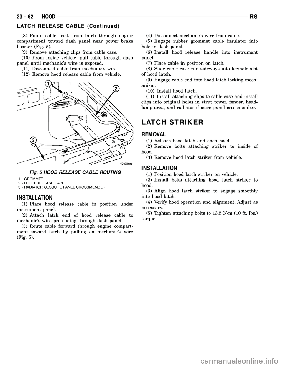
(8) Route cable back from latch through engine
compartment toward dash panel near power brake
booster (Fig. 5).
(9) Remove attaching clips from cable case.
(10) From inside vehicle, pull cable through dash
panel until mechanic's wire is exposed.
(11) Disconnect cable from mechanic's wire.
(12) Remove hood release cable from vehicle.
INSTALLATION
(1) Place hood release cable in position under
instrument panel.
(2) Attach latch end of hood release cable to
mechanic's wire protruding through dash panel.
(3) Route cable forward through engine compart-
ment toward latch by pulling on mechanic's wire
(Fig. 5).(4) Disconnect mechanic's wire from cable.
(5) Engage rubber grommet cable insulator into
hole in dash panel.
(6) Install hood release handle into instrument
panel.
(7) Place cable in position on latch.
(8) Slide cable case end sideways into keyhole slot
of hood latch.
(9) Engage cable end into hood latch locking mech-
anism.
(10) Install hood latch.
(11) Install attaching clips to cable case and install
clips into original holes in strut tower, fender, head-
lamp area, and radiator closure panel crossmember.
LATCH STRIKER
REMOVAL
(1) Release hood latch and open hood.
(2) Remove bolts attaching striker to inside of
hood.
(3) Remove hood latch striker from vehicle.
INSTALLATION
(1) Position hood latch striker on vehicle.
(2) Install bolts attaching hood latch striker to
hood.
(3) Align hood latch striker to engage smoothly
into hood latch.
(4) Verify hood operation and alignment. Adjust as
necessary.
(5) Tighten attaching bolts to 13.5 N´m (10 ft. lbs.)
torque.Fig. 5 HOOD RELEASE CABLE ROUTING
1 - GROMMET
2 - HOOD RELEASE CABLE
3 - RADIATOR CLOSURE PANEL CROSSMEMBER
23 - 62 HOODRS
LATCH RELEASE CABLE (Continued)
Page 2176 of 2585
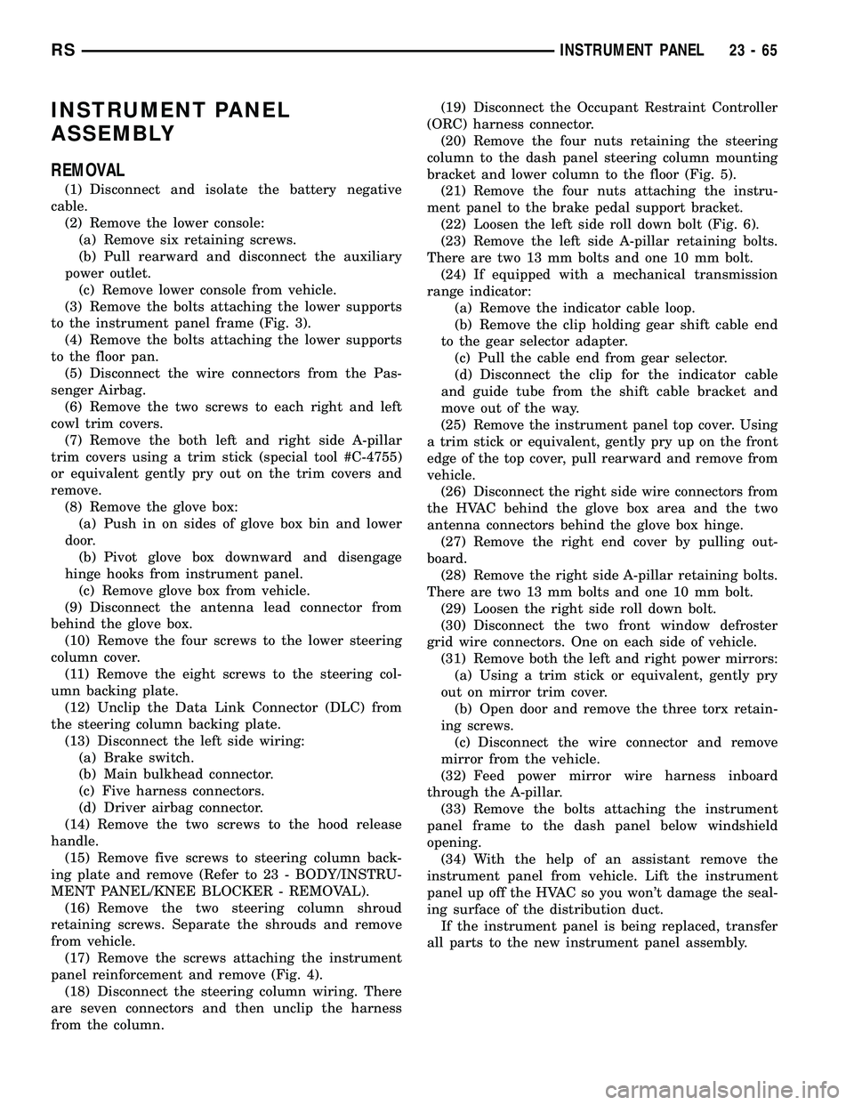
INSTRUMENT PANEL
ASSEMBLY
REMOVAL
(1) Disconnect and isolate the battery negative
cable.
(2) Remove the lower console:
(a) Remove six retaining screws.
(b) Pull rearward and disconnect the auxiliary
power outlet.
(c) Remove lower console from vehicle.
(3) Remove the bolts attaching the lower supports
to the instrument panel frame (Fig. 3).
(4) Remove the bolts attaching the lower supports
to the floor pan.
(5) Disconnect the wire connectors from the Pas-
senger Airbag.
(6) Remove the two screws to each right and left
cowl trim covers.
(7) Remove the both left and right side A-pillar
trim covers using a trim stick (special tool #C-4755)
or equivalent gently pry out on the trim covers and
remove.
(8) Remove the glove box:
(a) Push in on sides of glove box bin and lower
door.
(b) Pivot glove box downward and disengage
hinge hooks from instrument panel.
(c) Remove glove box from vehicle.
(9) Disconnect the antenna lead connector from
behind the glove box.
(10) Remove the four screws to the lower steering
column cover.
(11) Remove the eight screws to the steering col-
umn backing plate.
(12) Unclip the Data Link Connector (DLC) from
the steering column backing plate.
(13) Disconnect the left side wiring:
(a) Brake switch.
(b) Main bulkhead connector.
(c) Five harness connectors.
(d) Driver airbag connector.
(14) Remove the two screws to the hood release
handle.
(15) Remove five screws to steering column back-
ing plate and remove (Refer to 23 - BODY/INSTRU-
MENT PANEL/KNEE BLOCKER - REMOVAL).
(16) Remove the two steering column shroud
retaining screws. Separate the shrouds and remove
from vehicle.
(17) Remove the screws attaching the instrument
panel reinforcement and remove (Fig. 4).
(18) Disconnect the steering column wiring. There
are seven connectors and then unclip the harness
from the column.(19) Disconnect the Occupant Restraint Controller
(ORC) harness connector.
(20) Remove the four nuts retaining the steering
column to the dash panel steering column mounting
bracket and lower column to the floor (Fig. 5).
(21) Remove the four nuts attaching the instru-
ment panel to the brake pedal support bracket.
(22) Loosen the left side roll down bolt (Fig. 6).
(23) Remove the left side A-pillar retaining bolts.
There are two 13 mm bolts and one 10 mm bolt.
(24) If equipped with a mechanical transmission
range indicator:
(a) Remove the indicator cable loop.
(b) Remove the clip holding gear shift cable end
to the gear selector adapter.
(c) Pull the cable end from gear selector.
(d) Disconnect the clip for the indicator cable
and guide tube from the shift cable bracket and
move out of the way.
(25) Remove the instrument panel top cover. Using
a trim stick or equivalent, gently pry up on the front
edge of the top cover, pull rearward and remove from
vehicle.
(26) Disconnect the right side wire connectors from
the HVAC behind the glove box area and the two
antenna connectors behind the glove box hinge.
(27) Remove the right end cover by pulling out-
board.
(28) Remove the right side A-pillar retaining bolts.
There are two 13 mm bolts and one 10 mm bolt.
(29) Loosen the right side roll down bolt.
(30) Disconnect the two front window defroster
grid wire connectors. One on each side of vehicle.
(31) Remove both the left and right power mirrors:
(a) Using a trim stick or equivalent, gently pry
out on mirror trim cover.
(b) Open door and remove the three torx retain-
ing screws.
(c) Disconnect the wire connector and remove
mirror from the vehicle.
(32) Feed power mirror wire harness inboard
through the A-pillar.
(33) Remove the bolts attaching the instrument
panel frame to the dash panel below windshield
opening.
(34) With the help of an assistant remove the
instrument panel from vehicle. Lift the instrument
panel up off the HVAC so you won't damage the seal-
ing surface of the distribution duct.
If the instrument panel is being replaced, transfer
all parts to the new instrument panel assembly.
RSINSTRUMENT PANEL23-65
Page 2177 of 2585
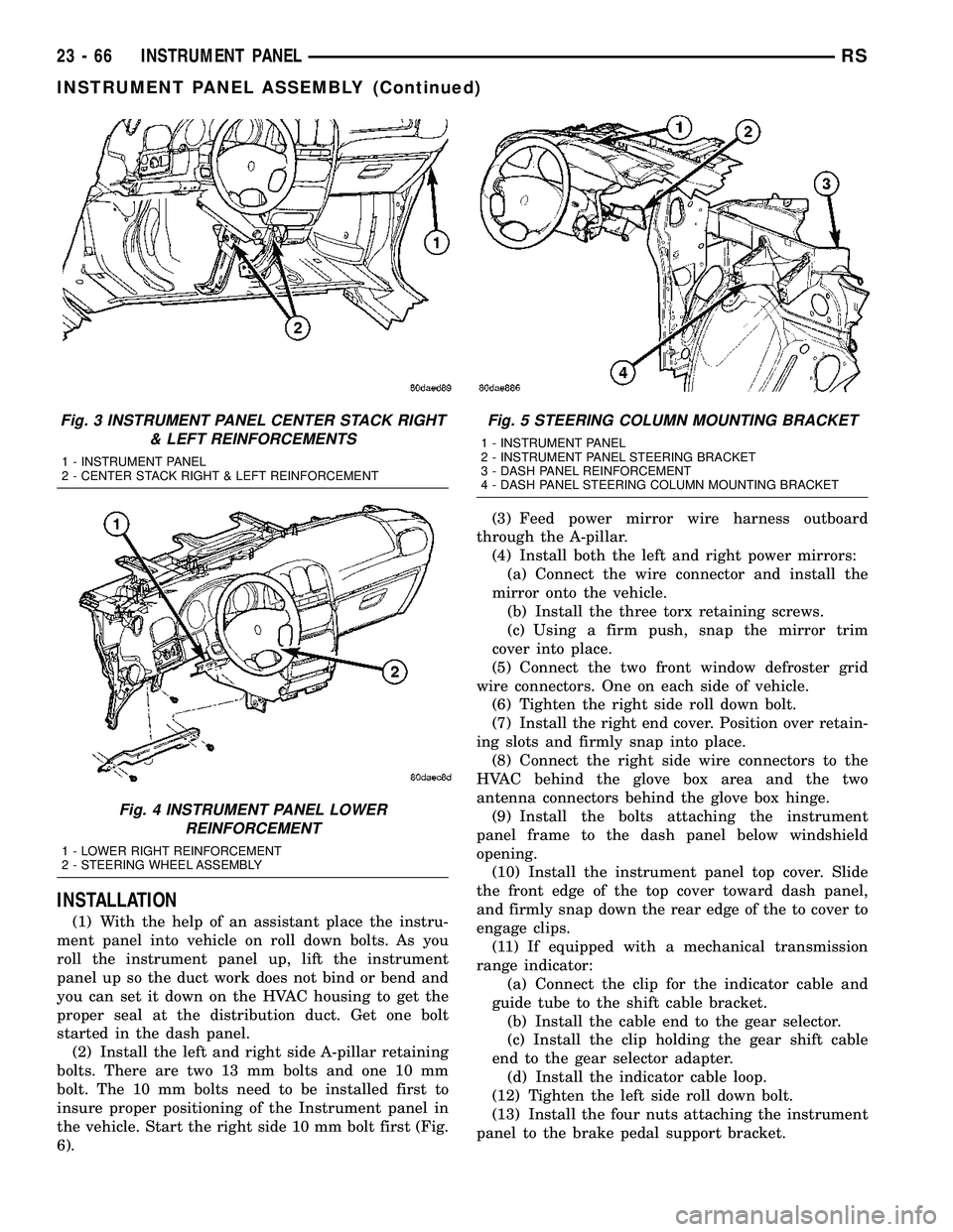
INSTALLATION
(1) With the help of an assistant place the instru-
ment panel into vehicle on roll down bolts. As you
roll the instrument panel up, lift the instrument
panel up so the duct work does not bind or bend and
you can set it down on the HVAC housing to get the
proper seal at the distribution duct. Get one bolt
started in the dash panel.
(2) Install the left and right side A-pillar retaining
bolts. There are two 13 mm bolts and one 10 mm
bolt. The 10 mm bolts need to be installed first to
insure proper positioning of the Instrument panel in
the vehicle. Start the right side 10 mm bolt first (Fig.
6).(3) Feed power mirror wire harness outboard
through the A-pillar.
(4) Install both the left and right power mirrors:
(a) Connect the wire connector and install the
mirror onto the vehicle.
(b) Install the three torx retaining screws.
(c) Using a firm push, snap the mirror trim
cover into place.
(5) Connect the two front window defroster grid
wire connectors. One on each side of vehicle.
(6) Tighten the right side roll down bolt.
(7) Install the right end cover. Position over retain-
ing slots and firmly snap into place.
(8) Connect the right side wire connectors to the
HVAC behind the glove box area and the two
antenna connectors behind the glove box hinge.
(9) Install the bolts attaching the instrument
panel frame to the dash panel below windshield
opening.
(10) Install the instrument panel top cover. Slide
the front edge of the top cover toward dash panel,
and firmly snap down the rear edge of the to cover to
engage clips.
(11) If equipped with a mechanical transmission
range indicator:
(a) Connect the clip for the indicator cable and
guide tube to the shift cable bracket.
(b) Install the cable end to the gear selector.
(c) Install the clip holding the gear shift cable
end to the gear selector adapter.
(d) Install the indicator cable loop.
(12) Tighten the left side roll down bolt.
(13) Install the four nuts attaching the instrument
panel to the brake pedal support bracket.
Fig. 3 INSTRUMENT PANEL CENTER STACK RIGHT
& LEFT REINFORCEMENTS
1 - INSTRUMENT PANEL
2 - CENTER STACK RIGHT & LEFT REINFORCEMENT
Fig. 4 INSTRUMENT PANEL LOWER
REINFORCEMENT
1 - LOWER RIGHT REINFORCEMENT
2 - STEERING WHEEL ASSEMBLY
Fig. 5 STEERING COLUMN MOUNTING BRACKET
1 - INSTRUMENT PANEL
2 - INSTRUMENT PANEL STEERING BRACKET
3 - DASH PANEL REINFORCEMENT
4 - DASH PANEL STEERING COLUMN MOUNTING BRACKET
23 - 66 INSTRUMENT PANELRS
INSTRUMENT PANEL ASSEMBLY (Continued)
Page 2178 of 2585
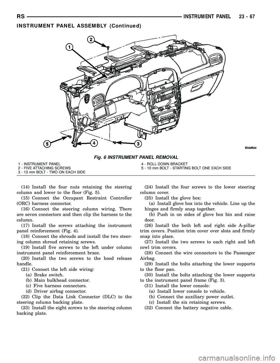
(14) Install the four nuts retaining the steering
column and lower to the floor (Fig. 5).
(15) Connect the Occupant Restraint Controller
(ORC) harness connector.
(16) Connect the steering column wiring. There
are seven connectors and then clip the harness to the
column.
(17) Install the screws attaching the instrument
panel reinforcement (Fig. 4).
(18) Connect the shrouds and install the two steer-
ing column shroud retaining screws.
(19) Install five screws to the left under column
instrument panel reinforcement brace.
(20) Install the two screws to the hood release
handle.
(21) Connect the left side wiring:
(a) Brake switch.
(b) Main bulkhead connector.
(c) Five harness connectors.
(d) Driver airbag connector.
(22) Clip the Data Link Connector (DLC) to the
steering column backing plate.
(23) Install the eight screws to the steering column
backing plate.(24) Install the four screws to the lower steering
column cover.
(25) Install the glove box:
(a) Install glove box into the vehicle. Line up the
hinges and firmly snap together.
(b) Push in on sides of glove box bin and raise
door.
(26) Install the both left and right side A-pillar
trim covers. Position trim cover over slots and firmly
snap into place.
(27) Install the two screws to each right and left
cowl trim covers.
(28) Connect the wire connectors to the Passenger
Airbag.
(29) Install the bolts attaching the lower supports
to the floor pan.
(30) Install the bolts attaching the lower supports
to the instrument panel frame (Fig. 3).
(31) Install the lower console:
(a) Install lower console to vehicle.
(b) Connect the auxiliary power outlet.
(c) Install the six retaining screws.
(32) Connect the battery negative cable.
Fig. 6 INSTRUMENT PANEL REMOVAL
1 - INSTRUMENT PANEL
2 - FIVE ATTACHING SCREWS
3 - 13 mm BOLT - TWO ON EACH SIDE4 - ROLL DOWN BRACKET
5 - 10 mm BOLT - STARTING BOLT ONE EACH SIDE
RSINSTRUMENT PANEL23-67
INSTRUMENT PANEL ASSEMBLY (Continued)
Page 2181 of 2585
(8) Install the center bezel.
(9) Install the lower steering column cover.
(10) Install the right end cover.
LOWER STEERING COLUMN
COVER
REMOVAL
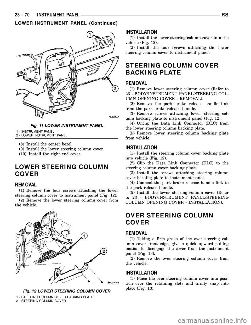
(1) Remove the four screws attaching the lower
steering column cover to instrument panel (Fig. 12).
(2) Remove the lower steering column cover from
the vehicle.
INSTALLATION
(1) Install the lower steering column cover into the
vehicle (Fig. 12).
(2) Install the four screws attaching the lower
steering column cover to instrument panel.
STEERING COLUMN COVER
BACKING PLATE
REMOVAL
(1) Remove lower steering column cover (Refer to
23 - BODY/INSTRUMENT PANEL/STEERING COL-
UMN OPENING COVER - REMOVAL).
(2) Remove the park brake release handle link
from the park brake release handle.
(3) Remove screws attaching lower steering col-
umn backing plate to instrument panel (Fig. 12).
(4) Unclip the Data Link Connector (DLC) from
the lower steering column backing plate.
(5) Remove lower steering column backing plate
from vehicle.
INSTALLATION
(1) Install the steering column cover backing plate
into vehicle (Fig. 12).
(2) Clip the Data Link Connector (DLC) to the
steering column cover backing plate
(3) Install the screws attaching steering column
cover backing plate to instrument panel.
(4) Connect the park brake release handle link to
the park release handle.
(5) Install the lower steering column cover (Refer
to 23 - BODY/INSTRUMENT PANEL/STEERING
COLUMN OPENING COVER - INSTALLATION).
OVER STEERING COLUMN
COVER
REMOVAL
(1) Taking a firm grasp of the over steering col-
umn cover front edge, give a quick upward pulling
motion to disengage the cover from the instrument
panel (Fig. 13).
(2) Remove the over steering column cover from
the vehicle.
INSTALLATION
(1) Place the over steering column cover into posi-
tion over the retaining slots and firmly snap into
place (Fig. 13).
Fig. 11 LOWER INSTRUMENT PANEL
1 - INSTRUMENT PANEL
2 - LOWER INSTRUMENT PANEL
Fig. 12 LOWER STEERING COLUMN COVER
1 - STEERING COLUMN COVER BACKING PLATE
2 - STEERING COLUMN COVER
23 - 70 INSTRUMENT PANELRS
LOWER INSTRUMENT PANEL (Continued)
Page 2280 of 2585
DESCRIPTION FIGURE
LOWER COWL PLENUM, SUPPORT AND DASH PANEL - RIGHT HAND DRIVE 182
STEERING COLUMN REINFORCEMENT, BELT REINFORCEMENT AND DASH PANEL -
RIGHT HAND DRIVE183
INSTRUMENT PANEL TAPPING PLATE AND COWL SIDE PANEL - RIGHT HAND DRIVE 184
DASH PANEL AND BELT REINFORCEMENT - RIGHT HAND DRIVE 185
UPPER SUPPORT, UPPER REINFORCEMENT AND UPPER COWL PLENUM - RIGHT
HAND DRIVE186
UPPER SUPPORT, BRAKE PEDAL BRACKET REINFORCEMENT AND DASH PANEL -
RIGHT HAND DRIVE187
REINFORCEMENT, MOUNTING BRACKETS AND DASH PANEL - RIGHT HAND DRIVE 188
STRUT TOWER, COWL SIDE PANEL - RIGHT HAND DRIVE 189
REINFORCEMENTS, SIDE RAILS, COWL SIDE PANELS AND DASH PANEL - RIGHT
HAND DRIVE190
UPPER COWL PLENUM, GUSSETS, SIDE SHIELDS AND BODY SIDE APERTURE -
RIGHT HAND DRIVE191
SIDE GLASS ANTENNA TAPPING PLATE AND INNER BODY SIDE APERTURE - RIGHT
HAND DRIVE192
RSBODY STRUCTURE23 - 169
WELD LOCATIONS (Continued)