2004 CHRYSLER VOYAGER sensor
[x] Cancel search: sensorPage 1446 of 2585

²Check for cylinder head mounting surface distor-
tion using a straightedge and thickness gauge. (Refer
to 9 - ENGINE/CYLINDER HEAD - INSPECTION)
INSTALLATION - LOWER INTAKE MANIFOLD
(1) Place a bead (approximately 1/4 in. diameter)
of MopartEngine RTV GEN II onto each of thefour
manifold to cylinder head gasket corners (Fig. 122).
(2) Carefully install the new intake manifold gas-
ket (Fig. 121). Tighten end seal retainer screws to 12
N´m (105 in. lbs.).
(3) Install lower intake manifold (Fig. 121). Install
the bolts and torque to 1 N´m (10 in. lbs.). Then
torque bolts to 22 N´m (200 in. lbs.) in sequence
shown in (Fig. 123). Then torque again to 22 N´m
(200 in. lbs.). After intake manifold is in place,
inspect to make sure seals are in place.
(4) Install the fuel injectors and rail assembly.
(Refer to 14 - FUEL SYSTEM/FUEL DELIVERY/
FUEL RAIL - INSTALLATION)
(5) Connect fuel injector electrical harness.
(6) Connect the engine coolant temperature sensor
(Fig. 120).
(7) Connect the heater supply (Fig. 120) and radi-
ator upper hoses to manifold.
(8) Connect the fuel line. (Refer to 14 - FUEL SYS-
TEM/FUEL DELIVERY/QUICK CONNECT FIT-
TING - STANDARD PROCEDURE)(9) Install the upper intake manifold. (Refer to 9 -
ENGINE/MANIFOLDS/INTAKE MANIFOLD -
INSTALLATION)
(10) Connect negative battery cable.
Fig. 120 ECT SENSOR & HEATER SUPPLY
1 - ENGINE COOLANT TEMPERATURE SENSOR
2 - CONNECTOR - ENGINE COOLANT SENSOR
3 - FITTING - HEATER SUPPLY
Fig. 121 INTAKE MANIFOLD - LOWER
1 - INTAKE MANIFOLD - LOWER
2 - BOLT - GASKET END SEAL RETAINER
3 - GASKET
4 - BOLT - LOWER INTAKE MANIFOLD
Fig. 122 Intake Manifold Gasket Sealing
1 - SEALER LOCATIONS
RSENGINE 3.3/3.8L9 - 149
INTAKE MANIFOLD - LOWER (Continued)
Page 1447 of 2585
(11) Fill the cooling system. (Refer to 7 - COOL-
ING - STANDARD PROCEDURE)
EXHAUST MANIFOLD - RIGHT
REMOVAL
(1) Disconnect battery negative cable.
(2) Remove the wiper module. (Refer to 8 - ELEC-
TRICAL/WIPERS/WASHERS/WIPER MODULE -
REMOVAL)
(3) Disconnect spark plug wires.
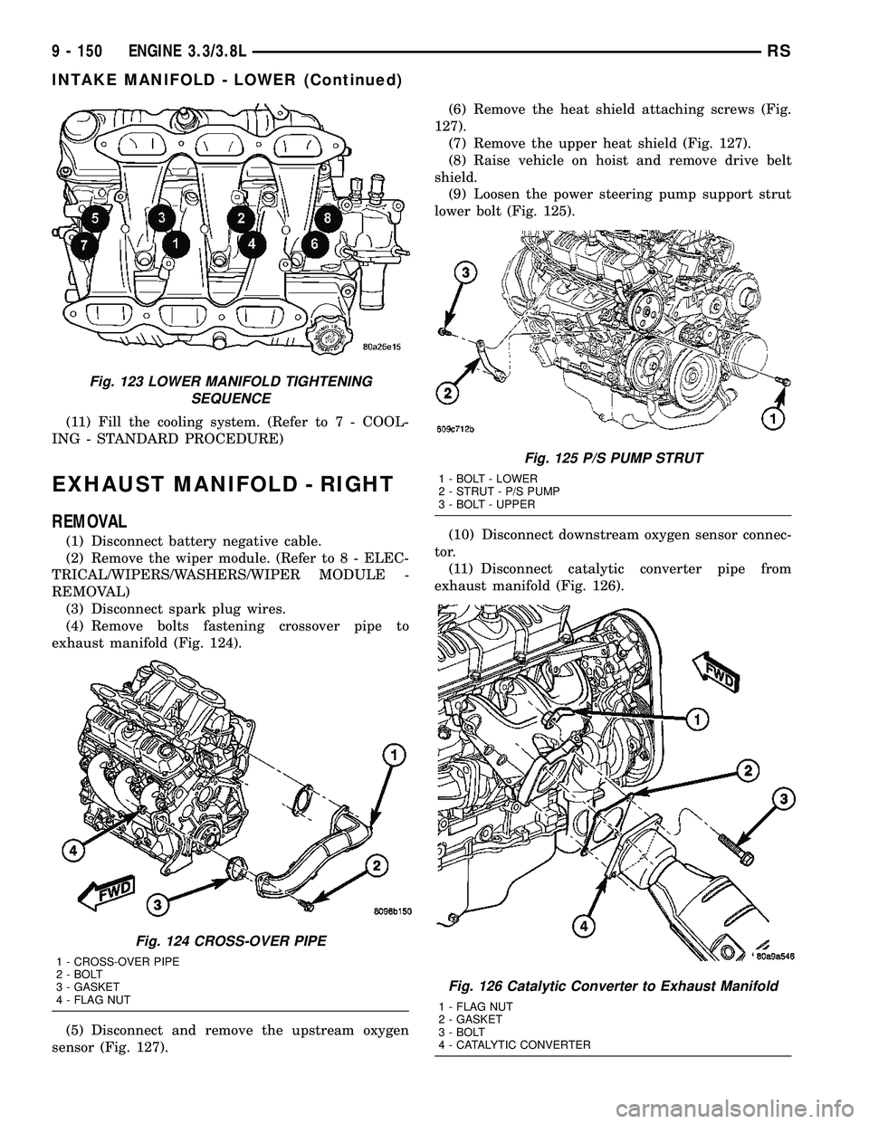
(4) Remove bolts fastening crossover pipe to
exhaust manifold (Fig. 124).
(5) Disconnect and remove the upstream oxygen
sensor (Fig. 127).(6) Remove the heat shield attaching screws (Fig.
127).
(7) Remove the upper heat shield (Fig. 127).
(8) Raise vehicle on hoist and remove drive belt
shield.
(9) Loosen the power steering pump support strut
lower bolt (Fig. 125).
(10) Disconnect downstream oxygen sensor connec-
tor.
(11) Disconnect catalytic converter pipe from
exhaust manifold (Fig. 126).
Fig. 123 LOWER MANIFOLD TIGHTENING
SEQUENCE
Fig. 124 CROSS-OVER PIPE
1 - CROSS-OVER PIPE
2 - BOLT
3 - GASKET
4 - FLAG NUT
Fig. 125 P/S PUMP STRUT
1 - BOLT - LOWER
2 - STRUT - P/S PUMP
3 - BOLT - UPPER
Fig. 126 Catalytic Converter to Exhaust Manifold
1 - FLAG NUT
2 - GASKET
3 - BOLT
4 - CATALYTIC CONVERTER
9 - 150 ENGINE 3.3/3.8LRS
INTAKE MANIFOLD - LOWER (Continued)
Page 1448 of 2585
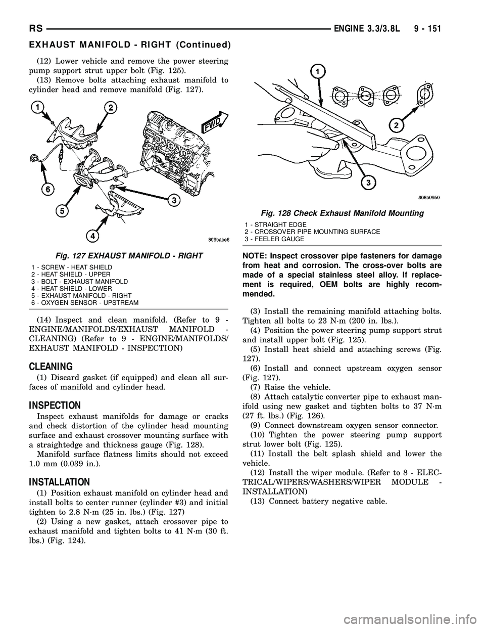
(12) Lower vehicle and remove the power steering
pump support strut upper bolt (Fig. 125).
(13) Remove bolts attaching exhaust manifold to
cylinder head and remove manifold (Fig. 127).
(14) Inspect and clean manifold. (Refer to 9 -
ENGINE/MANIFOLDS/EXHAUST MANIFOLD -
CLEANING) (Refer to 9 - ENGINE/MANIFOLDS/
EXHAUST MANIFOLD - INSPECTION)
CLEANING
(1) Discard gasket (if equipped) and clean all sur-
faces of manifold and cylinder head.
INSPECTION
Inspect exhaust manifolds for damage or cracks
and check distortion of the cylinder head mounting
surface and exhaust crossover mounting surface with
a straightedge and thickness gauge (Fig. 128).
Manifold surface flatness limits should not exceed
1.0 mm (0.039 in.).
INSTALLATION
(1) Position exhaust manifold on cylinder head and
install bolts to center runner (cylinder #3) and initial
tighten to 2.8 N´m (25 in. lbs.) (Fig. 127)
(2) Using a new gasket, attach crossover pipe to
exhaust manifold and tighten bolts to 41 N´m (30 ft.
lbs.) (Fig. 124).NOTE: Inspect crossover pipe fasteners for damage
from heat and corrosion. The cross-over bolts are
made of a special stainless steel alloy. If replace-
ment is required, OEM bolts are highly recom-
mended.
(3) Install the remaining manifold attaching bolts.
Tighten all bolts to 23 N´m (200 in. lbs.).
(4) Position the power steering pump support strut
and install upper bolt (Fig. 125).
(5) Install heat shield and attaching screws (Fig.
127).
(6) Install and connect upstream oxygen sensor
(Fig. 127).
(7) Raise the vehicle.
(8) Attach catalytic converter pipe to exhaust man-
ifold using new gasket and tighten bolts to 37 N´m
(27 ft. lbs.) (Fig. 126).
(9) Connect downstream oxygen sensor connector.
(10) Tighten the power steering pump support
strut lower bolt (Fig. 125).
(11) Install the belt splash shield and lower the
vehicle.
(12) Install the wiper module. (Refer to 8 - ELEC-
TRICAL/WIPERS/WASHERS/WIPER MODULE -
INSTALLATION)
(13) Connect battery negative cable.
Fig. 127 EXHAUST MANIFOLD - RIGHT
1 - SCREW - HEAT SHIELD
2 - HEAT SHIELD - UPPER
3 - BOLT - EXHAUST MANIFOLD
4 - HEAT SHIELD - LOWER
5 - EXHAUST MANIFOLD - RIGHT
6 - OXYGEN SENSOR - UPSTREAM
Fig. 128 Check Exhaust Manifold Mounting
1 - STRAIGHT EDGE
2 - CROSSOVER PIPE MOUNTING SURFACE
3 - FEELER GAUGE
RSENGINE 3.3/3.8L9 - 151
EXHAUST MANIFOLD - RIGHT (Continued)
Page 1451 of 2585
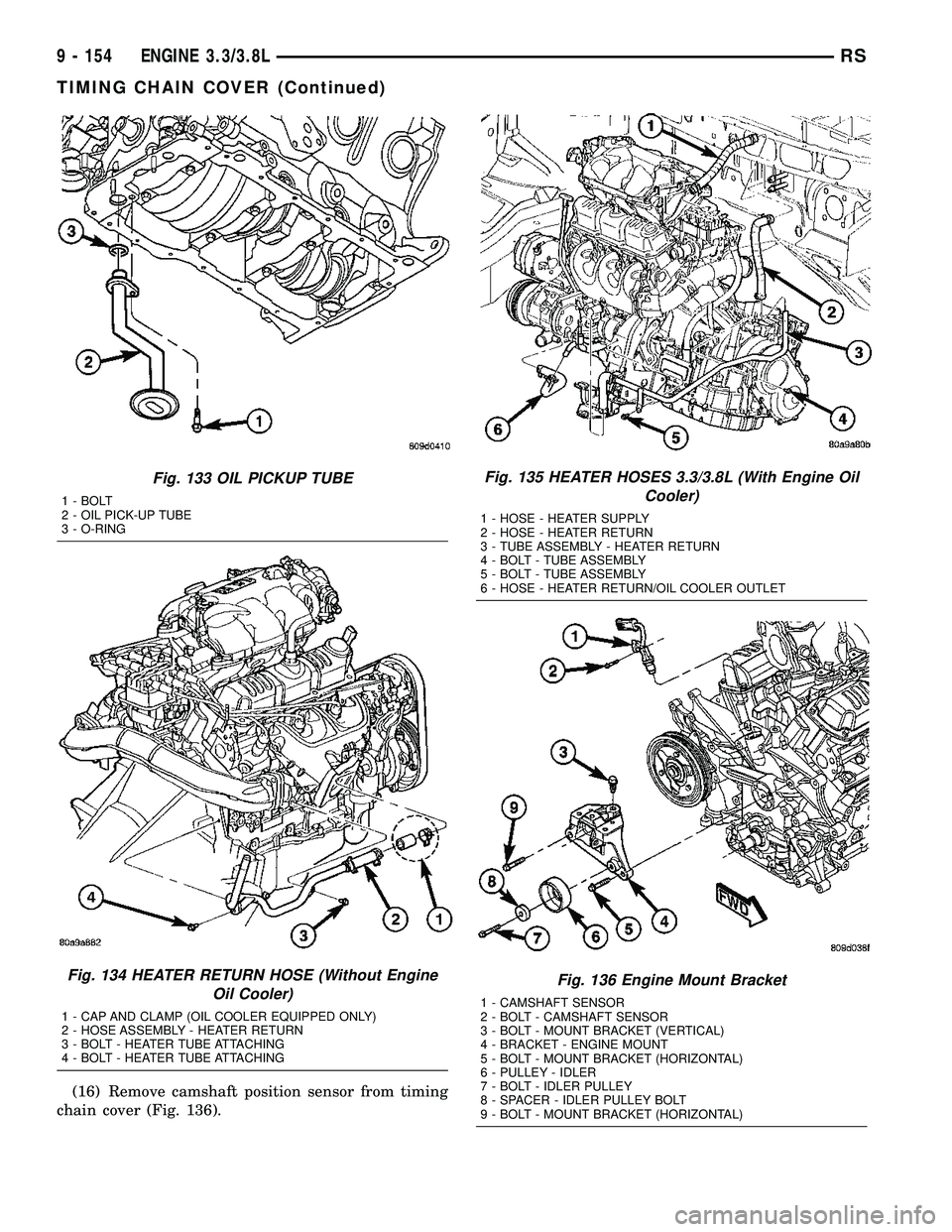
(16) Remove camshaft position sensor from timing
chain cover (Fig. 136).
Fig. 133 OIL PICKUP TUBE
1 - BOLT
2 - OIL PICK-UP TUBE
3 - O-RING
Fig. 134 HEATER RETURN HOSE (Without Engine
Oil Cooler)
1 - CAP AND CLAMP (OIL COOLER EQUIPPED ONLY)
2 - HOSE ASSEMBLY - HEATER RETURN
3 - BOLT - HEATER TUBE ATTACHING
4 - BOLT - HEATER TUBE ATTACHING
Fig. 135 HEATER HOSES 3.3/3.8L (With Engine Oil
Cooler)
1 - HOSE - HEATER SUPPLY
2 - HOSE - HEATER RETURN
3 - TUBE ASSEMBLY - HEATER RETURN
4 - BOLT - TUBE ASSEMBLY
5 - BOLT - TUBE ASSEMBLY
6 - HOSE - HEATER RETURN/OIL COOLER OUTLET
Fig. 136 Engine Mount Bracket
1 - CAMSHAFT SENSOR
2 - BOLT - CAMSHAFT SENSOR
3 - BOLT - MOUNT BRACKET (VERTICAL)
4 - BRACKET - ENGINE MOUNT
5 - BOLT - MOUNT BRACKET (HORIZONTAL)
6 - PULLEY - IDLER
7 - BOLT - IDLER PULLEY
8 - SPACER - IDLER PULLEY BOLT
9 - BOLT - MOUNT BRACKET (HORIZONTAL)
9 - 154 ENGINE 3.3/3.8LRS
TIMING CHAIN COVER (Continued)
Page 1452 of 2585
(17) Remove the water pump for cover removal
clearance. (Refer to 7 - COOLING/ENGINE/WATER
PUMP - REMOVAL)
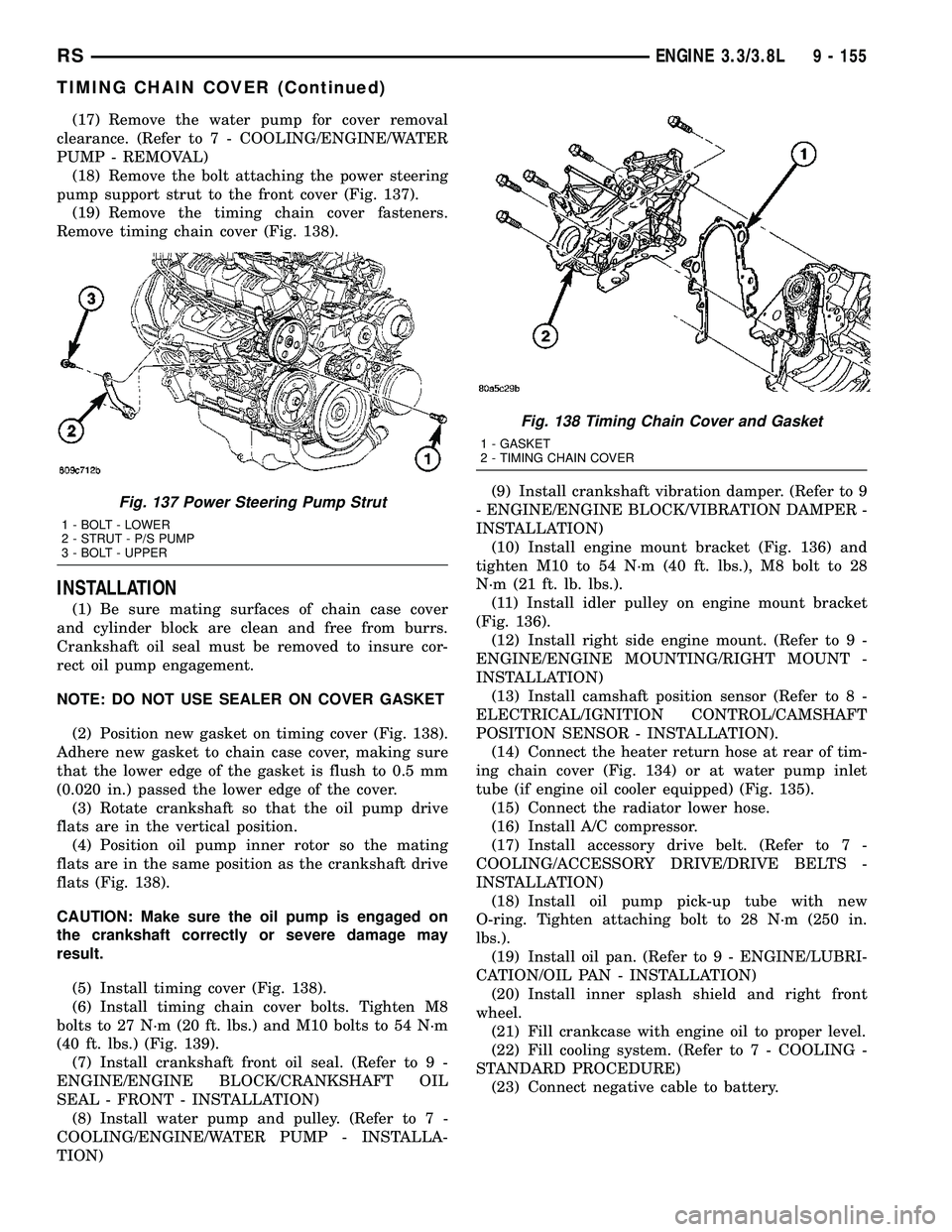
(18) Remove the bolt attaching the power steering
pump support strut to the front cover (Fig. 137).
(19) Remove the timing chain cover fasteners.
Remove timing chain cover (Fig. 138).
INSTALLATION
(1) Be sure mating surfaces of chain case cover
and cylinder block are clean and free from burrs.
Crankshaft oil seal must be removed to insure cor-
rect oil pump engagement.
NOTE: DO NOT USE SEALER ON COVER GASKET
(2) Position new gasket on timing cover (Fig. 138).
Adhere new gasket to chain case cover, making sure
that the lower edge of the gasket is flush to 0.5 mm
(0.020 in.) passed the lower edge of the cover.
(3) Rotate crankshaft so that the oil pump drive
flats are in the vertical position.
(4) Position oil pump inner rotor so the mating
flats are in the same position as the crankshaft drive
flats (Fig. 138).
CAUTION: Make sure the oil pump is engaged on
the crankshaft correctly or severe damage may
result.
(5) Install timing cover (Fig. 138).
(6) Install timing chain cover bolts. Tighten M8
bolts to 27 N´m (20 ft. lbs.) and M10 bolts to 54 N´m
(40 ft. lbs.) (Fig. 139).
(7) Install crankshaft front oil seal. (Refer to 9 -
ENGINE/ENGINE BLOCK/CRANKSHAFT OIL
SEAL - FRONT - INSTALLATION)
(8) Install water pump and pulley. (Refer to 7 -
COOLING/ENGINE/WATER PUMP - INSTALLA-
TION)(9) Install crankshaft vibration damper. (Refer to 9
- ENGINE/ENGINE BLOCK/VIBRATION DAMPER -
INSTALLATION)
(10) Install engine mount bracket (Fig. 136) and
tighten M10 to 54 N´m (40 ft. lbs.), M8 bolt to 28
N´m (21 ft. lb. lbs.).
(11) Install idler pulley on engine mount bracket
(Fig. 136).
(12) Install right side engine mount. (Refer to 9 -
ENGINE/ENGINE MOUNTING/RIGHT MOUNT -
INSTALLATION)
(13) Install camshaft position sensor (Refer to 8 -
ELECTRICAL/IGNITION CONTROL/CAMSHAFT
POSITION SENSOR - INSTALLATION).
(14) Connect the heater return hose at rear of tim-
ing chain cover (Fig. 134) or at water pump inlet
tube (if engine oil cooler equipped) (Fig. 135).
(15) Connect the radiator lower hose.
(16) Install A/C compressor.
(17) Install accessory drive belt. (Refer to 7 -
COOLING/ACCESSORY DRIVE/DRIVE BELTS -
INSTALLATION)
(18) Install oil pump pick-up tube with new
O-ring. Tighten attaching bolt to 28 N´m (250 in.
lbs.).
(19) Install oil pan. (Refer to 9 - ENGINE/LUBRI-
CATION/OIL PAN - INSTALLATION)
(20) Install inner splash shield and right front
wheel.
(21) Fill crankcase with engine oil to proper level.
(22) Fill cooling system. (Refer to 7 - COOLING -
STANDARD PROCEDURE)
(23) Connect negative cable to battery.
Fig. 137 Power Steering Pump Strut
1 - BOLT - LOWER
2 - STRUT - P/S PUMP
3 - BOLT - UPPER
Fig. 138 Timing Chain Cover and Gasket
1 - GASKET
2 - TIMING CHAIN COVER
RSENGINE 3.3/3.8L9 - 155
TIMING CHAIN COVER (Continued)
Page 1461 of 2585
CRANKSHAFT
STANDARD PROCEDURE - CRANKSHAFT END
PLAY
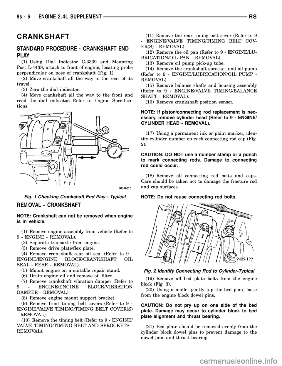
(1) Using Dial Indicator C-3339 and Mounting
Post L-4438, attach to front of engine, locating probe
perpendicular on nose of crankshaft (Fig. 1).
(2) Move crankshaft all the way to the rear of its
travel.
(3) Zero the dial indicator.
(4) Move crankshaft all the way to the front and
read the dial indicator. Refer to Engine Specifica-
tions.
REMOVAL - CRANKSHAFT
NOTE: Crankshaft can not be removed when engine
is in vehicle.
(1) Remove engine assembly from vehicle (Refer to
9 - ENGINE - REMOVAL).
(2) Separate transaxle from engine.
(3) Remove drive plate/flex plate.
(4) Remove crankshaft rear oil seal (Refer to 9 -
ENGINE/ENGINE BLOCK/CRANKSHAFT OIL
SEAL - REAR - REMOVAL).
(5) Mount engine on a suitable repair stand.
(6) Drain engine oil and remove oil filter.
(7) Remove crankshaft vibration damper (Refer to
9 - ENGINE/ENGINE BLOCK/VIBRATION
DAMPER - REMOVAL).
(8) Remove engine mount support bracket.
(9) Remove front timing belt covers (Refer to 9 -
ENGINE/VALVE TIMING/TIMING BELT COVER(S)
- REMOVAL).
(10) Remove the timing belt (Refer to 9 - ENGINE/
VALVE TIMING/TIMING BELT AND SPROCKETS -
REMOVAL).(11) Remove the rear timing belt cover (Refer to 9
- ENGINE/VALVE TIMING/TIMING BELT COV-
ER(S) - REMOVAL).
(12) Remove the oil pan (Refer to 9 - ENGINE/LU-
BRICATION/OIL PAN - REMOVAL).
(13) Remove oil pump pick-up tube.
(14) Remove the crankshaft sprocket and oil pump
(Refer to 9 - ENGINE/LUBRICATION/OIL PUMP -
REMOVAL).
(15) Remove balance shafts and housing assembly
(Refer to 9 - ENGINE/VALVE TIMING/BALANCE
SHAFT - REMOVAL).
(16) Remove crankshaft position sensor.
NOTE: If piston/connecting rod replacement is nec-
essary, remove cylinder head (Refer to 9 - ENGINE/
CYLINDER HEAD - REMOVAL).
(17) Using a permanent ink or paint marker, iden-
tify cylinder number on each connecting rod cap (Fig.
2).
CAUTION: DO NOT use a number stamp or a punch
to mark connecting rods. Damage to connecting
rod could occur.
(18) Remove all connecting rod bolts and caps.
Care should be taken not to damage the fracture rod
and cap surfaces.
NOTE: Do not reuse connecting rod bolts.
(19) Remove all bed plate bolts from the engine
block (Fig. 3).
(20) Using a mallet gently tap the bed plate loose
from the engine block dowel pins.
CAUTION: Do not pry up on one side of the bed
plate. Damage may occur to cylinder block to bed
plate alignment and thrust bearing.
(21) Bed plate should be removed evenly from the
cylinder block dowel pins to prevent damage to the
dowel pins and thrust bearing.
Fig. 1 Checking Crankshaft End Play - Typical
Fig. 2 Identify Connecting Rod to Cylinder-Typical
9s - 6 ENGINE 2.4L SUPPLEMENTRS
Page 1464 of 2585
(9) Install the main bearing/bed plate into engine
block.
(10) Before installing the bolts the threads should
be oiled with clean engine oil, wipe off any excess oil.
(11) Install main bearing bed plate to engine
block bolts 11, 17, and 20 finger tight. Tighten these
bolts down together until the bed plate contacts the
cylinder block.
(12) To ensure correct thrust bearing alignment,
perform the following steps:
²Step 1: Rotate crankshaft until number 4 piston
is at TDC.
²Step 2: Move crankshaft rearward to limits of
travel.
²Step 3: Then, move crankshaft forward to limits
of travel.
²Step 4: Wedge an appropriate tool between the
rear of the cylinder block(NOT BED PLATE)and
the rear crankshaft counterweight. This will hold the
crankshaft in it's furthest forward position.
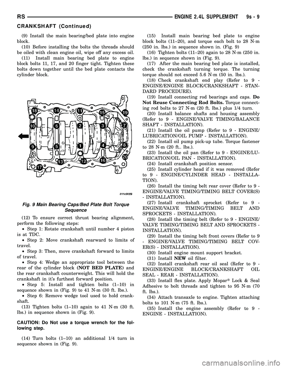
²Step 5: Install and tighten bolts (1±10) in
sequence shown in (Fig. 9) to 41 N´m (30 ft. lbs.).
²Step 6: Remove wedge tool used to hold crank-
shaft.
(13) Tighten bolts (1±10) again to 41 N´m (30 ft.
lbs.) in sequence shown in (Fig. 9).
CAUTION: Do Not use a torque wrench for the fol-
lowing step.
(14) Turn bolts (1±10) an additional 1/4 turn in
sequence shown in (Fig. 9).(15) Install main bearing bed plate to engine
block bolts (11±20), and torque each bolt to 28 N´m
(250 in. lbs.) in sequence shown in. (Fig. 9)
(16) Tighten bolts (11±20) again to 28 N´m (250 in.
lbs.) in sequence shown in (Fig. 9).
(17) After the main bearing bed plate is installed,
check the crankshaft turning torque. The turning
torque should not exceed 5.6 N´m (50 in. lbs.).
(18) Check crankshaft end play (Refer to 9 -
ENGINE/ENGINE BLOCK/CRANKSHAFT - STAN-
DARD PROCEDURE).
(19) Install connecting rod bearings and caps.Do
Not Reuse Connecting Rod Bolts.Torque connect-
ing rod bolts to 27 N´m (20 ft. lbs.) plus 1/4 turn.
(20) Install balance shafts and housing assembly
(Refer to 9 - ENGINE/VALVE TIMING/BALANCE
SHAFT - INSTALLATION).
(21) Install the oil pump (Refer to 9 - ENGINE/
LUBRICATION/OIL PUMP - INSTALLATION).
(22) Install oil pump pick-up tube. Torque fastener
to 28 N´m (20 ft.. lbs.).
(23) Install the oil pan (Refer to 9 - ENGINE/LU-
BRICATION/OIL PAN - INSTALLATION).
(24) Install crankshaft position sensor.
(25) Install cylinder head if it was removed (Refer
to 9 - ENGINE/CYLINDER HEAD - INSTALLA-
TION).
(26) Install the timing belt rear cover (Refer to 9 -
ENGINE/VALVE TIMING/TIMING BELT COVER(S)
- INSTALLATION).
(27) Install crankshaft sprocket (Refer to 9 -
ENGINE/VALVE TIMING/TIMING BELT AND
SPROCKETS - INSTALLATION).
(28) Install the timing belt (Refer to 9 - ENGINE/
VALVE TIMING/TIMING BELT AND SPROCKETS -
INSTALLATION).
(29) Install the timing belt front covers (Refer to 9
- ENGINE/VALVE TIMING/TIMING BELT COV-
ER(S) - INSTALLATION).
(30) Install engine mount support bracket.
(31) InstallNEWoil filter.
(32) Install crankshaft rear oil seal (Refer to 9 -
ENGINE/ENGINE BLOCK/CRANKSHAFT OIL
SEAL - REAR - INSTALLATION).
(33) Install flex plate. Apply MopartLock & Seal
Adhesive to bolt threads and tighten to 95 N´m (70
ft. lbs.).
(34) Attach transaxle to engine. Tighten attaching
bolts to 101 N´m (75 ft. lbs.).
(35) Install the engine assembly (Refer to 9 -
ENGINE - INSTALLATION).
Fig. 9 Main Bearing Caps/Bed Plate Bolt Torque
Sequence
RSENGINE 2.4L SUPPLEMENT9s-9
CRANKSHAFT (Continued)
Page 1487 of 2585
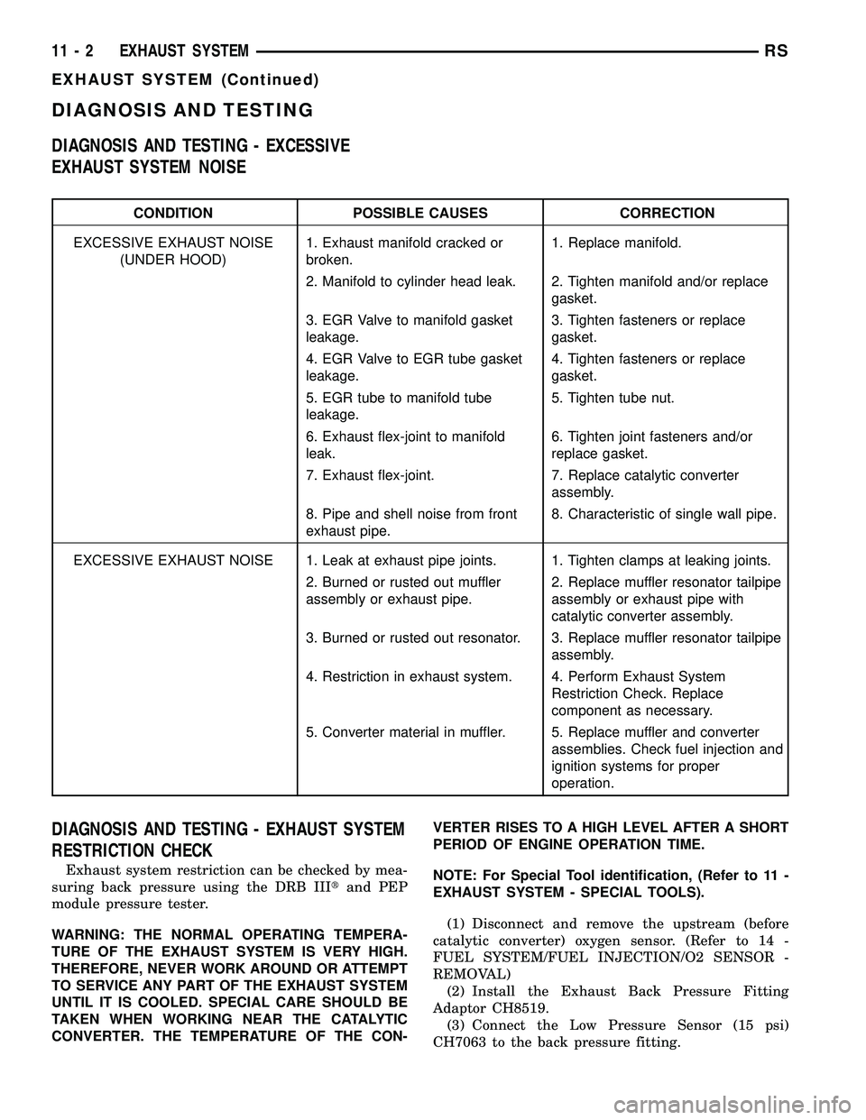
DIAGNOSIS AND TESTING
DIAGNOSIS AND TESTING - EXCESSIVE
EXHAUST SYSTEM NOISE
CONDITION POSSIBLE CAUSES CORRECTION
EXCESSIVE EXHAUST NOISE
(UNDER HOOD)1. Exhaust manifold cracked or
broken.1. Replace manifold.
2. Manifold to cylinder head leak. 2. Tighten manifold and/or replace
gasket.
3. EGR Valve to manifold gasket
leakage.3. Tighten fasteners or replace
gasket.
4. EGR Valve to EGR tube gasket
leakage.4. Tighten fasteners or replace
gasket.
5. EGR tube to manifold tube
leakage.5. Tighten tube nut.
6. Exhaust flex-joint to manifold
leak.6. Tighten joint fasteners and/or
replace gasket.
7. Exhaust flex-joint. 7. Replace catalytic converter
assembly.
8. Pipe and shell noise from front
exhaust pipe.8. Characteristic of single wall pipe.
EXCESSIVE EXHAUST NOISE 1. Leak at exhaust pipe joints. 1. Tighten clamps at leaking joints.
2. Burned or rusted out muffler
assembly or exhaust pipe.2. Replace muffler resonator tailpipe
assembly or exhaust pipe with
catalytic converter assembly.
3. Burned or rusted out resonator. 3. Replace muffler resonator tailpipe
assembly.
4. Restriction in exhaust system. 4. Perform Exhaust System
Restriction Check. Replace
component as necessary.
5. Converter material in muffler. 5. Replace muffler and converter
assemblies. Check fuel injection and
ignition systems for proper
operation.
DIAGNOSIS AND TESTING - EXHAUST SYSTEM
RESTRICTION CHECK
Exhaust system restriction can be checked by mea-
suring back pressure using the DRB IIItand PEP
module pressure tester.
WARNING: THE NORMAL OPERATING TEMPERA-
TURE OF THE EXHAUST SYSTEM IS VERY HIGH.
THEREFORE, NEVER WORK AROUND OR ATTEMPT
TO SERVICE ANY PART OF THE EXHAUST SYSTEM
UNTIL IT IS COOLED. SPECIAL CARE SHOULD BE
TAKEN WHEN WORKING NEAR THE CATALYTIC
CONVERTER. THE TEMPERATURE OF THE CON-VERTER RISES TO A HIGH LEVEL AFTER A SHORT
PERIOD OF ENGINE OPERATION TIME.
NOTE: For Special Tool identification, (Refer to 11 -
EXHAUST SYSTEM - SPECIAL TOOLS).
(1) Disconnect and remove the upstream (before
catalytic converter) oxygen sensor. (Refer to 14 -
FUEL SYSTEM/FUEL INJECTION/O2 SENSOR -
REMOVAL)
(2) Install the Exhaust Back Pressure Fitting
Adaptor CH8519.
(3) Connect the Low Pressure Sensor (15 psi)
CH7063 to the back pressure fitting.
11 - 2 EXHAUST SYSTEMRS
EXHAUST SYSTEM (Continued)