2004 CHRYSLER VOYAGER air conditioning
[x] Cancel search: air conditioningPage 186 of 2585

CAUTION: When tightening the primary and sec-
ondary brake tube nuts at master cylinder, be sure
brake tubes do not contact any other components
within the vehicle and that there is slack in the flex-
ible sections of the tubes. This is required due to
the movement between the ABS ICU and the master
cylinder while the vehicle is in motion.
(4) Connect primary and secondary brake tubes to
master cylinder primary and secondary ports (Fig.
49). Brake tubes must be held securely when tight-
ened to control orientation of flex section. Tighten
tube nuts to a torque of 17 N´m (145 in. lbs.).
(5) Install wiring harness connector to brake fluid
level switch mounted in brake fluid reservoir (Fig.
49).
(6) Install battery, clamp and nut.
(7) Install battery shield.
(8) Connect positive battery terminal.
(9) Connect negative battery terminal.
(10) Fill master cylinder with clean, fresh Mopart
Brake Fluid or equivalent.
(11) Road test vehicle to ensure proper operation of
brakes.
INSTALLATION - RHD
CAUTION: Different types of master cylinders are
used on this vehicle depending on brake options. If
a new master cylinder is being installed, be sure it
is the correct master cylinder for the type of brake
system the vehicle is equipped with.
CAUTION: When replacing the master cylinder on a
vehicle, a NEW vacuum seal MUST be installed on
the master cylinder.
(1) Install a NEW vacuum seal on master cylinder
making sure seal fits squarely in groove of master
cylinder casting.
(2) Position master cylinder on studs of power
brake booster, aligning booster push rod with master
cylinder piston.
(3) Install the two master cylinder mounting nuts
(Fig. 51). Tighten both mounting nuts to a torque of
25 N´m (225 in. lbs.).
CAUTION: When tightening the primary and sec-
ondary brake tube nuts at master cylinder, be sure
brake tubes do not contact any other components
within the vehicle and that there is slack in the flex-
ible sections of the tubes. This is required due to
the movement between the ABS ICU and the master
cylinder while the vehicle is in motion.(4) Connect primary and secondary brake tubes to
master cylinder primary and secondary ports (Fig.
51). Brake tubes must be held securely when tight-
ened to control orientation of flex section. Tighten
tube nuts to a torque of 17 N´m (145 in. lbs.).
(5) Install wiring harness connector to brake fluid
level switch mounted in brake fluid reservoir (Fig.
47).
(6) Install battery, clamp and nut.
(7) Install battery shield.
(8) Connect positive battery terminal.
(9) Connect negative battery terminal.
(10) Fill master cylinder with clean, fresh Mopart
Brake Fluid or equivalent.
(11) Road test vehicle to ensure proper operation of
brakes.
PEDAL TORQUE SHAFT - RHD
REMOVAL
(1) Remove the instrument panel. (Refer to 23 -
BODY/INSTRUMENT PANEL/INSTRUMENT
PANEL ASSEMBLY - REMOVAL)
(2) Remove the HVAC housing. (Refer to 24 -
HEATING & AIR CONDITIONING/DISTRIBUTION/
HVAC HOUSING - REMOVAL)
(3) Remove the retaining clip at the torque shaft
end of the brake pedal-to-torque shaft link. Remove
the link from the torque shaft. Discard the retaining
clip. It is not to be reused. Replace with a new clip
when reassembled.
(4) Locate the booster input rod-to-brake pedal
torque shaft connection and remove the retaining clip
(Fig. 54). Discard the retaining clip. It is not to be
reused. Replace with a new clip when reassembled.
(5) Remove the four (4) brake booster retaining
nuts from inside the passenger compartment (Fig.
55).
(6) Remove the retaining nut from the brake
booster bracket located above the booster in the
engine compartment (Fig. 55).
(7) Remove the power brake booster bracket.
(8) Rotate the pedal torque shaft and remove it out
the left side of the vehicle.
INSTALLATION
(1) Lubricate both ends of the torque shaft with
MS-4517 Lubricant or equivalent and install the
torque shaft from the left side reversing the removal
procedure.
(2) Install the brake booster bracket on the left
end of the shaft.
(3) Install the retaining nut for the brake booster
bracket in the engine compartment. Tighten the
mounting nut to a torque of 29 N´m (250 in. lbs.).
RSBRAKES - BASE5-39
MASTER CYLINDER (Continued)
Page 187 of 2585
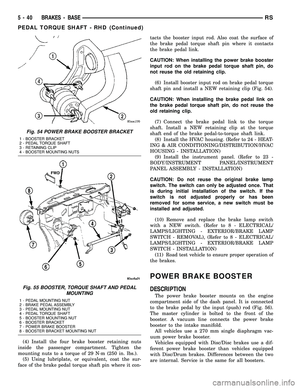
(4) Install the four brake booster retaining nuts
inside the passenger compartment. Tighten the
mounting nuts to a torque of 29 N´m (250 in. lbs.).
(5) Using lubriplate, or equivalent, coat the sur-
face of the brake pedal torque shaft pin where it con-tacts the booster input rod. Also coat the surface of
the brake pedal torque shaft pin where it contacts
the brake pedal link.
CAUTION: When installing the power brake booster
input rod on the brake pedal torque shaft pin, do
not reuse the old retaining clip.
(6) Install booster input rod on brake pedal torque
shaft pin and install a NEW retaining clip (Fig. 54).
CAUTION: When installing the brake pedal link on
the brake pedal torque shaft pin, do not reuse the
old retaining clip.
(7) Connect the brake pedal link to the torque
shaft. Install a NEW retaining clip at the torque
shaft end of the brake pedal-to-torque shaft link.
(8) Install the HVAC housing. (Refer to 24 - HEAT-
ING & AIR CONDITIONING/DISTRIBUTION/HVAC
HOUSING - INSTALLATION)
(9) Install the instrument panel. (Refer to 23 -
BODY/INSTRUMENT PANEL/INSTRUMENT
PANEL ASSEMBLY - INSTALLATION)
CAUTION: Do not reuse the original brake lamp
switch. The switch can only be adjusted once. That
is during initial installation of the switch. If the
switch is not adjusted properly or has been
removed for some service, a new switch must be
installed and adjusted.
(10) Remove and replace the brake lamp switch
with a NEW switch. (Refer to 8 - ELECTRICAL/
LAMPS/LIGHTING - EXTERIOR/BRAKE LAMP
SWITCH - REMOVAL), (Refer to 8 - ELECTRICAL/
LAMPS/LIGHTING - EXTERIOR/BRAKE LAMP
SWITCH - INSTALLATION)
(11) Road test vehicle to ensure proper operation of
the brakes.
POWER BRAKE BOOSTER
DESCRIPTION
The power brake booster mounts on the engine
compartment side of the dash panel. It is connected
to the brake pedal by the input (push) rod (Fig. 56).
The master cylinder is bolted to the front of the
booster. A vacuum line connects the power brake
booster to the intake manifold.
All vehicles use a 270 mm single diaphragm vac-
uum power brake booster.
Vehicles equipped with Disc/Disc brakes use a dif-
ferent power brake booster than vehicles equipped
with Disc/Drum brakes. Differences between the two
are internal. Service is the same for all boosters.
Fig. 54 POWER BRAKE BOOSTER BRACKET
1 - BOOSTER BRACKET
2 - PEDAL TORQUE SHAFT
3 - RETAINING CLIP
4 - BOOSTER MOUNTING NUTS
Fig. 55 BOOSTER, TORQUE SHAFT AND PEDAL
MOUNTING
1 - PEDAL MOUNTING NUT
2 - BRAKE PEDAL ASSEMBLY
3 - PEDAL MOUNTING NUT
4 - PEDAL TORQUE SHAFT
5 - BOOSTER MOUNTING NUT
6 - BOOSTER BRACKET
7 - POWER BRAKE BOOSTER
8 - BOOSTER BRACKET MOUNTING NUT
5 - 40 BRAKES - BASERS
PEDAL TORQUE SHAFT - RHD (Continued)
Page 285 of 2585

(24) Install knee blocker reinforcement plate (Fig.
53). (25) Connect parking brake release link to release
handle. (26) Install data link diagnostic connector to
mounting hole in reinforcement plate. (27) Install lower steering column cover/knee
blocker (Fig. 53). (28) Install throttle cable onto throttle body lever.
(Refer to 14 - FUEL SYSTEM/FUEL INJECTION/
THROTTLE CONTROL CABLE - INSTALLATION)
NOTE: When reconnecting the battery on a vehicle
that has had the airbag module removed, the fol-
lowing procedure should be used.
(29) Reconnect ground cable to negative post of
battery following special Diagnosis And Testing pro-
cedure. (Refer t o 8 - ELECTRICAL/RESTRAINTS -
DIAGNOSIS AND TESTING) (30) Test operation of adjustable pedals and all
functions that are steering column operated. If appli-
cable, reset radio and clock. (31) Road test the vehicle to ensure proper opera-
tion of steering and brake systems.
PEDAL TORQUE SHAFT - RHD
REMOVAL
(1) Remove the instrument panel. (Refer to 23 -
BODY/INSTRUMENT PANEL/INSTRUMENT
PANEL ASSEMBLY - REMOVAL) (2) Remove the HVAC housing. (Refer to 24 -
HEATING & AIR CONDITIONING/DISTRIBUTION/
HVAC HOUSING - REMOVAL) (3) Remove the retaining clip at the torque shaft
end of the brake pedal-to-torque shaft link. Remove
the link from the torque shaft. Discard the retaining
clip. It is not to be reused. Replace with a new clip
when reassembled. (4) Locate the booster input rod-to-brake pedal
torque shaft connection and remove the retaining clip
(Fig. 62). Discard the retaining clip. It is not to be
reused. Replace with a new clip when reassembled. (5) Remove the four (4) brake booster retaining
nuts from inside the passenger compartment (Fig.
63). (6) Remove the retaining nut from the brake
booster bracket located above the booster in the
engine compartment (Fig. 63). (7) Remove the power brake booster bracket.
(8) Rotate the pedal torque shaft and remove it out
the left side of the vehicle.
Fig. 62 POWER BRAKE BOOSTER BRACKET
1 - BOOSTER BRACKET
2 - PEDAL TORQUE SHAFT
3 - RETAINING CLIP
4 - BOOSTER MOUNTING NUTS
Fig. 63 BOOSTER, TORQUE SHAFT AND PEDAL MOUNTING
1 - PEDAL MOUNTING NUT
2 - BRAKE PEDAL ASSEMBLY
3 - PEDAL MOUNTING NUT
4 - PEDAL TORQUE SHAFT
5 - BOOSTER MOUNTING NUT
6 - BOOSTER BRACKET
7 - POWER BRAKE BOOSTER
8 - BOOSTER BRACKET MOUNTING NUT
5s - 42 BRAKESRS
PEDALS - ADJUSTABLE (Continued)
Page 286 of 2585

INSTALLATION
(1) Lubricate both ends of the torque shaft with
MS-4517 Lubricant or equivalent and install the
torque shaft from the left side reversing the removal
procedure. (2) Install the brake booster bracket on the left
end of the shaft. (3) Install the retaining nut for the brake booster
bracket in the engine compartment. Tighten the
mounting nut to a torque of 29 N´m (250 in. lbs.). (4) Install the four brake booster retaining nuts
inside the passenger compartment. Tighten the
mounting nuts to a torque of 29 N´m (250 in. lbs.). (5) Using lubriplate, or equivalent, coat the sur-
face of the brake pedal torque shaft pin where it con-
tacts the booster input rod. Also coat the surface of
the brake pedal torque shaft pin where it contacts
the brake pedal link.
CAUTION: When installing the power brake booster
input rod on the brake pedal torque shaft pin, do
not reuse the old retaining clip.
(6) Install booster input rod on brake pedal torque
shaft pin and install a NEW retaining clip (Fig. 62).
CAUTION: When installing the brake pedal link on
the brake pedal torque shaft pin, do not reuse the
old retaining clip.
(7) Connect the brake pedal link to the torque
shaft. Install a NEW retaining clip at the torque
shaft end of the brake pedal-to-torque shaft link. (8) Install the HVAC housing. (Refer to 24 - HEAT-
ING & AIR CONDITIONING/DISTRIBUTION/HVAC
HOUSING - INSTALLATION) (9) Install the instrument panel. (Refer to 23 -
BODY/INSTRUMENT PANEL/INSTRUMENT
PANEL ASSEMBLY - INSTALLATION)
CAUTION: Do not reuse the original brake lamp
switch. The switch can only be adjusted once. That
is during initial installation of the switch. If the
switch is not adjusted properly or has been
removed for some service, a new switch must be
installed and adjusted.
(10) Remove and replace the brake lamp switch
with a NEW switch. (Refer t o 8 - ELECTRICAL/
LAMPS/LIGHTING - EXTERIOR/BRAKE LAMP
SWITCH - REMOVAL), (Refer t o 8 - ELECTRICAL/
LAMPS/LIGHTING - EXTERIOR/BRAKE LAMP
SWITCH - INSTALLATION) (11) Road test vehicle to ensure proper operation of
the brakes.
POWER BRAKE BOOSTER
DESCRIPTION
The power brake booster mounts on the engine
compartment side of the dash panel. It is connected
to the brake pedal by the input (push) rod (Fig. 64).
The master cylinder is bolted to the front of the
booster. A vacuum line connects the power brake
booster to the intake manifold.
All Left-Hand-Drive (LHD) vehicles use a 270 mm
single diaphragm vacuum power brake booster. All
Right-Hand-Drive (RHD) vehicles use a 225/200 mm
tandem diaphragm vacuum power brake booster. Vehicles equipped with Disc/Disc brakes use a dif-
ferent power brake booster than vehicles equipped
with Disc/Drum brakes. Differences between the two
are internal. Service is the same for all boosters. The power brake booster can be identified by the
tag attached to the body of the booster (Fig. 65). This
tag contains the production part number, the date it
was built, and who the manufacturer of the power
brake booster is.
Fig. 64 Power Brake Booster (Typical)
1 - VACUUM CHECK VALVE
2 - POWER BRAKE BOOSTER ASSEMBLY
3 - INPUT ROD
4 - POWER BOOSTER ASSEMBLY TO DASH PANEL MOUNTING
STUDS (4)
5 - MASTER CYLINDER MOUNTING STUDS (2)
6 - OUTPUT ROD
RS BRAKES5s-43
PEDAL TORQUE SHAFT - RHD (Continued)
Page 329 of 2585

(2) Install clutch release bearing to lever. Apply
grease to interface points. Make sure release bearing
retainers engage lever pocket as shown in (Fig. 10).
(3) Apply grease to pivot ball, and on release lever
at slave cylinder contact point.
(4) Install clutch release bearing/lever assembly
into position by sliding bearing onto input bearing
retainer, and using moderate hand pressure to seat
release lever to pivot ball(s) (Fig. 11). A ªpopº sound
should be heard. Verify proper engagement by lightly
pulling outward on lever at pivot ball location, and
then actuating lever and bearing to ensure proper
operation.
MASTER CYLINDER - RHD
REMOVAL
(1) Disconnect battery negative cable.
(2) Remove master cylinder to clutch pedal pin
retainer clip. Disengage pushrod from clutch pedal
pin (Fig. 13).
(3) Disengage master cylinder grommet from cowl
panel.
(4) Remove battery and tray.
(5)Diesel models:Remove windshield wiper mod-
ule assembly. (Refer to 8 - ELECTRICAL/WIPERS/
WASHERS/WIPER MODULE - REMOVAL)
(6) Discharge Air Conditioning system. (Refer to 24
- HEATING & AIR CONDITIONING/PLUMBING/
REFRIGERANT - STANDARD PROCEDURE)(7) Remove suction/discharge line from evaporator
junction block.
(8) Using tool 6638A, disconnect clutch hydraulic
ªquick-connectº fitting (Fig. 12).
(9) Remove clutch master cylinder tubing from
retainers in engine compartment.
(10) Remove clutch master cylinder from dash
panel/clutch pedal bracket by rotating 45É clockwise
and pulling outward towards engine (Fig. 13).
(11) Carefully guide clutch master cylinder and
hydraulic plumbing from engine compartment.
Fig. 10 Release Bearing-to-Lever
1 - RETAINER (2)
2 - RELEASE LEVER
3 - RELEASE BEARING
Fig. 11 Release Bearing and Lever
1 - RELEASE LEVER
2 - RELEASE BEARING
Fig. 12 Disconnect Quick-Connect Using Tool 6638A
1 - QUICK CONNECT FITTING
2 - TOOL 6638A
6 - 8 CLUTCHRS
CLUTCH RELEASE LEVER AND BEARING (Continued)
Page 330 of 2585

INSTALLATION
(1) Carefully route master cylinder plumbing into
engine compartment as removed and position master
cylinder to dash panel hole.
(2) Rotate master cylinder 45É clockwise, insert
into dash panel hole, engaging clutch pedal bracket.
Rotate master cylinder 45É counter-clockwise, secur-
ing it to pedal bracket (Fig. 13).
(3) Install and secure grommet to dash panel.
(4) Connect pushrod to clutch pedal pin. Install
retainer clip (Fig. 13).
(5) Secure master cylinder plumbing to retainers
in engine compartment.
(6) Connect clutch master cylinder plumbing to
slave cylinder ªquick connectº fitting. An audible
ªclickº should be heard. Verify connection by pulling
outward.
(7) Connect A/C suction/discharge line to evapora-
tor junction block.
(8)Diesel models:Install wiper module assembly.
(Refer to 8 - ELECTRICAL/WIPERS/WASHERS/
WIPER MODULE - INSTALLATION)
(9) Install battery and tray.
(10) Connect battery negative cable
(11) Charge Air Conditioning system. (Refer to 24 -
HEATING & AIR CONDITIONING/PLUMBING/RE-
FRIGERANT - STANDARD PROCEDURE)
MASTER CYLINDER - LHD
REMOVAL
(1) Disconnect battery cables.
(2) Remove instrument panel lower silencer (Fig.
14).
(3) Remove knee bolster (Fig. 15).
(4) Remove clutch master cylinder pushrod
retainer clip (Fig. 16).
(5) Disconnect pushrod from clutch pedal (Fig. 16).
(6) Remove battery shield.
(7) Remove battery.
(8) Remove battery tray.
(9) Remove windshield wiper module assembly
(Refer to 8 - ELECTRICAL/WIPERS/WASHERS/
WIPER MODULE - REMOVAL).
Fig. 13 Clutch Master Cylinder at Pedal Bracket
1 - CLUTCH MASTER CYLINDER
2 - RETAINER CLIP
3 - CLUTCH PEDAL PIN
4 - PUSH RODFig. 14 Instrument Panel Lower Silencer
1 - INSTRUMENT PANEL LOWER SILENCER
Fig. 15 Knee Bolster
1 - KNEE BOLSTER
RSCLUTCH6-9
MASTER CYLINDER - RHD (Continued)
Page 342 of 2585

STANDARD PROCEDURE - COOLING SYSTEM
FILLING
Remove radiator pressure cap (Fig. 6) and fill sys-
tem, using a 50/50 mix of MopartAntifreeze/Coolant,
5 Year/100,000 Mile Formula and distilled water.
Continue filling system until full.Be careful not
to spill coolant on drive belts or the generator.
For cooling system capacity, (Refer to LUBRICATION
& MAINTENANCE/FLUID CAPACITIES - SPECIFI-
CATIONS).
Fill coolant recovery/reserve container (Fig. 6) to at
least the MAX mark with 50/50 solution. It may be
necessary to add coolant to the recovery/reserve con-
tainer after three or four warm up/cool down cycles
to maintain coolant level between the MAX and MIN
mark. This will allow trapped air to be removed from
the system.
STANDARD PROCEDURE - ADDING
ADDITIONAL COOLANT
The radiator cap should not be removed.
When additional coolant is needed to maintain this
level, it should be added to the coolant recovery/re-
serve container (Fig. 6). Use only 50/50 mix of ethyl-
ene glycol type antifreeze and distilled water. For the
recommeded antifreeze/coolant type (Refer to LUBRI-
CATION & MAINTENANCE/FLUID TYPES -
DESCRIPTION).
CAUTION: Do not use well water, or suspect water
supply in cooling system. A 50/50 ethylene glycol
and distilled water mix is recommended. For the
recommeded antifreeze/coolant type (Refer to
LUBRICATION & MAINTENANCE/FLUID TYPES -
DESCRIPTION).
STANDARD PROCEDURE - COOLANT LEVEL
CHECK
NOTE: Do not remove radiator cap for routine cool-
ant level inspections.
The coolant reserve system provides a quick visual
method for determining the coolant level without
removing the radiator cap.With the engine cold
and not running,simply observe the level of the
coolant in the recovery/reserve container (Fig. 6). The
coolant level should be between the MIN and MAX
marks.
SPECIFICATIONS
ACCESSORY DRIVE BELT TENSION
ACCESSORY DRIVE BELT TENSION
2.4L ENGINE
Air Conditioning
Compressor/GeneratorDynamic Tensioner
Power
SteeringNew Belt534 - 756 N
(120 - 170 lbs.)
Used Belt*356 - 534 N
(80 - 120 lbs)
*Belt is considered used after 15 minutes of run-in
time
3.3/3.8L ENGINES
Air Conditioning Compressor
Dynamic Tensioner
Generator/Water Pump/
Power Steering
TORQUE
DESCRIPTION N´mFt.
Lbs.In.
Lbs.
Accessory Drive Belt Tensioner
Assembly (3.3/3.8L)ÐBolt28 Ð 250
Engine Coolant Temperature
Sensor
(2.4 & 3.3/3.8L) 7 Ð 60
Generator & A/C Compressor
Drive Belt Tensioner Assembly
(2.4L)ÐBolt54 40 Ð
Coolant Outlet Connector/
Thermostat Housing
(2.4 & 3.3/3.8L)ÐBolts 28 Ð 250
Water Pump
(2.4 & 3.3/3.8L)ÐBolts 12 Ð 105
Water Pump Inlet Tube
(2.4L)ÐBolts12 Ð 105
Water Pump Inlet Tube
(3.3/3.8L)ÐBolts28 Ð 250
Water Pump Pulley (3.3/3.8L)Ð
Bolts28 Ð 250
Radiator to A/C CondenserÐ
Screws5Ð45
Radiator FanÐScrews 5 Ð 45
Radiator Mounting (Upper
Bracket)ÐNuts12 Ð 105
RSCOOLING7-5
COOLING (Continued)
Page 345 of 2585

CONDITION POSSIBLE CAUSES CORRECTIONS
BELT ROLLED OVER IN GROOVE
OR BELT JUMPS OFF1. Broken cord in belt 1. Replace belt
2. Belt too loose, or too tight 2. (a) Replace belt (auto-tensioned
belts.)
(b) Adjust power steering belt
tension (4 cyl. engine)
3. Misaligned pulleys 3. Align accessories
4. Non-uniform groove or eccentric
pulley4. Replace pulley
DRIVE BELTS - 2.4L
STANDARD PROCEDURE - CHECKING POWER
STEERING BELT TENSION
WARNING: DO NOT CHECK BELT TENSION WITH
ENGINE RUNNING.
Accessory drive belt tension can be measured with
Special Tool 8371 ± Belt Tension Gauge Adapter, and
the DRBIIItusing the following procedures:
(1) Connect 8371 to the DRBIIItfollowing the
instructions provided with tool.
(2) Place end of microphone probe approximately
2.54 cm (1 in.) from belt at belt center span location
shown in (Fig. 1).
(3) Pluck the belt a minimum of 3 times. (Use your
finger or other suitable tool) The frequency of the
belt in hertz (Hz) will display on DRBIIItscreen.
(4) Adjust belt to obtain proper frequency (ten-
sion). Refer to ACCESSORY DRIVE BELT TENSION
CHART for belt tension specifications.
ACCESSORY DRIVE BELT TENSION CHART -
2.4L
Accessory Drive Belt Belt Tension
Air Conditioning
Compressor/GeneratorDynamic Tensioner
Power Steering PumpNew178 - 212
Hz
Used* 145 - 178
Hz
*A belt is considered used after 15 minutes of run-in
time.
REMOVAL
GENERATOR AND AIR CONDITIONING BELT
(1) Raise vehicle on hoist.
(2) Remove the drive belt shield (Fig. 7).
WARNING: DO NOT ALLOW DRIVE BELT TEN-
SIONER TO SNAP BACK, AS DAMAGE TO TEN-
SIONER AND/OR PERSONAL INJURY COULD
RESULT.
Fig. 1 Power Steering Belt - Center Span Location
1 - POWER STEERING BELT CENTER SPAN LOCATION
7 - 8 ACCESSORY DRIVERS
DRIVE BELTS (Continued)