2004 CHRYSLER VOYAGER wheel torque
[x] Cancel search: wheel torquePage 2101 of 2585
INSTALLATION
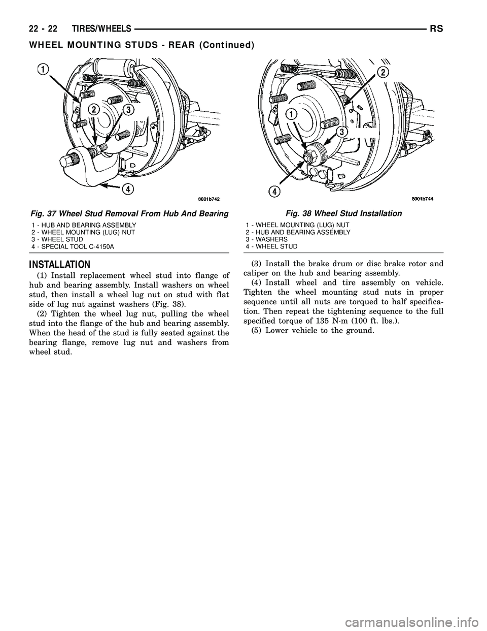
(1) Install replacement wheel stud into flange of
hub and bearing assembly. Install washers on wheel
stud, then install a wheel lug nut on stud with flat
side of lug nut against washers (Fig. 38).
(2) Tighten the wheel lug nut, pulling the wheel
stud into the flange of the hub and bearing assembly.
When the head of the stud is fully seated against the
bearing flange, remove lug nut and washers from
wheel stud.(3) Install the brake drum or disc brake rotor and
caliper on the hub and bearing assembly.
(4) Install wheel and tire assembly on vehicle.
Tighten the wheel mounting stud nuts in proper
sequence until all nuts are torqued to half specifica-
tion. Then repeat the tightening sequence to the full
specified torque of 135 N´m (100 ft. lbs.).
(5) Lower vehicle to the ground.
Fig. 37 Wheel Stud Removal From Hub And Bearing
1 - HUB AND BEARING ASSEMBLY
2 - WHEEL MOUNTING (LUG) NUT
3 - WHEEL STUD
4 - SPECIAL TOOL C-4150A
Fig. 38 Wheel Stud Installation
1 - WHEEL MOUNTING (LUG) NUT
2 - HUB AND BEARING ASSEMBLY
3 - WASHERS
4 - WHEEL STUD
22 - 22 TIRES/WHEELSRS
WHEEL MOUNTING STUDS - REAR (Continued)
Page 2102 of 2585
TIRES/WHEELS
TABLE OF CONTENTS
page page
TIRE PRESSURE MONITORING............... 1TIRES................................... 5
TIRE PRESSURE MONITORING
TABLE OF CONTENTS
page page
TIRE PRESSURE MONITORING DESCRIPTION ..........................1
OPERATION ............................1
SENSOR - TPM DESCRIPTION ..........................1
OPERATION ............................2
CAUTION ..............................2 DIAGNOSIS AND TESTING - TIRE PRESSURE
SENSOR .............................2
STANDARD PROCEDURE - TIRE PRESSURE SENSOR RETRAIN .....................2
REMOVAL .............................2
INSTALLATION ..........................3
TIRE PRESSURE MONITORING
DESCRIPTION
Some versions of this vehicle are equipped with a
Tire Pressure Monitoring (TPM) system. It monitors
air pressure in the four road tires. Pressure in the
spare tire is not monitored. There is a sensor (transmitter) in each of the vehi-
cle's four road wheels that is built in to the valve
stem. The system alerts the driver when tire pres-
sure falls outside predetermined thresholds (pressure
too low or too high). A message is then displayed on
the Compass Mini Trip Computer (CMTC). For further information, refer to the Owners Man-
ual or the appropriate diagnostic information.
OPERATION
The Tire Pressure Monitoring (TPM) system uses
radio and sensor technology to monitor tire air pres-
sure levels. Sensors, mounted to each road wheel as
part of the valve stem, transmit an RF frequency
indicating their individual pressure to a receiver
located in the Sentry Key Remote Entry Module
(SKREEM). These transmissions occur approximately
once every minute at speeds over 13 mph (20 km/h).
The Tire Pressure Monitoring system remains active
even if no tire pressure related message is displayed.
SENSOR - TPM
DESCRIPTION
On vehicles equipped with Tire Pressure Monitor-
ing, one tire pressure sensor is mounted to each
wheel (Fig. 2). Each sensor has an internal battery
that lasts up to 10 years. The battery is not service-
able. At the time of battery failure, the sensor must
be replaced. The serviceable components of the tire
pressure sensor are: ² Sensor-To-Wheel Grommet
² Valve Stem Cap
² Valve Stem Core
Valve stem caps and cores are specifically designed
for the tire pressure monitoring sensors. Although
similar to standard valve stem caps and cores, they
are different.
CAUTION: Do not use a standard valve stem cap or
core in a tire pressure sensor. Always use the orig-
inal equipment style sensor cap and core.
CAUTION: Do not reuse the Sensor-To Wheel Grom-
met. Always use a new grommet when installing a
pressure sensor and properly torque the sensor
nut.
RS TIRES/WHEELS22s-1
Page 2104 of 2585

INSTALLATION
NOTE: Before reinstalling a tire pressure sensor,
replace sealing grommet at base of valve stem.(1) Wipe area clean where sensor sealing grommet
contacts wheel. Make sure surface of wheel is not
damaged. (2) Install sensor in wheel as shown (Fig. 2). Do
not attempt to mount sensor otherwise, damage may
occur. (3) Using a thin wall socket, install special sensor
nut (Fig. 2). Tighten nut to 4 N´m (35 in. lbs.) torque.
CAUTION: Over-torquing the sensor nut by as little
as 12 N´m (106 in. lbs.) may result in sensor sepa-
ration from the valve stem. Under this condition,
the sensor may still function, however, the condi-
tion should be corrected immediately.
(4) Mount tire on wheel following tire changer
manufacturers instructions, paying special attention
to the following to avoid damaging tire pressure sen-
sor: (a) Rotating Wheel Tire Changers - Once the
wheel is mounted to the changer, position the sen-
sor valve stem approximately 210É from the head
of the changer in a clockwise direction before rotat-
ing the wheel (also in a clockwise direction) to
mount the tire (Fig. 3). Use this procedure on both
the upper and lower tire beads. (b) Rotating Tool Tire Changers - Position the
wheel on the changer so that the sensor valve stem
is approximately 210É from the head of the changer
in a clockwise direction from the mounting end of
the tool (Fig. 4) Make sure the sensor is clear of
the lower bead breaker area to avoid damaging the
sensor when the breaker rises (Fig. 4). Rotate the
tool in a counterclockwise direction to mount the
tire. Use this procedure on both the upper and
lower tire beads.
Fig. 1 Start Mount/Dismount Tool Within 10 Degrees Of Valve Stem
Fig. 2 Sensor Mounting To Wheel
1 - TIRE PRESSURE SENSOR
2 - WHEEL
3 - NUT
Fig. 3 Mounting Tire Using Rotating Wheel Machine
1 - HEAD OF CHANGER LOCATED HERE
2 - VALVE STEM
RS TIRE PRESSURE MONITORING22s-3
SENSOR - TPM (Continued)
Page 2110 of 2585
pressures may increase from 2 to 6 pounds per
square inch (psi) (14 to 41 kPa) during operation. Do
not reduce this normal pressure buildup.Improper inflation can cause:
² Uneven wear patterns
² Reduced tread life
² Reduced fuel economy
² Unsatisfactory ride
² The vehicle to drift.
WARNING: OVER OR UNDER INFLATED TIRES CAN
AFFECT VEHICLE HANDLING. THE TIRE CAN FAIL
SUDDENLY, RESULTING IN LOSS OF VEHICLE
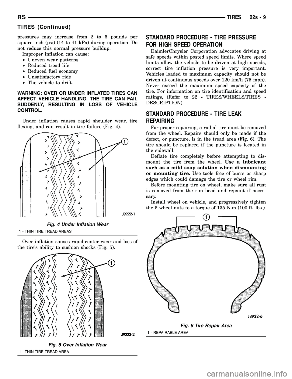
CONTROL. Under inflation causes rapid shoulder wear, tire
flexing, and can result in tire failure (Fig. 4).
Over inflation causes rapid center wear and loss of
the tire's ability to cushion shocks (Fig. 5).STANDARD PROCEDURE - TIRE PRESSURE
FOR HIGH SPEED OPERATION
DaimlerChrysler Corporation advocates driving at
safe speeds within posted speed limits. Where speed
limits allow the vehicle to be driven at high speeds,
correct tire inflation pressure is very important.
Vehicles loaded to maximum capacity should not be
driven at continuous speeds over 120 km/h (75 mph).
Never exceed the maximum speed capacity of the
tire. For information on tire identification and speed
ratings, (Refer to 22 - TIRES/WHEELS/TIRES -
DESCRIPTION).
STANDARD PROCEDURE - TIRE LEAK
REPAIRING
For proper repairing, a radial tire must be removed
from the wheel. Repairs should only be made if the
defect, or puncture, is in the tread area (Fig. 6). The
tire should be replaced if the puncture is located in
the sidewall. Deflate tire completely before attempting to dis-
mount the tire from the wheel. Use a lubricant
such as a mild soap solution when dismounting
or mounting tire. Use tools free of burrs or sharp
edges which could damage the tire or wheel rim. Before mounting tire on wheel, make sure all rust
is removed from the rim bead and repaint if neces-
sary. Install wheel on vehicle, and progressively tighten
the 5 wheel nuts to a torque of 135 N´m (100 ft. lbs.).
Fig. 4 Under Inflation Wear
1 - THIN TIRE TREAD AREAS
Fig. 5 Over Inflation Wear
1 - THIN TIRE TREAD AREA
Fig. 6 Tire Repair Area
1 - REPAIRABLE AREA
RS TIRES22s-9
TIRES (Continued)
Page 2126 of 2585
CHECK STRAP
REMOVAL
(1) Remove front door trim panel.
(2) Remove front door watershield (Refer to 23 -
BODY/DOOR - FRONT/WATERSHIELD -
REMOVAL).
(3) Remove front door speaker, if equipped.
(4) Remove bolts attaching door check strap to
A-pillar.
(5) Remove nuts attaching check strap to door end
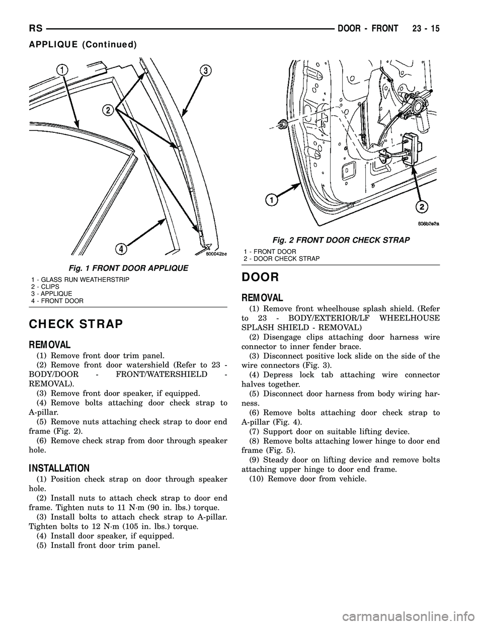
frame (Fig. 2).
(6) Remove check strap from door through speaker
hole.
INSTALLATION
(1) Position check strap on door through speaker
hole.
(2) Install nuts to attach check strap to door end
frame. Tighten nuts to 11 N´m (90 in. lbs.) torque.
(3) Install bolts to attach check strap to A-pillar.
Tighten bolts to 12 N´m (105 in. lbs.) torque.
(4) Install door speaker, if equipped.
(5) Install front door trim panel.
DOOR
REMOVAL
(1) Remove front wheelhouse splash shield. (Refer
to 23 - BODY/EXTERIOR/LF WHEELHOUSE
SPLASH SHIELD - REMOVAL)
(2) Disengage clips attaching door harness wire
connector to inner fender brace.
(3) Disconnect positive lock slide on the side of the
wire connectors (Fig. 3).
(4) Depress lock tab attaching wire connector
halves together.
(5) Disconnect door harness from body wiring har-
ness.
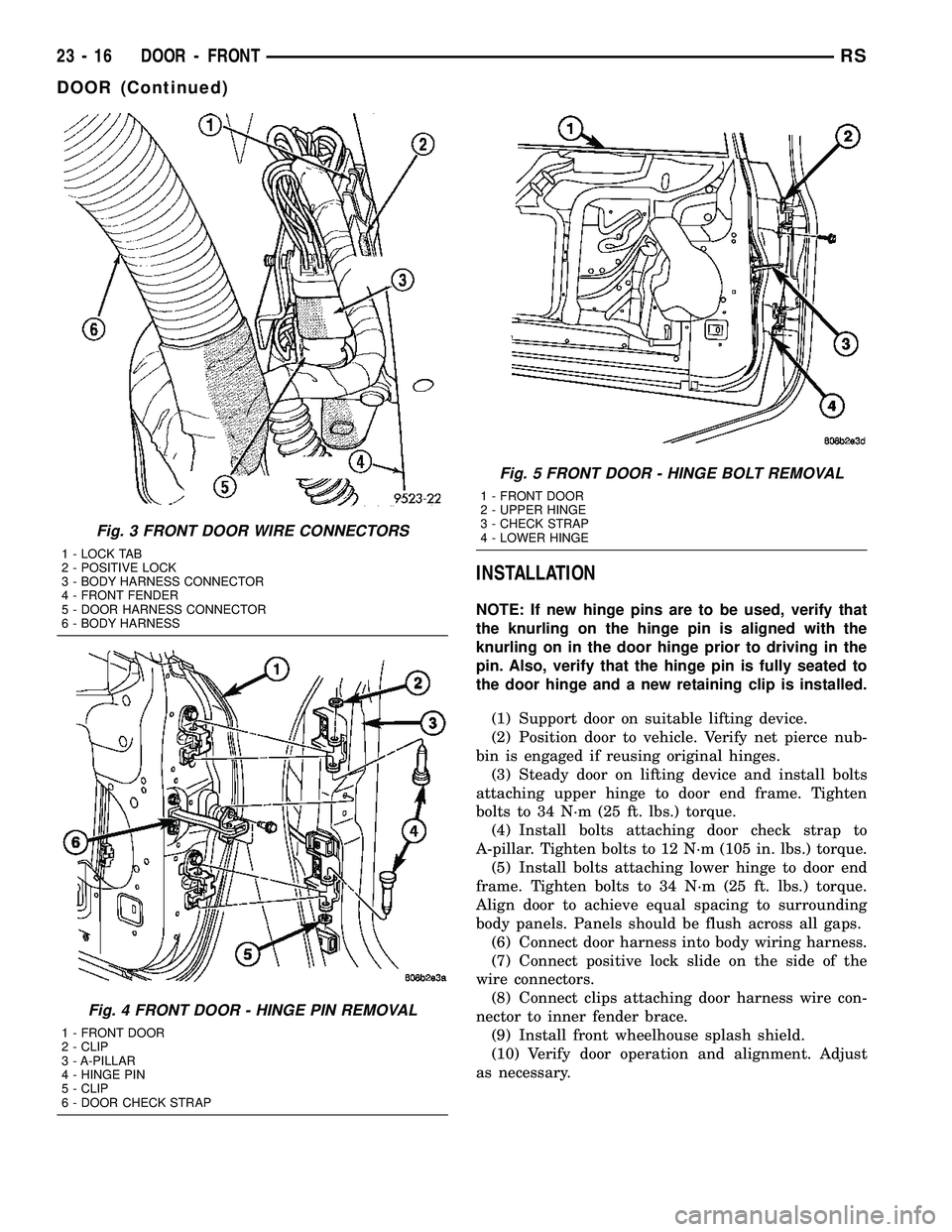
(6) Remove bolts attaching door check strap to
A-pillar (Fig. 4).
(7) Support door on suitable lifting device.
(8) Remove bolts attaching lower hinge to door end
frame (Fig. 5).
(9) Steady door on lifting device and remove bolts
attaching upper hinge to door end frame.
(10) Remove door from vehicle.
Fig. 1 FRONT DOOR APPLIQUE
1 - GLASS RUN WEATHERSTRIP
2 - CLIPS
3 - APPLIQUE
4 - FRONT DOOR
Fig. 2 FRONT DOOR CHECK STRAP
1 - FRONT DOOR
2 - DOOR CHECK STRAP
RSDOOR - FRONT23-15
APPLIQUE (Continued)
Page 2127 of 2585
INSTALLATION
NOTE: If new hinge pins are to be used, verify that
the knurling on the hinge pin is aligned with the
knurling on in the door hinge prior to driving in the
pin. Also, verify that the hinge pin is fully seated to
the door hinge and a new retaining clip is installed.
(1) Support door on suitable lifting device.
(2) Position door to vehicle. Verify net pierce nub-
bin is engaged if reusing original hinges.
(3) Steady door on lifting device and install bolts
attaching upper hinge to door end frame. Tighten
bolts to 34 N´m (25 ft. lbs.) torque.
(4) Install bolts attaching door check strap to
A-pillar. Tighten bolts to 12 N´m (105 in. lbs.) torque.
(5) Install bolts attaching lower hinge to door end
frame. Tighten bolts to 34 N´m (25 ft. lbs.) torque.
Align door to achieve equal spacing to surrounding
body panels. Panels should be flush across all gaps.
(6) Connect door harness into body wiring harness.
(7) Connect positive lock slide on the side of the
wire connectors.
(8) Connect clips attaching door harness wire con-
nector to inner fender brace.
(9) Install front wheelhouse splash shield.
(10) Verify door operation and alignment. Adjust
as necessary.
Fig. 3 FRONT DOOR WIRE CONNECTORS
1 - LOCK TAB
2 - POSITIVE LOCK
3 - BODY HARNESS CONNECTOR
4 - FRONT FENDER
5 - DOOR HARNESS CONNECTOR
6 - BODY HARNESS
Fig. 4 FRONT DOOR - HINGE PIN REMOVAL
1 - FRONT DOOR
2 - CLIP
3 - A-PILLAR
4 - HINGE PIN
5 - CLIP
6 - DOOR CHECK STRAP
Fig. 5 FRONT DOOR - HINGE BOLT REMOVAL
1 - FRONT DOOR
2 - UPPER HINGE
3 - CHECK STRAP
4 - LOWER HINGE
23 - 16 DOOR - FRONTRS
DOOR (Continued)
Page 2166 of 2585

(3) Align with paint breaks around bolt heads.
(4) Install bolts attaching ends of crossmember to
radiator closure panel (Fig. 14). Tighten bolts to 19
N´m (14 ft. lbs.) torque.
(5) Install bolts attaching radiator isolators to
crossmember.
(6) Install screw attaching coolant recovery bottle
to crossmember.
(7) Install bolt attaching air cleaner housing to
crossmember.
(8) Install engine air inlet resonator.
(9) Install radiator sight shield.
(10) Install hood prop rod.
(11) Align hood latch by placing latch over net
pierce tabs. If alignment is required, flatten tabs.
(12) Install bolts attaching hood latch to cross-
member. Tighten bolts to 13.5 N´m (10 ft. lbs.)
torque.
(13) Verify hood latch operation and hood align-
ment.
FRONT WHEELHOUSE
SPLASH SHIELD
REMOVAL
(1) Hoist and support vehicle on safety stands.
(Refer to LUBRICATION & MAINTENANCE/HOIST-
ING - STANDARD PROCEDURE).
(2) Remove front wheel.
(3) Remove push pin fasteners attaching splash
shield to frame rail forward of suspension.
(4) Remove push pin fasteners attaching splash
shield to frame rail rearward of suspension.
(5) Remove screws attaching wheelhouse splash
shield to front fender and front bumper fascia.
(6) Remove splash shield from vehicle (Fig. 15).
INSTALLATION
(1) Place splash shield in position on vehicle (Fig.
15).
(2) Install push pin fasteners attaching splash
shield to frame rail forward of suspension.
(3) Install push pin fasteners attaching splash
shield to frame rail rearward of suspension.
(4) Install screws attaching wheelhouse splash
shield to front fender.
(5) Install front wheel.
(6) Lower vehicle.
LUGGAGE RACK RISER
REMOVAL
(1) Remove two fasteners from the front riser.
Gently pull up on the luggage rack side rail and
detach the riser snap to remove riser from the rail
(Fig. 16).
(2) Repeat for the opposite side, if necessary.
(3) Remove front riser(s) from vehicle (Fig. 17).
Fig. 15 FRONT WHEELHOUSE SPLASH SHIELD
1 - FRONT FENDER WHEELHOUSE SPLASH SHIELD
2 - PUSH PIN FASTENERS
3 - ACCESSORY DRIVE SPLASH SHIELD
4 - SCREWS
Fig. 16 LUGGAGE RACK RISER COVER
1 - FRONT RISER COVER
2 - LOCK TABS
3 - LUGGAGE RACK SIDE RAIL
4 - FRONT RISER
RSEXTERIOR23-55
GRILLE OPENING REINFORCEMENT (Continued)
Page 2168 of 2585
INSTALLATION
NOTE: The crossbar assemblies are designed to be
installed in only one way. Check top and bottom
surfaces of the crossbar for the word FRONT and
directional arrows. The directional arrows must
point toward the front of the vehicle.
(1) Place crossbar in position on vehicle.
(2) Work from side to side sliding the crossbar
assembly back a little at a time to ensure it remains
perpendicular to the side rails.
(3) Position first crossbar assembly crossbar at the
second most rearward locator holes. Press the top of
the stanchion lever to lock it into position.
(4) Position the second crossbar assembly in the
second hole from the front. Lock into place.
(5) Place luggage rack riser into position.
(6) Install two fasteners into riser. Tighten fasten-
ers to 4 mm (35 in. lbs.) torque.
REAR QUARTER PANEL/
FENDER AIR EXHAUSTER
DESCRIPTION
Air exhausters, designed to conform to the body
structure, allow air entering at the front of the vehi-
cle to flow out the back. By reducing air pressure
within the vehicle, the exhausters also reduce blower
noise at any given air flow level compared to operat-
ing without them and help reduce door closing effort.
They are located in the lower rear comers of the
body.
REMOVAL
SHORT WHEELBASE
(1) Remove the rear fascia from the body. (Refer to
13 - FRAMES & BUMPERS/BUMPERS/REAR FAS-
CIA - REMOVAL).
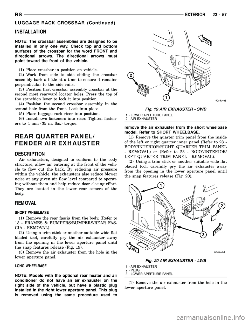
(2) Using a trim stick or another suitable wide flat
bladed tool, carefully pry the air exhauster away
from the opening in the lower aperture panel until
the snap features release (Fig. 19).
(3) Remove the air exhauster from the hole in the
lower aperture panel.
LONG WHEELBASE
NOTE: Models with the optional rear heater and air
conditioner do not have an air exhauster on the
right side of the vehicle, but have a plastic plug
installed in the right lower aperture panel. This plug
is removed using the same procedure used toremove the air exhauster from the short wheelbase
model. Refer to SHORT WHEELBASE.
(1) Remove the quarter trim panel from the inside
of the left or right quarter inner panel (Refer to 23 -
BODY/INTERIOR/RIGHT QUARTER TRIM PANEL
- REMOVAL) or (Refer to 23 - BODY/INTERIOR/
LEFT QUARTER TRIM PANEL - REMOVAL).
(2) Using a trim stick or another suitable wide flat
bladed tool, carefully pry the air exhauster away
from the opening in the lower aperture panel until
the snap features release (Fig. 20).
(1) Remove the air exhauster from the hole in the
lower aperture panel.
Fig. 19 AIR EXHAUSTER - SWB
1 - LOWER APERTURE PANEL
2 - AIR EXHAUSTER
Fig. 20 AIR EXHAUSTER - LWB
1 - AIR EXHAUSTER
2 - PLUG
3 - LOWER APERTURE PANEL
RSEXTERIOR23-57
LUGGAGE RACK CROSSBAR (Continued)