2004 CHRYSLER VOYAGER 8e electrical control module
[x] Cancel search: 8e electrical control modulePage 2027 of 2585
41TE AUTOMATIC TRANSAXLE
TABLE OF CONTENTS
page page
41TE AUTOMATIC TRANSAXLE DISASSEMBLY ........................166
ASSEMBLY ...........................184
ACCUMULATOR DESCRIPTION ........................206 VALVE BODY
REMOVAL ............................206
DISASSEMBLY ........................208
ASSEMBLY ...........................212
INSTALLATION ........................217
41TE AUTOMATIC
TRANSAXLE
DISASSEMBLY
NOTE: If transaxle is being overhauled (clutch and/or
seal replacement) or replaced, it is necessary to per-
form the PCM/TCM Quick Learn Procedure. (Refer to 8 -
ELECTRICAL/ELECTRONIC CONTROL MODULES/POW-
ERTRAIN/TRANSMISSION CONTROL MODULE - STAN-
DARD PROCEDURE)
NOTE: This procedure does not include final drive
(differential) disassembly.
(1) Remove input and output speed sensors.
(2) Remove three (3) solenoid/pressure switch
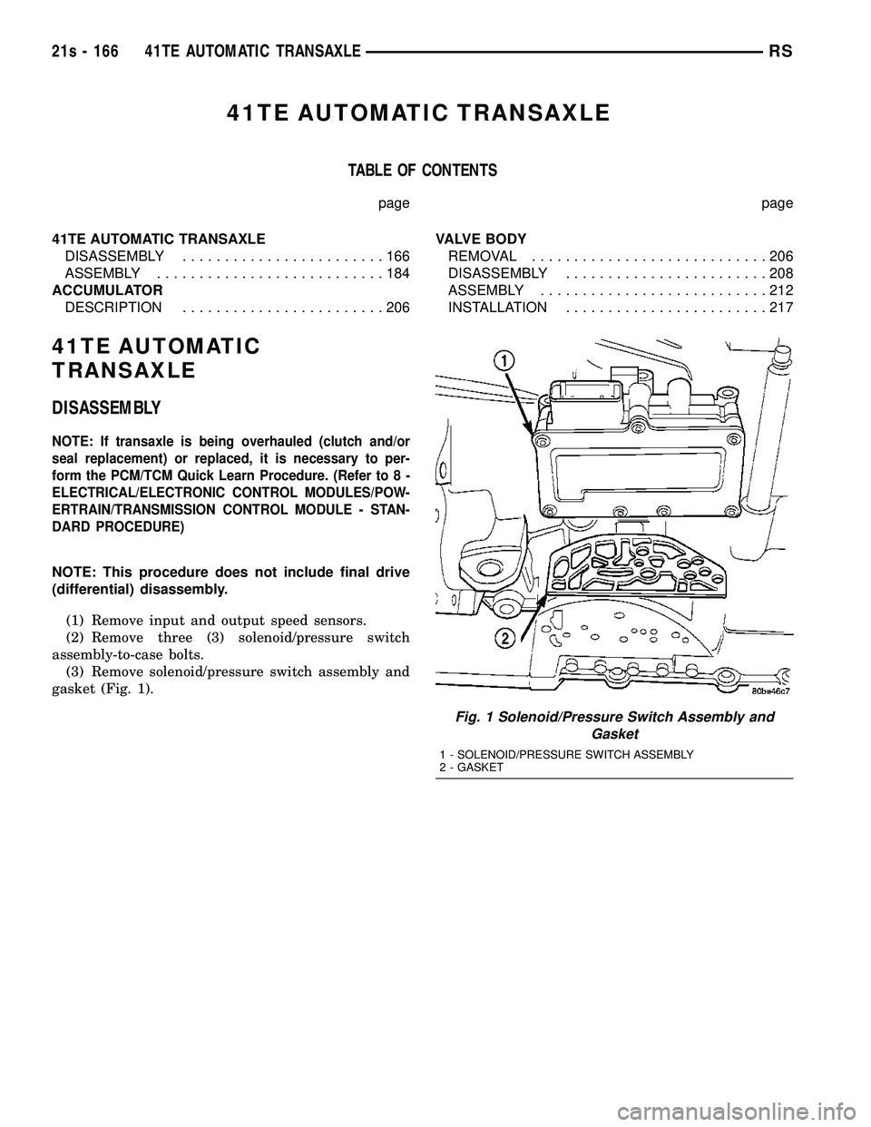
assembly-to-case bolts. (3) Remove solenoid/pressure switch assembly and
gasket (Fig. 1).
Fig. 1 Solenoid/Pressure Switch Assembly and Gasket
1 - SOLENOID/PRESSURE SWITCH ASSEMBLY
2 - GASKET
21s - 166 41TE AUTOMATIC TRANSAXLERS
Page 2067 of 2585
ACCUMULATOR
DESCRIPTION
The 4XTE underdrive, overdrive, low/reverse, and 2/4
clutch hydraulic circuits each contain an accumulator.
An accumulator typically consists of a piston, return
spring(s), and a cover or plug. The overdrive and under-
drive accumulators are located within the transaxle
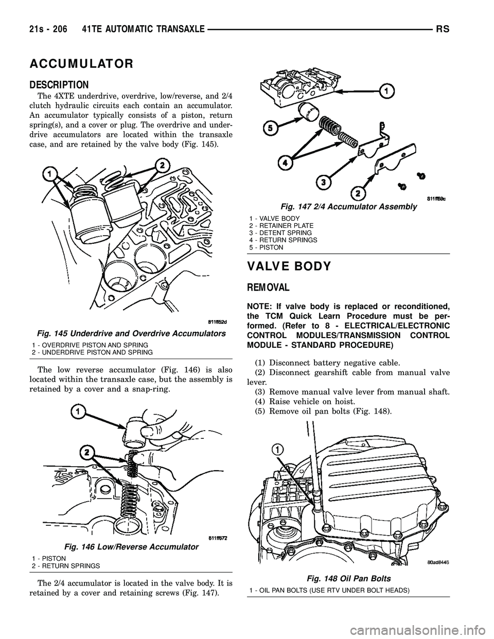
case, and are retained by the valve body (Fig. 145).
The low reverse accumulator (Fig. 146) is also
located within the transaxle case, but the assembly is
retained by a cover and a snap-ring.
The 2/4 accumulator is located in the valve body. It is
retained by a cover and retaining screws (Fig. 147).
VALVE BODY
REMOVAL
NOTE: If valve body is replaced or reconditioned,
the TCM Quick Learn Procedure must be per-
formed. (Refer t o 8 - ELECTRICAL/ELECTRONIC
CONTROL MODULES/TRANSMISSION CONTROL
MODULE - STANDARD PROCEDURE)
(1) Disconnect battery negative cable.
(2) Disconnect gearshift cable from manual valve
lever. (3) Remove manual valve lever from manual shaft.
(4) Raise vehicle on hoist.
(5) Remove oil pan bolts (Fig. 148).
Fig. 145 Underdrive and Overdrive Accumulators
1 - OVERDRIVE PISTON AND SPRING
2 - UNDERDRIVE PISTON AND SPRING
Fig. 146 Low/Reverse Accumulator
1 - PISTON
2 - RETURN SPRINGS
Fig. 147 2/4 Accumulator Assembly
1 - VALVE BODY
2 - RETAINER PLATE
3 - DETENT SPRING
4 - RETURN SPRINGS
5 - PISTON
Fig. 148 Oil Pan Bolts
1 - OIL PAN BOLTS (USE RTV UNDER BOLT HEADS)
21s - 206 41TE AUTOMATIC TRANSAXLERS
Page 2069 of 2585
CAUTION: The valve body manual shaft pilot may
distort and bind the manual valve if the valve body
is mishandled or dropped.
DISASSEMBLY
NOTE: If valve body assembly is being recondi-
tioned, the PCM/TCM Quick Learn Procedure must
be performed. (Refer to 8 - ELECTRICAL/ELEC-
TRONIC CONTROL MODULES/TRANSMISSION
CONTROL MODULE - STANDARD PROCEDURE)
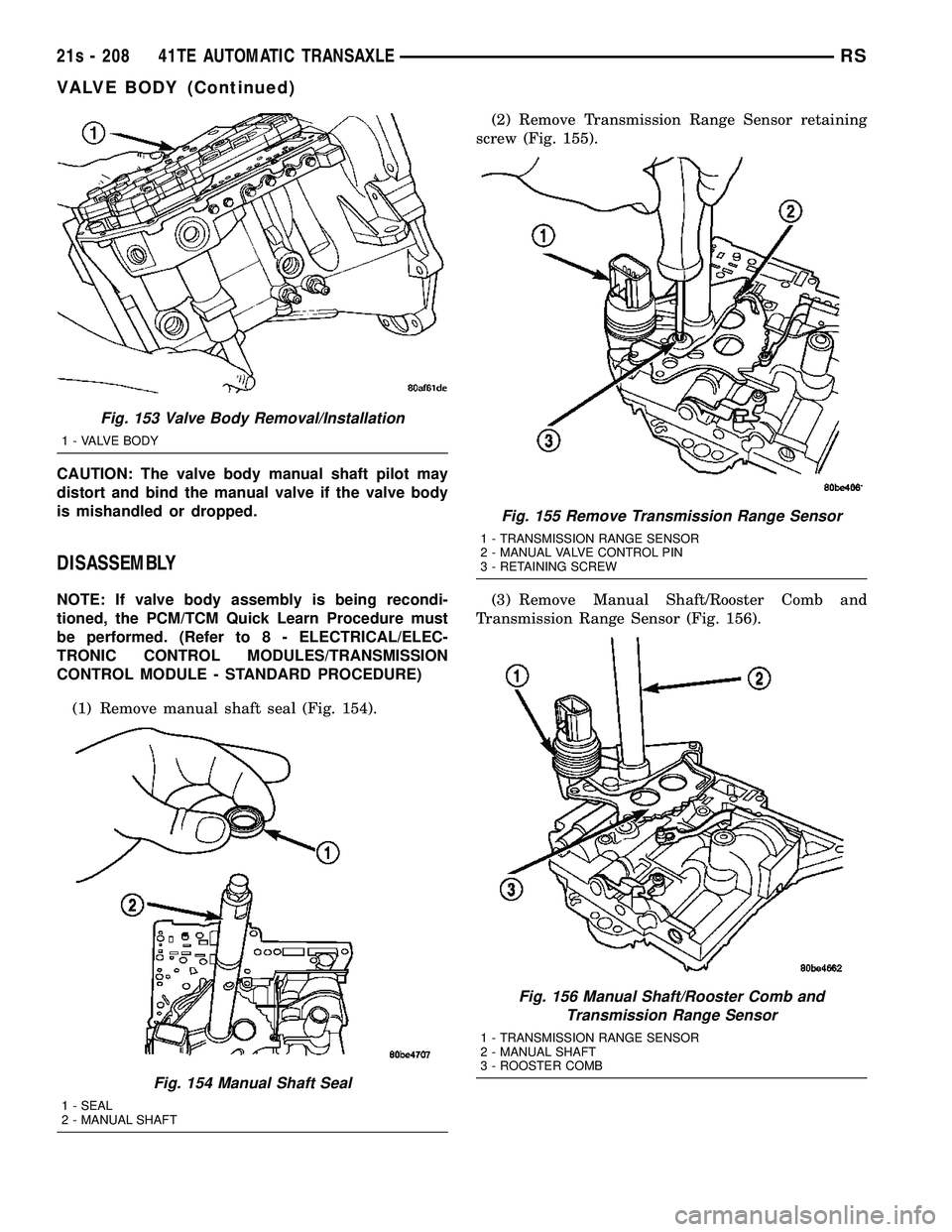
(1) Remove manual shaft seal (Fig. 154). (2) Remove Transmission Range Sensor retaining
screw (Fig. 155).
(3) Remove Manual Shaft/Rooster Comb and
Transmission Range Sensor (Fig. 156).
Fig. 153 Valve Body Removal/Installation
1 - VALVE BODY
Fig. 154 Manual Shaft Seal
1 - SEAL
2 - MANUAL SHAFT
Fig. 155 Remove Transmission Range Sensor
1 - TRANSMISSION RANGE SENSOR
2 - MANUAL VALVE CONTROL PIN
3 - RETAINING SCREW
Fig. 156 Manual Shaft/Rooster Comb and Transmission Range Sensor
1 - TRANSMISSION RANGE SENSOR
2 - MANUAL SHAFT
3 - ROOSTER COMB
21s - 208 41TE AUTOMATIC TRANSAXLERS
VALVE BODY (Continued)
Page 2073 of 2585

(14) Remove regulator valve spring retainer (Fig.
167).
(15) Remove remaining retainers as shown in (Fig.
168). (16) Remove valves and springs as shown in (Fig.
169).
NOTE: Refer to Valve Body Cleaning and Inspection
for cleaning procedures.
ASSEMBLY
NOTE: If valve body assembly is reconditioned, the
PCM/TCM Quick Learn Procedure must be per-
formed. (Refer t o 8 - ELECTRICAL/ELECTRONIC
CONTROL MODULES/TRANSMISSION CONTROL
MODULE - STANDARD PROCEDURE)
(1) Install valves and springs as shown in (Fig.
169). (2) Install regulator valve spring retainer (Fig.
170). (3) Install dual retainer plate using Tool 6301 (Fig.
171).
Fig. 167 Remove Regulator Valve Spring Retainer using Tool 6302
1 - TOOL 6302
2 - RETAINER
Fig. 168 Valve Retainer Location
1 - RETAINER
2 - RETAINER
21s - 212 41TE AUTOMATIC TRANSAXLERS
VALVE BODY (Continued)
Page 2078 of 2585
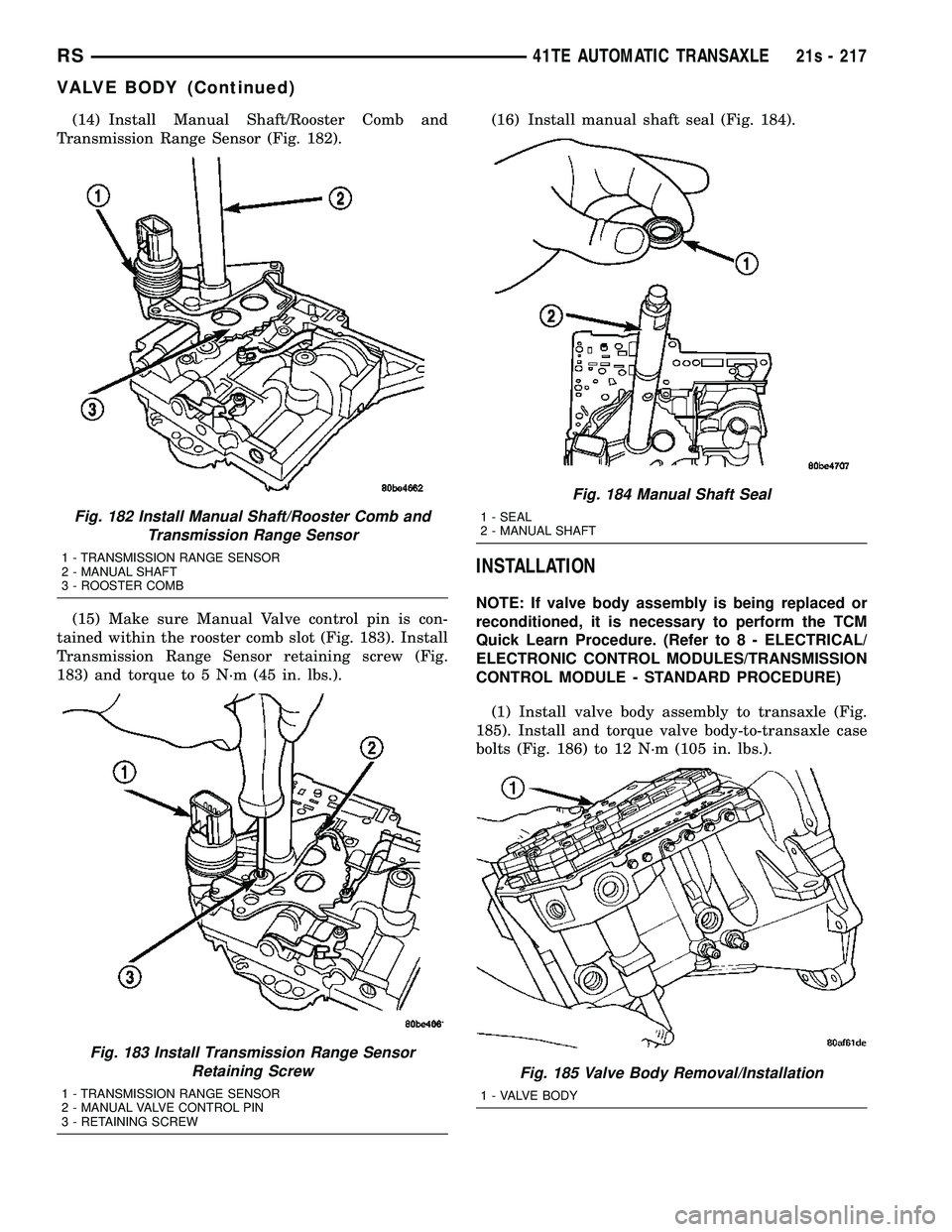
(14) Install Manual Shaft/Rooster Comb and
Transmission Range Sensor (Fig. 182).
(15) Make sure Manual Valve control pin is con-
tained within the rooster comb slot (Fig. 183). Install
Transmission Range Sensor retaining screw (Fig.
183) and torque to 5 N´m (45 in. lbs.). (16) Install manual shaft seal (Fig. 184).
INSTALLATION
NOTE: If valve body assembly is being replaced or
reconditioned, it is necessary to perform the TCM
Quick Learn Procedure. (Refer t
o 8 - ELECTRICAL/
ELECTRONIC CONTROL MODULES/TRANSMISSION
CONTROL MODULE - STANDARD PROCEDURE)
(1) Install valve body assembly to transaxle (Fig.
185). Install and torque valve body-to-transaxle case
bolts (Fig. 186) to 12 N´m (105 in. lbs.).
Fig. 182 Install Manual Shaft/Rooster Comb and Transmission Range Sensor
1 - TRANSMISSION RANGE SENSOR
2 - MANUAL SHAFT
3 - ROOSTER COMB
Fig. 183 Install Transmission Range Sensor Retaining Screw
1 - TRANSMISSION RANGE SENSOR
2 - MANUAL VALVE CONTROL PIN
3 - RETAINING SCREW
Fig. 184 Manual Shaft Seal
1 - SEAL
2 - MANUAL SHAFT
Fig. 185 Valve Body Removal/Installation
1 - VALVE BODY
RS 41TE AUTOMATIC TRANSAXLE21s - 217
VALVE BODY (Continued)
Page 2227 of 2585
SUNROOF
TABLE OF CONTENTS
page page
SUNROOF
DESCRIPTION........................116
DIAGNOSIS AND TESTING - SUNROOF.....116
DRAIN TUBE
REMOVAL............................119
INSTALLATION........................120
GLASS PANEL
REMOVAL............................120
INSTALLATION........................120
ADJUSTMENTS
SUNROOF GLASS PANEL ADJUSTMENT . . 120
SUNROOF ASSEMBLY
REMOVAL............................120
INSTALLATION........................120
SUNSHADE
REMOVAL............................120INSTALLATION........................121
WIND DEFLECTOR
REMOVAL............................121
INSTALLATION........................121
WATER CHANNEL
REMOVAL............................121
INSTALLATION........................121
SUNROOF MOTOR
REMOVAL............................121
INSTALLATION........................121
ADJUSTMENTS
ADJUSTMENT.......................122
SUNROOF SWITCH
REMOVAL............................123
INSTALLATION........................123
SUNROOF
DESCRIPTION
WARNING: Keep fingers and other body parts out
of sunroof opening at all times.
The sun roof features consists of: (Fig. 1)
²Sun roof glass
²Sun roof sun shade
The sunroof power sliding glass panel and sun-
shade can be positioned anywhere along its travel,
rearward of glass panel front edge.
The sunroof is electrically operated from a switch
located in the overhead console. To operate the sun-
roof the ignition switch must be in the Accessory or
On/Run position. Both switchs are a rocker style
design that open or close the sunroof. When pressing
and releasing the open button once, the sunroof will
express open to the comfort stop and the wind deflec-
tor will raise. If the button is pressed a second time,
the sunroof will continue to open to full travel unless
the button is released, at which time it will stop in
that position. Pressing and holding the close button
will close the sunroof. If the close button is released
before the glass fully closes, the sunroof will stop in
that position. The vent switch operates in a similar
manor. The sunroof will also operate for up to fifteenminutes after the ignition key is turned off for cus-
tomer comfort and convenance while parking.
DIAGNOSIS AND TESTING - SUNROOF
Refer to Sunroof Diagnostic Chart for possible
causes. Before beginning sunroof diagnostics verify
that all other power accessories are in proper operat-
ing condition. If not, a common electrical problem
may exist. Refer to Wiring Diagrams, in this publica-
tion for circuit, splice and component descriptions.
Check the condition of the circuit protection (20 amp
circuit breaker in the Junction Block). Inspect all
wiring connector pins for proper engagement and
continuity. Check for battery voltage at the power
sunroof controller, refer to Wiring Diagrams, for cir-
cuit information. If battery voltage of more than 10
volts is detected at the controller, proceed with the
following tests (the controller will not operate at less
than 10 volts).
Before beginning diagnosis for wind noise or water
leaks, verify that the problem was not caused by
releasing the control switch before the sunroof was
fully closed. The sunroof module has a water-man-
agement system. If however, the sunroof glass is in a
partial closed position, high pressure water may be
forced beyond the water management system bound-
aries and onto the headlining.
23 - 116 SUNROOFRS
Page 2410 of 2585
A/C COMPRESSOR CLUTCH/
COIL
DESCRIPTION
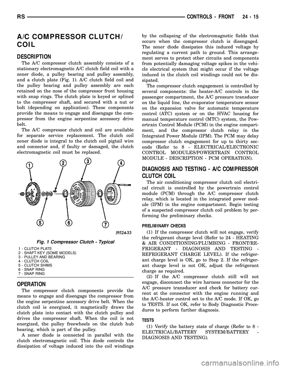
The A/C compressor clutch assembly consists of a
stationary electromagnetic A/C clutch field coil with a
zener diode, a pulley bearing and pulley assembly,
and a clutch plate (Fig. 1). A/C clutch field coil and
the pulley bearing and pulley assembly are each
retained on the nose of the compressor front housing
with snap rings. The clutch plate is keyed or splined
to the compressor shaft, and secured with a nut or
bolt (depending on application). These components
provide the means to engage and disengage the com-
pressor from the engine serpentine accessory drive
belt.
The A/C compressor clutch and coil are available
for separate service replacement. The clutch coil
zener diode is integral to the clutch coil pigtail wire
and connector and, if faulty or damaged, the clutch
electromagnetic coil must be replaced.
OPERATION
The compressor clutch components provide the
means to engage and disengage the compressor from
the engine serpentine accessory drive belt. When the
clutch coil is energized, it magnetically draws the
clutch plate into contact with the clutch pulley and
drives the compressor shaft. When the coil is not
energized, the pulley freewheels on the clutch hub
bearing, which is part of the pulley.
A zener diode is connected in parallel with the
clutch electromagnetic coil. This diode controls the
dissipation of voltage induced into the coil windingsby the collapsing of the electromagnetic fields that
occurs when the compressor clutch is disengaged.
The zener diode dissipates this induced voltage by
regulating a current path to ground. This arrange-
ment serves to protect other circuits and components
from potentially damaging voltage spikes in the vehi-
cle electrical system that might occur if the voltage
induced in the clutch coil windings could not be dis-
sipated.
The compressor clutch engagement is controlled by
several components: the heater-A/C controls in the
passenger compartment, the A/C pressure transducer
on the liquid line, the evaporator temperature sensor
on the expansion valve for automatic temperature
control (ATC) system or on the HVAC housing for
manual temperature control (MTC) system, the Pow-
ertrain Control Module (PCM) in the engine compart-
ment, and the compressor clutch relay in the
Integrated Power Module (IPM). The PCM may delay
compressor clutch engagement for up to thirty sec-
onds (Refer to 8 - ELECTRICAL/ELECTRONIC
CONTROL MODULES/POWERTRAIN CONTROL
MODULE - DESCRIPTION - PCM OPERATION).
DIAGNOSIS AND TESTING - A/C COMPRESSOR
CLUTCH COIL
The air conditioning compressor clutch coil electri-
cal circuit is controlled by the powertrain control
module (PCM) through the A/C compressor clutch
relay, which is located in the integrated power mod-
ule (IPM) in the engine compartment. Begin testing
of a suspected compressor clutch coil problem by per-
forming the preliminary checks.
PRELIMINARY CHECKS
(1) If the compressor clutch will not engage, verify
the refrigerant charge level (Refer to 24 - HEATING
& AIR CONDITIONING/PLUMBING - FRONT/RE-
FRIGERANT - DIAGNOSIS AND TESTING -
REFRIGERANT CHARGE LEVEL). If the refriger-
ant charge level is OK, go to Step 2. If the refriger-
ant charge level is not OK, adjust the refrigerant
charge as required.
(2) If the A/C compressor clutch still will not
engage, disconnect the wire harness connector for the
A/C pressure transducer and check for battery cur-
rent at the connector with the engine running and
the A/C-heater control set to the A/C mode. If OK, go
to TESTS. If not OK, refer to Body Diagnostic Proce-
dures to perform further diagnosis.
TESTS
(1) Verify the battery state of charge (Refer to 8 -
ELECTRICAL/BATTERY SYSTEM/BATTERY -
DIAGNOSIS AND TESTING).
Fig. 1 Compressor Clutch - Typical
1 - CLUTCH PLATE
2 - SHAFT KEY (SOME MODELS)
3 - PULLEY AND BEARING
4 - CLUTCH COIL
5 - CLUTCH SHIMS
6 - SNAP RING
7 - SNAP RING
RSCONTROLS - FRONT24-15
Page 2414 of 2585
COOLING/ACCESSORY DRIVE/DRIVE BELTS -
3.3L/3.8L - INSTALLATION).
(15) Lower the vehicle.
(16) Reconnect the battery negative cable.
CLUTCH BREAK-IN
After a new compressor clutch has been installed,
cycle the compressor clutch approximately twenty
times (five seconds on, then five seconds off). During
this procedure, set the A/C-heater control to the A/C
Recirculation Mode, the blower motor switch in the
highest speed position, and the engine speed at 1500
to 2000 rpm. This procedure (burnishing) will seat
the opposing friction surfaces and provide a higher
compressor clutch torque capability.
A/C COMPRESSOR CLUTCH
RELAY
DESCRIPTION
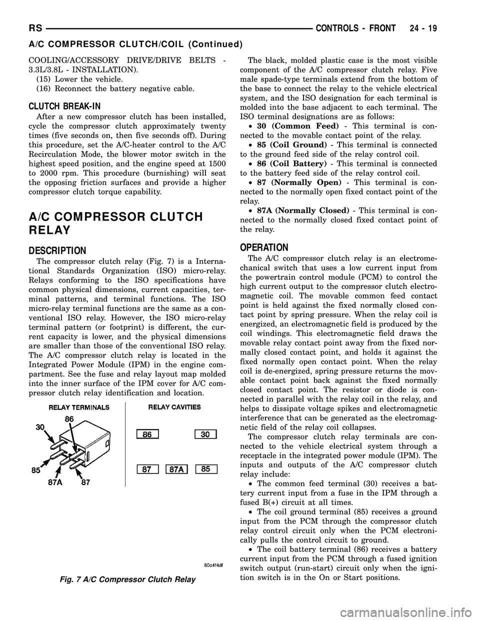
The compressor clutch relay (Fig. 7) is a Interna-
tional Standards Organization (ISO) micro-relay.
Relays conforming to the ISO specifications have
common physical dimensions, current capacities, ter-
minal patterns, and terminal functions. The ISO
micro-relay terminal functions are the same as a con-
ventional ISO relay. However, the ISO micro-relay
terminal pattern (or footprint) is different, the cur-
rent capacity is lower, and the physical dimensions
are smaller than those of the conventional ISO relay.
The A/C compressor clutch relay is located in the
Integrated Power Module (IPM) in the engine com-
partment. See the fuse and relay layout map molded
into the inner surface of the IPM cover for A/C com-
pressor clutch relay identification and location.The black, molded plastic case is the most visible
component of the A/C compressor clutch relay. Five
male spade-type terminals extend from the bottom of
the base to connect the relay to the vehicle electrical
system, and the ISO designation for each terminal is
molded into the base adjacent to each terminal. The
ISO terminal designations are as follows:
²30 (Common Feed)- This terminal is con-
nected to the movable contact point of the relay.
²85 (Coil Ground)- This terminal is connected
to the ground feed side of the relay control coil.
²86 (Coil Battery)- This terminal is connected
to the battery feed side of the relay control coil.
²87 (Normally Open)- This terminal is con-
nected to the normally open fixed contact point of the
relay.
²87A (Normally Closed)- This terminal is con-
nected to the normally closed fixed contact point of
the relay.
OPERATION
The A/C compressor clutch relay is an electrome-
chanical switch that uses a low current input from
the powertrain control module (PCM) to control the
high current output to the compressor clutch electro-
magnetic coil. The movable common feed contact
point is held against the fixed normally closed con-
tact point by spring pressure. When the relay coil is
energized, an electromagnetic field is produced by the
coil windings. This electromagnetic field draws the
movable relay contact point away from the fixed nor-
mally closed contact point, and holds it against the
fixed normally open contact point. When the relay
coil is de-energized, spring pressure returns the mov-
able contact point back against the fixed normally
closed contact point. The resistor or diode is con-
nected in parallel with the relay coil in the relay, and
helps to dissipate voltage spikes and electromagnetic
interference that can be generated as the electromag-
netic field of the relay coil collapses.
The compressor clutch relay terminals are con-
nected to the vehicle electrical system through a
receptacle in the integrated power module (IPM). The
inputs and outputs of the A/C compressor clutch
relay include:
²The common feed terminal (30) receives a bat-
tery current input from a fuse in the IPM through a
fused B(+) circuit at all times.
²The coil ground terminal (85) receives a ground
input from the PCM through the compressor clutch
relay control circuit only when the PCM electroni-
cally pulls the control circuit to ground.
²The coil battery terminal (86) receives a battery
current input from the PCM through a fused ignition
switch output (run-start) circuit only when the igni-
tion switch is in the On or Start positions.
Fig. 7 A/C Compressor Clutch Relay
RSCONTROLS - FRONT24-19
A/C COMPRESSOR CLUTCH/COIL (Continued)