2004 CHRYSLER VOYAGER 8e electrical control module
[x] Cancel search: 8e electrical control modulePage 1845 of 2585
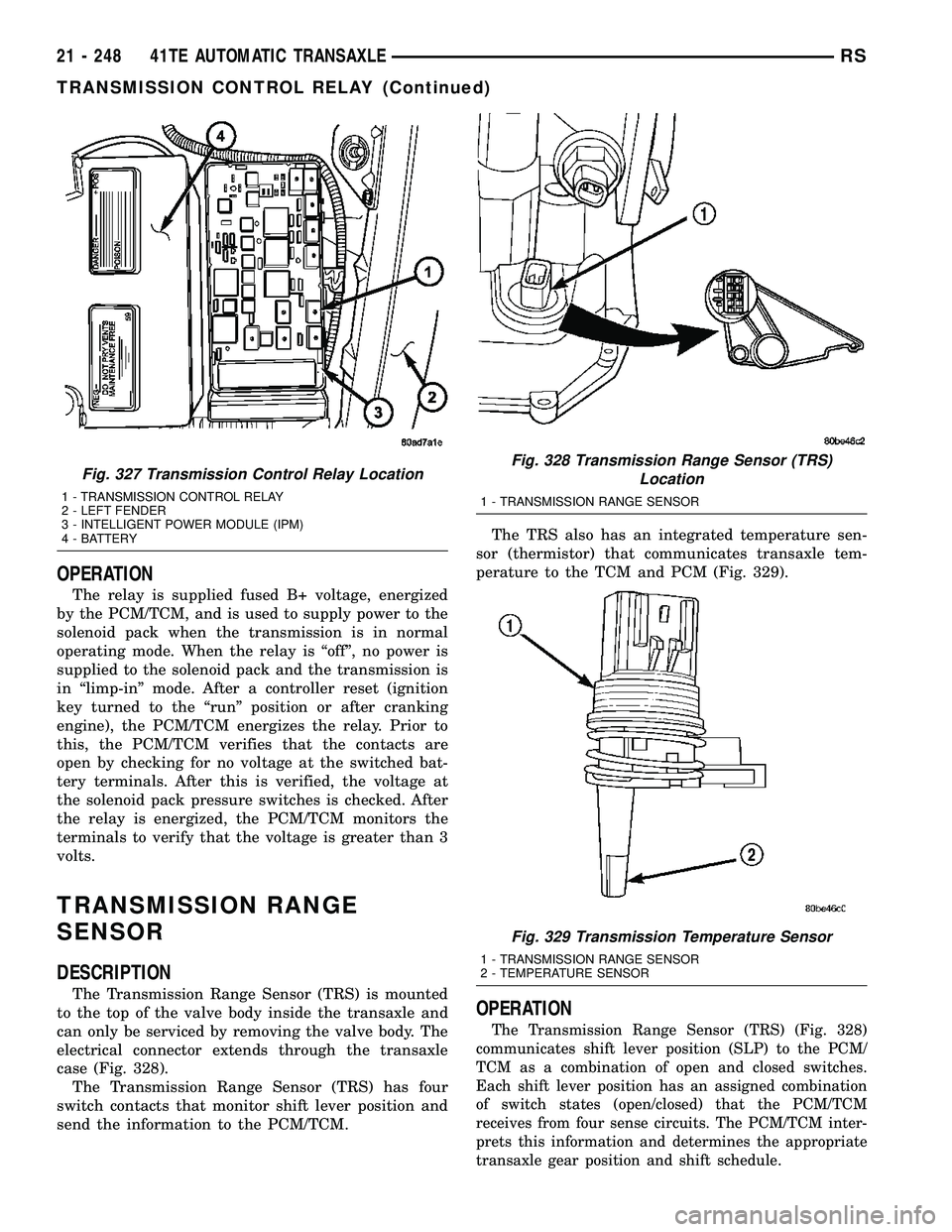
OPERATION
The relay is supplied fused B+ voltage, energized
by the PCM/TCM, and is used to supply power to the
solenoid pack when the transmission is in normal
operating mode. When the relay is ªoffº, no power is
supplied to the solenoid pack and the transmission is
in ªlimp-inº mode. After a controller reset (ignition
key turned to the ªrunº position or after cranking
engine), the PCM/TCM energizes the relay. Prior to
this, the PCM/TCM verifies that the contacts are
open by checking for no voltage at the switched bat-
tery terminals. After this is verified, the voltage at
the solenoid pack pressure switches is checked. After
the relay is energized, the PCM/TCM monitors the
terminals to verify that the voltage is greater than 3
volts.
TRANSMISSION RANGE
SENSOR
DESCRIPTION
The Transmission Range Sensor (TRS) is mounted
to the top of the valve body inside the transaxle and
can only be serviced by removing the valve body. The
electrical connector extends through the transaxle
case (Fig. 328).
The Transmission Range Sensor (TRS) has four
switch contacts that monitor shift lever position and
send the information to the PCM/TCM.The TRS also has an integrated temperature sen-
sor (thermistor) that communicates transaxle tem-
perature to the TCM and PCM (Fig. 329).
OPERATION
The Transmission Range Sensor (TRS) (Fig. 328)
communicates shift lever position (SLP) to the PCM/
TCM as a combination of open and closed switches.
Each shift lever position has an assigned combination
of switch states (open/closed) that the PCM/TCM
receives from four sense circuits. The PCM/TCM inter-
prets this information and determines the appropriate
transaxle gear position and shift schedule.
Fig. 327 Transmission Control Relay Location
1 - TRANSMISSION CONTROL RELAY
2 - LEFT FENDER
3 - INTELLIGENT POWER MODULE (IPM)
4 - BATTERY
Fig. 328 Transmission Range Sensor (TRS)
Location
1 - TRANSMISSION RANGE SENSOR
Fig. 329 Transmission Temperature Sensor
1 - TRANSMISSION RANGE SENSOR
2 - TEMPERATURE SENSOR
21 - 248 41TE AUTOMATIC TRANSAXLERS
TRANSMISSION CONTROL RELAY (Continued)
Page 1848 of 2585
MANUAL VALVE
The manual valve is operated by the mechanical
shift linkage. Its primary responsibility is to send
line pressure to the appropriate hydraulic circuits
and solenoids. The valve has three operating ranges
or positions.
CONVERTER CLUTCH SWITCH VALVE
The main responsibility of the converter clutch
switch valve is to control hydraulic pressure applied
to the front (off) side of the converter clutch piston.
Line pressure from the regulator valve is fed to the
torque converter regulator valve, where it passes
through the valve, and is slightly regulated. The
pressure is then directed to the converter clutch
switch valve and to the front side of the converter
clutch piston. This pressure pushes the piston back
and disengages the converter clutch.
CONVERTER CLUTCH CONTROL VALVE
The converter clutch control valve controls the
back (on) side of the torque converter clutch. When
the PCM/TCM energizes or modulates the LR/CC
solenoid to apply the converter clutch piston, both
the converter clutch control valve and the converter
control valve move, allowing pressure to be applied to
the back side of the clutch.
T/C REGULATOR VALVE
The torque converter regulator valve slightly regu-
lates the flow of fluid to the torque converter.
LOW/REVERSE SWITCH VALVE
The low/reverse clutch is applied from different
sources, depending on whether low (1st) gear or
reverse is selected. The low/reverse switch valve
alternates positions depending on from which direc-
tion fluid pressure is applied. By design, when the
valve is shifted by fluid pressure from one channel,
the opposing channel is blocked. The switch valve
alienates the possibility of a sticking ball check, thus
providing consistent application of the low/reverse
clutch under all operating conditions.
REMOVAL
NOTE: If valve body is replaced or reconditioned,
the TCM Quick Learn Procedure must be per-
formed. (Refer to 8 - ELECTRICAL/ELECTRONIC
CONTROL MODULES/TRANSMISSION CONTROL
MODULE - STANDARD PROCEDURE)(1) Disconnect battery negative cable.
(2) Disconnect gearshift cable from manual valve
lever.
(3) Remove manual valve lever from manual shaft.
(4) Raise vehicle on hoist.
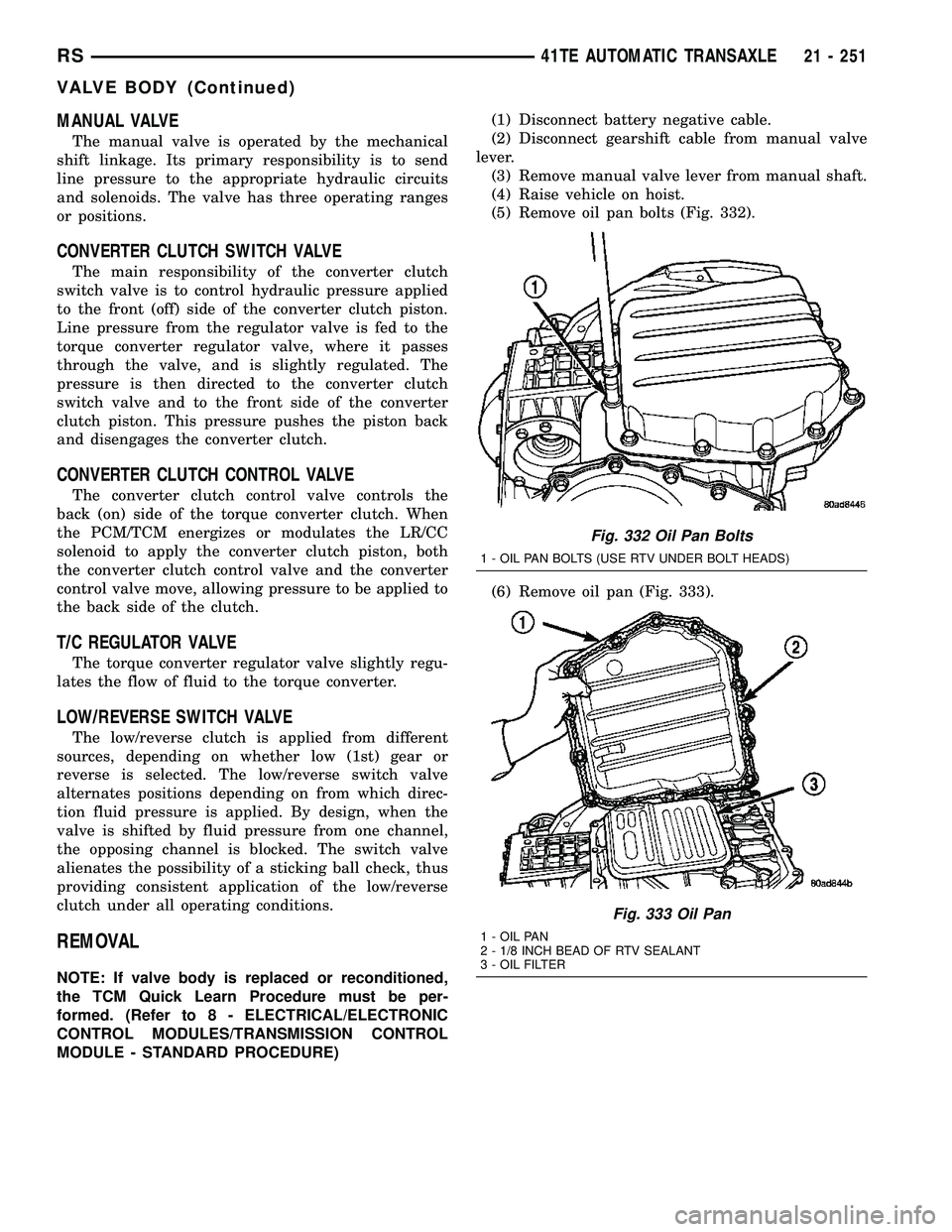
(5) Remove oil pan bolts (Fig. 332).
(6) Remove oil pan (Fig. 333).
Fig. 332 Oil Pan Bolts
1 - OIL PAN BOLTS (USE RTV UNDER BOLT HEADS)
Fig. 333 Oil Pan
1 - OIL PAN
2 - 1/8 INCH BEAD OF RTV SEALANT
3 - OIL FILTER
RS41TE AUTOMATIC TRANSAXLE21 - 251
VALVE BODY (Continued)
Page 1849 of 2585
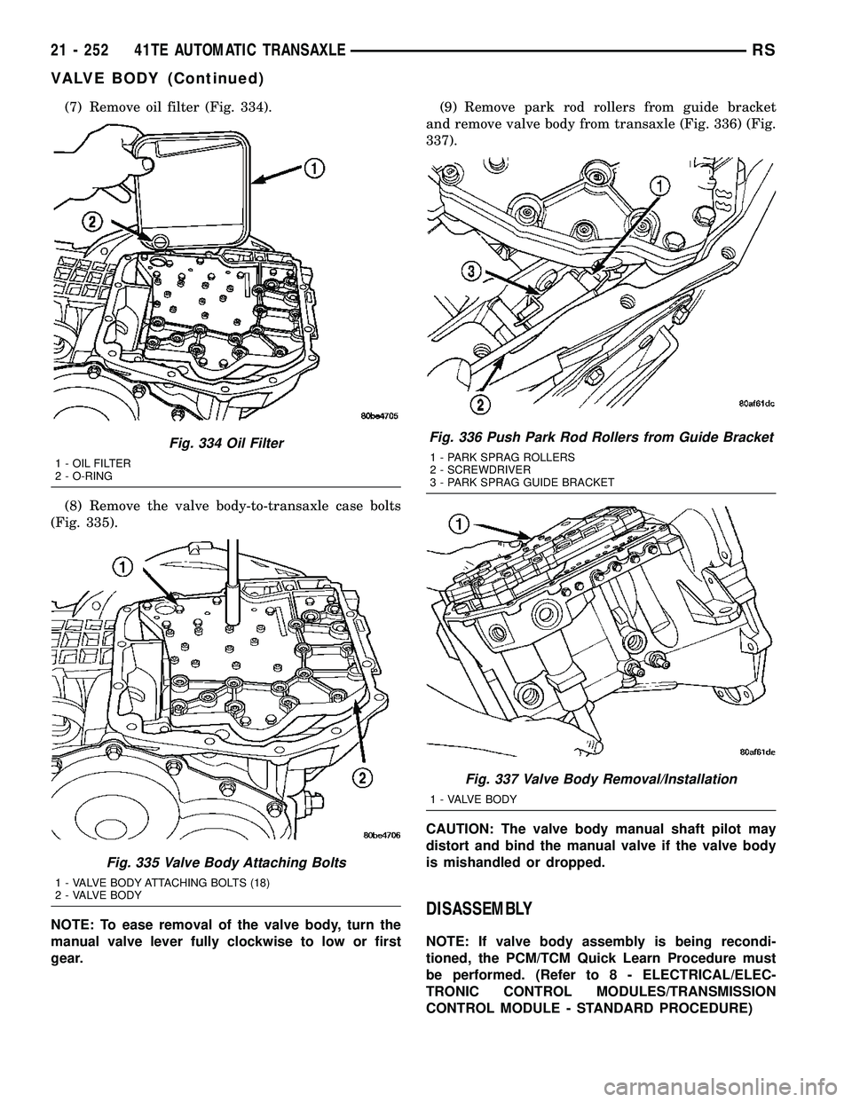
(7) Remove oil filter (Fig. 334).
(8) Remove the valve body-to-transaxle case bolts
(Fig. 335).
NOTE: To ease removal of the valve body, turn the
manual valve lever fully clockwise to low or first
gear.(9) Remove park rod rollers from guide bracket
and remove valve body from transaxle (Fig. 336) (Fig.
337).
CAUTION: The valve body manual shaft pilot may
distort and bind the manual valve if the valve body
is mishandled or dropped.
DISASSEMBLY
NOTE: If valve body assembly is being recondi-
tioned, the PCM/TCM Quick Learn Procedure must
be performed. (Refer to 8 - ELECTRICAL/ELEC-
TRONIC CONTROL MODULES/TRANSMISSION
CONTROL MODULE - STANDARD PROCEDURE)
Fig. 334 Oil Filter
1 - OIL FILTER
2 - O-RING
Fig. 335 Valve Body Attaching Bolts
1 - VALVE BODY ATTACHING BOLTS (18)
2 - VALVE BODY
Fig. 336 Push Park Rod Rollers from Guide Bracket
1 - PARK SPRAG ROLLERS
2 - SCREWDRIVER
3 - PARK SPRAG GUIDE BRACKET
Fig. 337 Valve Body Removal/Installation
1 - VALVE BODY
21 - 252 41TE AUTOMATIC TRANSAXLERS
VALVE BODY (Continued)
Page 1854 of 2585
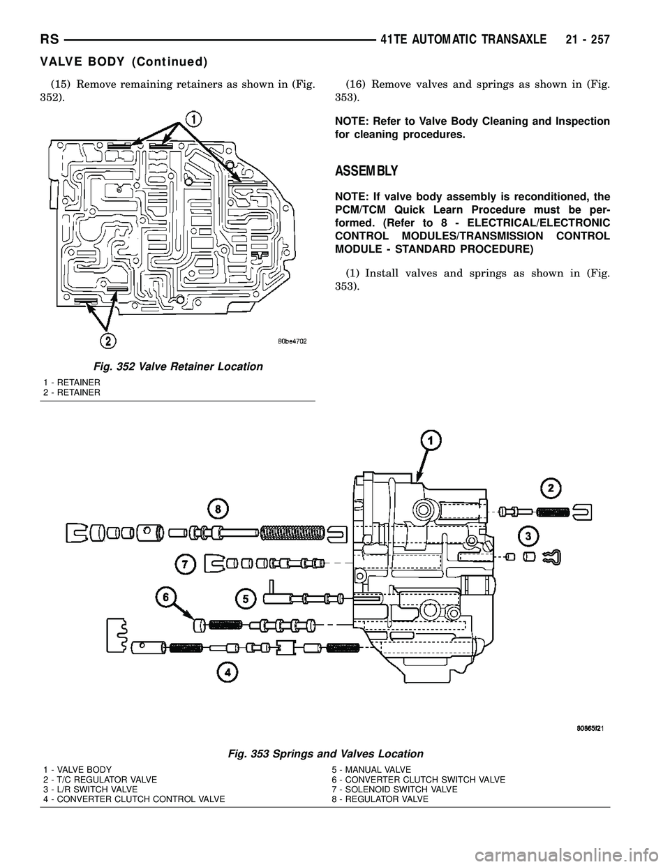
(15) Remove remaining retainers as shown in (Fig.
352).(16) Remove valves and springs as shown in (Fig.
353).
NOTE: Refer to Valve Body Cleaning and Inspection
for cleaning procedures.
ASSEMBLY
NOTE: If valve body assembly is reconditioned, the
PCM/TCM Quick Learn Procedure must be per-
formed. (Refer to 8 - ELECTRICAL/ELECTRONIC
CONTROL MODULES/TRANSMISSION CONTROL
MODULE - STANDARD PROCEDURE)
(1) Install valves and springs as shown in (Fig.
353).
Fig. 353 Springs and Valves Location
1 - VALVE BODY 5 - MANUAL VALVE
2 - T/C REGULATOR VALVE 6 - CONVERTER CLUTCH SWITCH VALVE
3 - L/R SWITCH VALVE 7 - SOLENOID SWITCH VALVE
4 - CONVERTER CLUTCH CONTROL VALVE 8 - REGULATOR VALVE
Fig. 352 Valve Retainer Location
1 - RETAINER
2 - RETAINER
RS41TE AUTOMATIC TRANSAXLE21 - 257
VALVE BODY (Continued)
Page 1859 of 2585
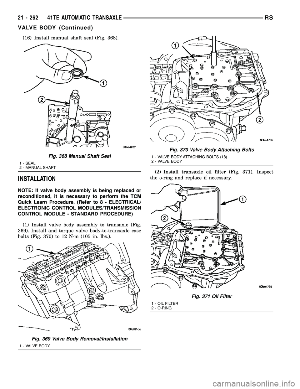
(16) Install manual shaft seal (Fig. 368).
INSTALLATION
NOTE: If valve body assembly is being replaced or
reconditioned, it is necessary to perform the TCM
Quick Learn Procedure. (Refer to 8 - ELECTRICAL/
ELECTRONIC CONTROL MODULES/TRANSMISSION
CONTROL MODULE - STANDARD PROCEDURE)
(1) Install valve body assembly to transaxle (Fig.
369). Install and torque valve body-to-transaxle case
bolts (Fig. 370) to 12 N´m (105 in. lbs.).(2) Install transaxle oil filter (Fig. 371). Inspect
the o-ring and replace if necessary.
Fig. 368 Manual Shaft Seal
1 - SEAL
2 - MANUAL SHAFT
Fig. 369 Valve Body Removal/Installation
1 - VALVE BODY
Fig. 370 Valve Body Attaching Bolts
1 - VALVE BODY ATTACHING BOLTS (18)
2 - VALVE BODY
Fig. 371 Oil Filter
1 - OIL FILTER
2 - O-RING
21 - 262 41TE AUTOMATIC TRANSAXLERS
VALVE BODY (Continued)
Page 1892 of 2585
DIAGNOSIS AND TESTING - TORQUE
CONVERTER HOUSING FLUID LEAKAGE
When diagnosing converter housing fluid leaks,
three actions must be taken before repair: (1) Verify proper transmission fluid level.
(2) Verify that the leak originates from the con-
verter housing area and is transmission fluid. (3) Determine the true source of the leak.
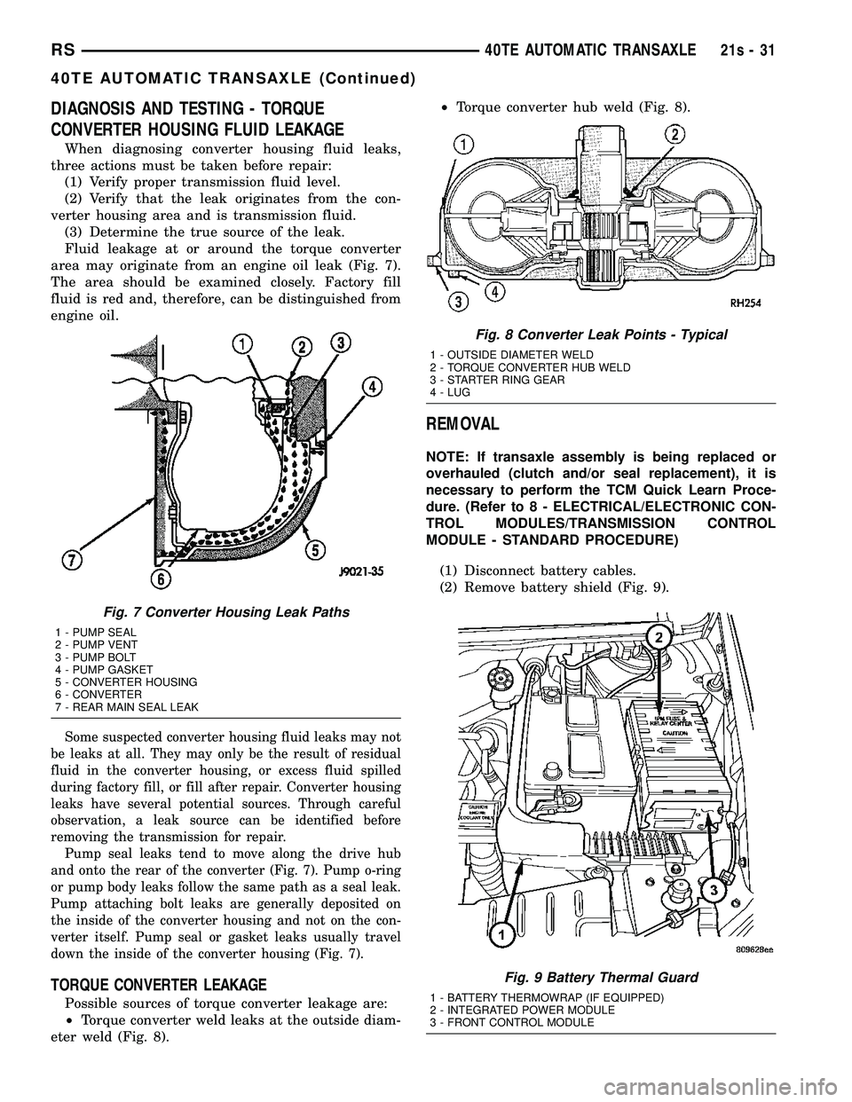
Fluid leakage at or around the torque converter
area may originate from an engine oil leak (Fig. 7).
The area should be examined closely. Factory fill
fluid is red and, therefore, can be distinguished from
engine oil.
Some suspected converter housing fluid leaks may not
be leaks at all. They may only be the result of residual
fluid in the converter housing, or excess fluid spilled
during factory fill, or fill after repair. Converter housing
leaks have several potential sources. Through careful
observation, a leak source can be identified before
removing the transmission for repair. Pump seal leaks tend to move along the drive hub
and onto the rear of the converter (Fig. 7). Pump o-ring
or pump body leaks follow the same path as a seal leak.
Pump attaching bolt leaks are generally deposited on
the inside of the converter housing and not on the con-
verter itself. Pump seal or gasket leaks usually travel
down the inside of the converter housing (Fig. 7).
TORQUE CONVERTER LEAKAGE
Possible sources of torque converter leakage are:
² Torque converter weld leaks at the outside diam-
eter weld (Fig. 8). ²
Torque converter hub weld (Fig. 8).
REMOVAL
NOTE: If transaxle assembly is being replaced or
overhauled (clutch and/or seal replacement), it is
necessary to perform the TCM Quick Learn Proce-
dure. (Refer t o 8 - ELECTRICAL/ELECTRONIC CON-
TROL MODULES/TRANSMISSION CONTROL
MODULE - STANDARD PROCEDURE)
(1) Disconnect battery cables.
(2) Remove battery shield (Fig. 9).
Fig. 7 Converter Housing Leak Paths
1 - PUMP SEAL
2 - PUMP VENT
3 - PUMP BOLT
4 - PUMP GASKET
5 - CONVERTER HOUSING
6 - CONVERTER
7 - REAR MAIN SEAL LEAK
Fig. 8 Converter Leak Points - Typical
1 - OUTSIDE DIAMETER WELD
2 - TORQUE CONVERTER HUB WELD
3 - STARTER RING GEAR
4 - LUG
Fig. 9 Battery Thermal Guard
1 - BATTERY THERMOWRAP (IF EQUIPPED)
2 - INTEGRATED POWER MODULE
3 - FRONT CONTROL MODULE
RS 40TE AUTOMATIC TRANSAXLE21s-31
40TE AUTOMATIC TRANSAXLE (Continued)
Page 1895 of 2585
(27) Lower engine/transaxle assembly with screw
jack. (28) Obtain helper and/or transmission jack.
Secure transmission jack to transaxle assembly. (29) Remove upper mount bracket from transaxle
(Fig. 14). (30) Remove remaining transaxle bellhousing-to-
engine bolts. (31) Remove transaxle assembly from vehicle.
DISASSEMBLY
NOTE: If transaxle is being overhauled (clutch
and/or seal replacement) or replaced, it is neces-
sary to perform the PCM/TCM Quick Learn Proce-
dure. (Refer t o 8 - ELECTRICAL/ELECTRONIC
CONTROL MODULES/POWERTRAIN/TRANSMIS-
SION CONTROL MODULE - STANDARD PROCE-
DURE)
NOTE: This procedure does not include final drive
(differential) disassembly.
(1) Remove input and output speed sensors.
(2) Remove three (3) solenoid/pressure switch
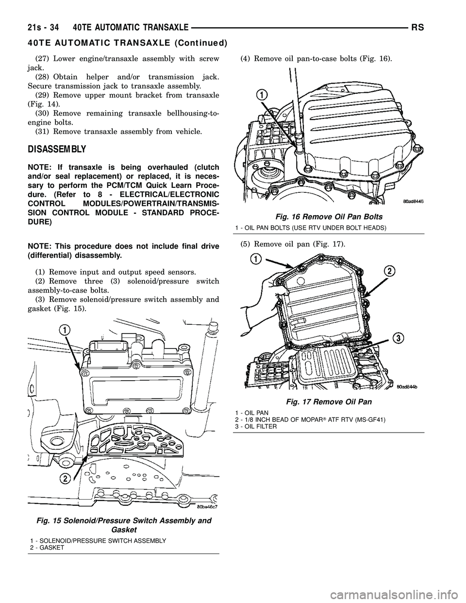
assembly-to-case bolts. (3) Remove solenoid/pressure switch assembly and
gasket (Fig. 15). (4) Remove oil pan-to-case bolts (Fig. 16).
(5) Remove oil pan (Fig. 17).
Fig. 15 Solenoid/Pressure Switch Assembly and
Gasket
1 - SOLENOID/PRESSURE SWITCH ASSEMBLY
2 - GASKET
Fig. 16 Remove Oil Pan Bolts
1 - OIL PAN BOLTS (USE RTV UNDER BOLT HEADS)
Fig. 17 Remove Oil Pan
1 - OIL PAN
2 - 1/8 INCH BEAD OF MOPAR TATF RTV (MS-GF41)
3 - OIL FILTER
21s - 34 40TE AUTOMATIC TRANSAXLERS
40TE AUTOMATIC TRANSAXLE (Continued)
Page 1912 of 2585
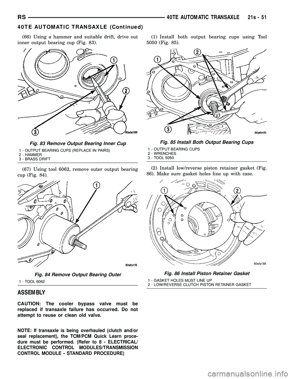
(66) Using a hammer and suitable drift, drive out
inner output bearing cup (Fig. 83).
(67) Using tool 6062, remove outer output bearing
cup (Fig. 84).
ASSEMBLY
CAUTION: The cooler bypass valve must be
replaced if transaxle failure has occurred. Do not
attempt to reuse or clean old valve.
NOTE: If transaxle is being overhauled (clutch and/or
seal replacement), the TCM/PCM Quick Learn proce-
dure must be performed. (Refer t o 8 - ELECTRICAL/
ELECTRONIC CONTROL MODULES/TRANSMISSION
CONTROL MODULE - STANDARD PROCEDURE)
(1) Install both output bearing cups using Tool
5050 (Fig. 85).
(2) Install low/reverse piston retainer gasket (Fig.
86). Make sure gasket holes line up with case.
Fig. 83 Remove Output Bearing Inner Cup
1 - OUTPUT BEARING CUPS (REPLACE IN PAIRS)
2 - HAMMER
3 - BRASS DRIFT
Fig. 84 Remove Output Bearing Outer
1 - TOOL 6062
Fig. 85 Install Both Output Bearing Cups
1 - OUTPUT BEARING CUPS
2 - WRENCHES
3 - TOOL 5050
Fig. 86 Install Piston Retainer Gasket
1 - GASKET HOLES MUST LINE UP
2 - LOW/REVERSE CLUTCH PISTON RETAINER GASKET
RS 40TE AUTOMATIC TRANSAXLE21s-51
40TE AUTOMATIC TRANSAXLE (Continued)