2004 CHRYSLER VOYAGER Ignition lock
[x] Cancel search: Ignition lockPage 1212 of 2585
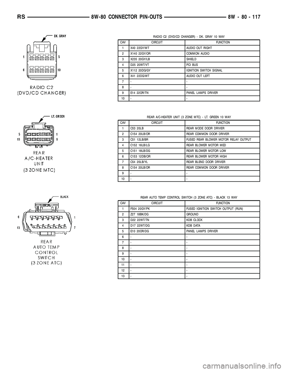
RADIO C2 (DVD/CD CHANGER) - DK. GRAY 10 WAY
CAV CIRCUIT FUNCTION
1 X40 22GY/WT AUDIO OUT RIGHT
2 X140 22GY/OR COMMON AUDIO
3 X235 20GY/LB SHIELD
4 D25 20WT/VT PCI BUS
5 X112 20DG/GY IGNITION SWITCH SIGNAL
6 X41 22DG/WT AUDIO OUT LEFT
7- -
8- -
9 E14 22OR/TN PANEL LAMPS DRIVER
10 - -
REAR A/C-HEATER UNIT (3 ZONE MTC) - LT. GREEN 10 WAY
CAV CIRCUIT FUNCTION
1 C53 20LB REAR MODE DOOR DRIVER
2 C154 20LB/OR REAR COMMON DOOR DRIVER
3 C51 12LB/BR FUSED REAR BLOWER MOTOR RELAY OUTPUT
4 C152 16LB/LG REAR BLOWER MOTOR MED
5 C151 18LB/DG REAR BLOWER MOTOR LOW
6 C153 12DB/OR REAR BLOWER MOTOR HIGH
7 C54 20LB/YL REAR BLEND DOOR DRIVER
8 C154 20LB/OR REAR COMMON DOOR DRIVER
9- -
10 - -
REAR AUTO TEMP CONTROL SWITCH (3 ZONE ATC) - BLACK 13 WAY
CAV CIRCUIT FUNCTION
1 F504 20GY/PK FUSED IGNITION SWITCH OUTPUT (RUN)
2 Z27 18BK/DG GROUND
3 D22 22WT/TN KDB CLOCK
4 D17 22WT/DG KDB DATA
5 E10 20OR/DG PANEL LAMPS DRIVER
6- -
7- -
8- -
9- -
10 - -
11 - -
12 - -
13 - -
RS8W-80 CONNECTOR PIN-OUTS8W - 80 - 117
Page 1237 of 2585
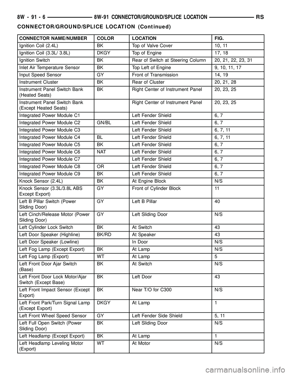
CONNECTOR NAME/NUMBER COLOR LOCATION FIG.
Ignition Coil (2.4L) BK Top of Valve Cover 10, 11
Ignition Coil (3.3L/ 3.8L) DKGY Top of Engine 17, 18
Ignition Switch BK Rear of Switch at Steering Column 20, 21, 22, 23, 31
Inlet Air Temperature Sensor BK Top Left of Engine 9, 10, 11, 17
Input Speed Sensor GY Front of Transmission 14, 19
Instrument Cluster BK Rear of Cluster 20, 21, 28
Instrument Panel Switch Bank
(Heated Seats)BK Right Center of Instrument Panel 20, 23, 25
Instrument Panel Switch Bank
(Except Heated Seats)Right Center of Instrument Panel 20, 23, 25
Integrated Power Module C1 Left Fender Shield 6, 7
Integrated Power Module C2 GN/BL Left Fender Shield 6, 7
Integrated Power Module C3 Left Fender Shield 6, 7, 11
Integrated Power Module C4 BL Left Fender Shield 6, 7, 11
Integrated Power Module C5 BK Left Fender Shield 6, 7
Integrated Power Module C6 NAT Left Fender Shield 6, 7
Integrated Power Module C7 Left Fender Shield 6, 7
Integrated Power Module C8 OR Left Fender Shield 6, 7
Integrated Power Module C9 BK Left Fender Shield 6, 7
Knock Sensor (2.4L) BK At Engine Block N/S
Knock Sensor (3.3L/3.8L ABS
Except Export)GY Front of Cylinder Block 11
Left B Pillar Switch (Power
Sliding Door)GY Left B Pillar 40
Left Cinch/Release Motor (Power
Sliding Door)GY Left Sliding Door N/S
Left Cylinder Lock Switch BK At Switch 43
Left Door Speaker (Highline) BK/RD At Speaker 43
Left Door Speaker (Lowline) In Door N/S
Left Fog Lamp (Except Export) BK At Lamp N/S
Left Fog Lamp (Export) WT At Lamp 5
Left Front Door Ajar Switch
(Base)BK At Switch N/S
Left Front Door Lock Motor/Ajar
Switch (Except Base)BK Left Door 43
Left Front Impact Sensor (Except
Export)BK Near T/O for C300 N/S
Left Front Park/Turn Signal Lamp
(Except Export)DKGY At Lamp 1
Left Front Wheel Speed Sensor GY Left Fender Side Shield 5, 11
Left Full Open Switch (Power
Sliding Door)BK Left Sliding Door N/S
Left Headlamp (Except Export) BK At Lamp 1
Left Headlamp Leveling Motor
(Export)WT At Motor N/S
8W - 91 - 6 8W-91 CONNECTOR/GROUND/SPLICE LOCATIONRS
CONNECTOR/GROUND/SPLICE LOCATION (Continued)
Page 1294 of 2585
INSTALLATION
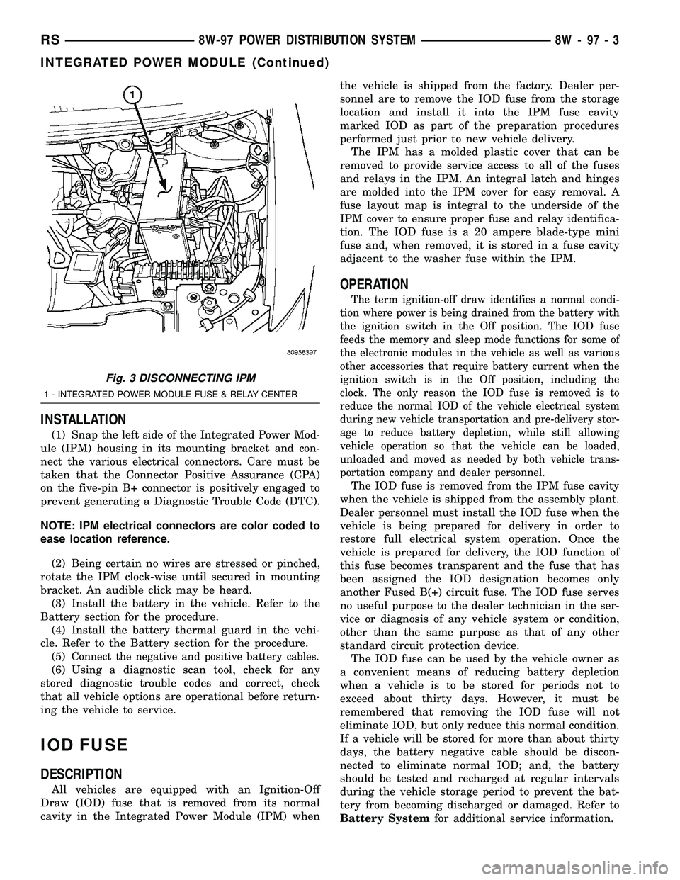
(1) Snap the left side of the Integrated Power Mod-
ule (IPM) housing in its mounting bracket and con-
nect the various electrical connectors. Care must be
taken that the Connector Positive Assurance (CPA)
on the five-pin B+ connector is positively engaged to
prevent generating a Diagnostic Trouble Code (DTC).
NOTE: IPM electrical connectors are color coded to
ease location reference.
(2) Being certain no wires are stressed or pinched,
rotate the IPM clock-wise until secured in mounting
bracket. An audible click may be heard.
(3) Install the battery in the vehicle. Refer to the
Battery section for the procedure.
(4) Install the battery thermal guard in the vehi-
cle. Refer to the Battery section for the procedure.
(5)
Connect the negative and positive battery cables.
(6) Using a diagnostic scan tool, check for any
stored diagnostic trouble codes and correct, check
that all vehicle options are operational before return-
ing the vehicle to service.
IOD FUSE
DESCRIPTION
All vehicles are equipped with an Ignition-Off
Draw (IOD) fuse that is removed from its normal
cavity in the Integrated Power Module (IPM) whenthe vehicle is shipped from the factory. Dealer per-
sonnel are to remove the IOD fuse from the storage
location and install it into the IPM fuse cavity
marked IOD as part of the preparation procedures
performed just prior to new vehicle delivery.
The IPM has a molded plastic cover that can be
removed to provide service access to all of the fuses
and relays in the IPM. An integral latch and hinges
are molded into the IPM cover for easy removal. A
fuse layout map is integral to the underside of the
IPM cover to ensure proper fuse and relay identifica-
tion. The IOD fuse is a 20 ampere blade-type mini
fuse and, when removed, it is stored in a fuse cavity
adjacent to the washer fuse within the IPM.
OPERATION
The term ignition-off draw identifies a normal condi-
tion where power is being drained from the battery with
the ignition switch in the Off position. The IOD fuse
feeds the memory and sleep mode functions for some of
the electronic modules in the vehicle as well as various
other accessories that require battery current when the
ignition switch is in the Off position, including the
clock. The only reason the IOD fuse is removed is to
reduce the normal IOD of the vehicle electrical system
during new vehicle transportation and pre-delivery stor-
age to reduce battery depletion, while still allowing
vehicle operation so that the vehicle can be loaded,
unloaded and moved as needed by both vehicle trans-
portation company and dealer personnel.
The IOD fuse is removed from the IPM fuse cavity
when the vehicle is shipped from the assembly plant.
Dealer personnel must install the IOD fuse when the
vehicle is being prepared for delivery in order to
restore full electrical system operation. Once the
vehicle is prepared for delivery, the IOD function of
this fuse becomes transparent and the fuse that has
been assigned the IOD designation becomes only
another Fused B(+) circuit fuse. The IOD fuse serves
no useful purpose to the dealer technician in the ser-
vice or diagnosis of any vehicle system or condition,
other than the same purpose as that of any other
standard circuit protection device.
The IOD fuse can be used by the vehicle owner as
a convenient means of reducing battery depletion
when a vehicle is to be stored for periods not to
exceed about thirty days. However, it must be
remembered that removing the IOD fuse will not
eliminate IOD, but only reduce this normal condition.
If a vehicle will be stored for more than about thirty
days, the battery negative cable should be discon-
nected to eliminate normal IOD; and, the battery
should be tested and recharged at regular intervals
during the vehicle storage period to prevent the bat-
tery from becoming discharged or damaged. Refer to
Battery Systemfor additional service information.
Fig. 3 DISCONNECTING IPM
1 - INTEGRATED POWER MODULE FUSE & RELAY CENTER
RS8W-97 POWER DISTRIBUTION SYSTEM8W-97-3
INTEGRATED POWER MODULE (Continued)
Page 1324 of 2585
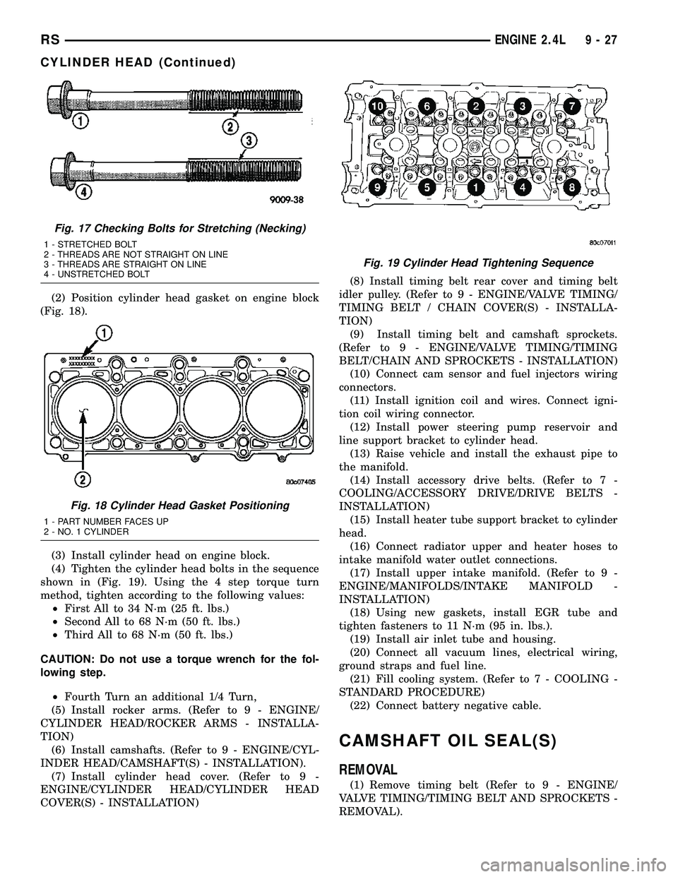
(2) Position cylinder head gasket on engine block
(Fig. 18).
(3) Install cylinder head on engine block.
(4) Tighten the cylinder head bolts in the sequence
shown in (Fig. 19). Using the 4 step torque turn
method, tighten according to the following values:
²First All to 34 N´m (25 ft. lbs.)
²Second All to 68 N´m (50 ft. lbs.)
²Third All to 68 N´m (50 ft. lbs.)
CAUTION: Do not use a torque wrench for the fol-
lowing step.
²Fourth Turn an additional 1/4 Turn,
(5) Install rocker arms. (Refer to 9 - ENGINE/
CYLINDER HEAD/ROCKER ARMS - INSTALLA-
TION)
(6) Install camshafts. (Refer to 9 - ENGINE/CYL-
INDER HEAD/CAMSHAFT(S) - INSTALLATION).
(7) Install cylinder head cover. (Refer to 9 -
ENGINE/CYLINDER HEAD/CYLINDER HEAD
COVER(S) - INSTALLATION)(8) Install timing belt rear cover and timing belt
idler pulley. (Refer to 9 - ENGINE/VALVE TIMING/
TIMING BELT / CHAIN COVER(S) - INSTALLA-
TION)
(9) Install timing belt and camshaft sprockets.
(Refer to 9 - ENGINE/VALVE TIMING/TIMING
BELT/CHAIN AND SPROCKETS - INSTALLATION)
(10) Connect cam sensor and fuel injectors wiring
connectors.
(11) Install ignition coil and wires. Connect igni-
tion coil wiring connector.
(12) Install power steering pump reservoir and
line support bracket to cylinder head.
(13) Raise vehicle and install the exhaust pipe to
the manifold.
(14) Install accessory drive belts. (Refer to 7 -
COOLING/ACCESSORY DRIVE/DRIVE BELTS -
INSTALLATION)
(15) Install heater tube support bracket to cylinder
head.
(16) Connect radiator upper and heater hoses to
intake manifold water outlet connections.
(17) Install upper intake manifold. (Refer to 9 -
ENGINE/MANIFOLDS/INTAKE MANIFOLD -
INSTALLATION)
(18) Using new gaskets, install EGR tube and
tighten fasteners to 11 N´m (95 in. lbs.).
(19) Install air inlet tube and housing.
(20) Connect all vacuum lines, electrical wiring,
ground straps and fuel line.
(21) Fill cooling system. (Refer to 7 - COOLING -
STANDARD PROCEDURE)
(22) Connect battery negative cable.
CAMSHAFT OIL SEAL(S)
REMOVAL
(1) Remove timing belt (Refer to 9 - ENGINE/
VALVE TIMING/TIMING BELT AND SPROCKETS -
REMOVAL).
Fig. 17 Checking Bolts for Stretching (Necking)
1 - STRETCHED BOLT
2 - THREADS ARE NOT STRAIGHT ON LINE
3 - THREADS ARE STRAIGHT ON LINE
4 - UNSTRETCHED BOLT
Fig. 18 Cylinder Head Gasket Positioning
1 - PART NUMBER FACES UP
2 - NO. 1 CYLINDER
Fig. 19 Cylinder Head Tightening Sequence
RSENGINE 2.4L9-27
CYLINDER HEAD (Continued)
Page 1387 of 2585
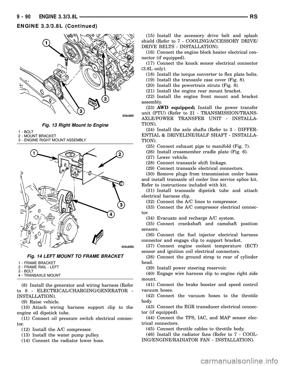
(8) Install the generator and wiring harness (Refer
to 8 - ELECTRICAL/CHARGING/GENERATOR -
INSTALLATION).
(9) Raise vehicle.
(10) Attach wiring harness support clip to the
engine oil dipstick tube.
(11) Connect oil pressure switch electrical connec-
tor.
(12) Install the A/C compressor.
(13) Install the water pump pulley.
(14) Connect the radiator lower hose.(15) Install the accessory drive belt and splash
shield (Refer to 7 - COOLING/ACCESSORY DRIVE/
DRIVE BELTS - INSTALLATION).
(16) Connect the engine block heater electrical con-
nector (if equipped).
(17) Connect the knock sensor electrical connector
(3.8L only).
(18) Install the torque converter to flex plate bolts.
(19) Install the transaxle case cover (Fig. 8).
(20) Install the powertrain struts (Fig. 8).
(21) Install the engine rear mount bracket.
(22) Install the engine front mount and bracket
assembly.
(23)AWD equipped;Install the power transfer
unit (PTU) (Refer to 21 - TRANSMISSION/TRANS-
AXLE/POWER TRANSFER UNIT - INSTALLA-
TION).
(24) Install the axle shafts (Refer to 3 - DIFFER-
ENTIAL & DRIVELINE/HALF SHAFT - INSTALLA-
TION).
(25) Connect exhaust pipe to manifold (Fig. 7).
(26) Install crossmember cradle plate (Fig. 6).
(27) Lower vehicle.
(28) Connect transaxle shift linkage.
(29) Connect transaxle electrical connectors.
(30) Remove plugs from transmission cooler hoses
and install transaxle oil cooler line service splice kit.
Refer to instructions included with kit.
(31) Install transaxle dipstick tube and attach
electrical harness clip.
(32) Connect the A/C lines to compressor.
(33) Connect the A/C compressor electrical connec-
tor.
(34) Evacuate and recharge A/C system.
(35) Connect crankshaft and camshaft position
sensors.
(36) Connect the fuel injector electrical harness
connector and engage clip to support bracket.
(37) Connect engine coolant temperature (ECT)
sensor and ignition coil electrical connectors.
(38) Connect the ground strap to rear of cylinder
head.
(39) Install power steering reservoir.
(40) Engage wire harness clip to engine right side
mount.
(41) Connect the brake booster and speed control
vacuum hoses.
(42) Connect the vacuum hoses to the throttle
body.
(43) Connect the EGR transducer electrical connec-
tor (if equipped).
(44) Connect the TPS, IAC, and MAP sensor elec-
trical connectors.
(45) Connect throttle cables to throttle body.
(46) Install the radiator fans (Refer to 7 - COOL-
ING/ENGINE/RADIATOR FAN - INSTALLATION).
Fig. 13 Right Mount to Engine
1 - BOLT
2 - MOUNT BRACKET
3 - ENGINE RIGHT MOUNT ASSEMBLY
Fig. 14 LEFT MOUNT TO FRAME BRACKET
1 - FRAME BRACKET
2 - FRAME RAIL - LEFT
3 - BOLT
4 - TRANSAXLE MOUNT
9 - 90 ENGINE 3.3/3.8LRS
ENGINE 3.3/3.8L (Continued)
Page 1452 of 2585
(17) Remove the water pump for cover removal
clearance. (Refer to 7 - COOLING/ENGINE/WATER
PUMP - REMOVAL)
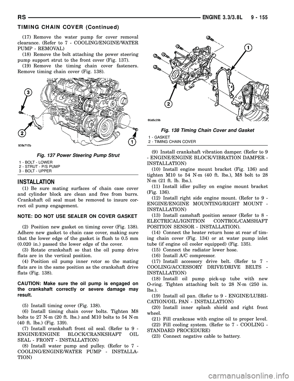
(18) Remove the bolt attaching the power steering
pump support strut to the front cover (Fig. 137).
(19) Remove the timing chain cover fasteners.
Remove timing chain cover (Fig. 138).
INSTALLATION
(1) Be sure mating surfaces of chain case cover
and cylinder block are clean and free from burrs.
Crankshaft oil seal must be removed to insure cor-
rect oil pump engagement.
NOTE: DO NOT USE SEALER ON COVER GASKET
(2) Position new gasket on timing cover (Fig. 138).
Adhere new gasket to chain case cover, making sure
that the lower edge of the gasket is flush to 0.5 mm
(0.020 in.) passed the lower edge of the cover.
(3) Rotate crankshaft so that the oil pump drive
flats are in the vertical position.
(4) Position oil pump inner rotor so the mating
flats are in the same position as the crankshaft drive
flats (Fig. 138).
CAUTION: Make sure the oil pump is engaged on
the crankshaft correctly or severe damage may
result.
(5) Install timing cover (Fig. 138).
(6) Install timing chain cover bolts. Tighten M8
bolts to 27 N´m (20 ft. lbs.) and M10 bolts to 54 N´m
(40 ft. lbs.) (Fig. 139).
(7) Install crankshaft front oil seal. (Refer to 9 -
ENGINE/ENGINE BLOCK/CRANKSHAFT OIL
SEAL - FRONT - INSTALLATION)
(8) Install water pump and pulley. (Refer to 7 -
COOLING/ENGINE/WATER PUMP - INSTALLA-
TION)(9) Install crankshaft vibration damper. (Refer to 9
- ENGINE/ENGINE BLOCK/VIBRATION DAMPER -
INSTALLATION)
(10) Install engine mount bracket (Fig. 136) and
tighten M10 to 54 N´m (40 ft. lbs.), M8 bolt to 28
N´m (21 ft. lb. lbs.).
(11) Install idler pulley on engine mount bracket
(Fig. 136).
(12) Install right side engine mount. (Refer to 9 -
ENGINE/ENGINE MOUNTING/RIGHT MOUNT -
INSTALLATION)
(13) Install camshaft position sensor (Refer to 8 -
ELECTRICAL/IGNITION CONTROL/CAMSHAFT
POSITION SENSOR - INSTALLATION).
(14) Connect the heater return hose at rear of tim-
ing chain cover (Fig. 134) or at water pump inlet
tube (if engine oil cooler equipped) (Fig. 135).
(15) Connect the radiator lower hose.
(16) Install A/C compressor.
(17) Install accessory drive belt. (Refer to 7 -
COOLING/ACCESSORY DRIVE/DRIVE BELTS -
INSTALLATION)
(18) Install oil pump pick-up tube with new
O-ring. Tighten attaching bolt to 28 N´m (250 in.
lbs.).
(19) Install oil pan. (Refer to 9 - ENGINE/LUBRI-
CATION/OIL PAN - INSTALLATION)
(20) Install inner splash shield and right front
wheel.
(21) Fill crankcase with engine oil to proper level.
(22) Fill cooling system. (Refer to 7 - COOLING -
STANDARD PROCEDURE)
(23) Connect negative cable to battery.
Fig. 137 Power Steering Pump Strut
1 - BOLT - LOWER
2 - STRUT - P/S PUMP
3 - BOLT - UPPER
Fig. 138 Timing Chain Cover and Gasket
1 - GASKET
2 - TIMING CHAIN COVER
RSENGINE 3.3/3.8L9 - 155
TIMING CHAIN COVER (Continued)
Page 1521 of 2585
QUICK CONNECT FITTING
STANDARD PROCEDURE - QUICK-CONNECT
FITTINGS
REMOVAL
When disconnecting a quick-connect fitting, the
retainer will remain on the fuel tube nipple.
WARNING: RELEASE FUEL SYSTEM PRESSURE
BEFORE DISCONNECTING A QUICK-CONNECT FIT-
TINGS. REFER TO THE FUEL PRESSURE RELEASE
PROCEDURE. THIS MAY RESULT IN PERSONAL
INJURY OR DEATH.
(1) Perform Fuel Pressure Release Procedure.
Refer to the Fuel Pressure Release Procedure in this
section.
(2) Disconnect negative cable from battery or aux-
iliary jumper terminal.
(3) Squeeze retainer tabs together and pull fuel
tube/quick-connect fitting assembly off of fuel tube
nipple. The retainer will remain on fuel tube.
INSTALLATION
CAUTION: Make sure that the o-ring in installed in
fitting. Never install a quick-connect fitting without
the retainer being either on the fuel tube or already
in the quick-connect fitting. In either case, ensure
the retainer locks securely into the quick-connect
fitting by firmly push-pulling-push on fuel tube and
fitting to ensure it is secured.
(1) Using a clean lint free cloth, clean the fuel tube
nipple and retainer.
(2) Prior to connecting the fitting to the fuel tube,
coat the fuel tube nipple with clean engine oil.
(3) Push the quick-connect fitting over the fuel
tube until theretainer seats and a click is heard.
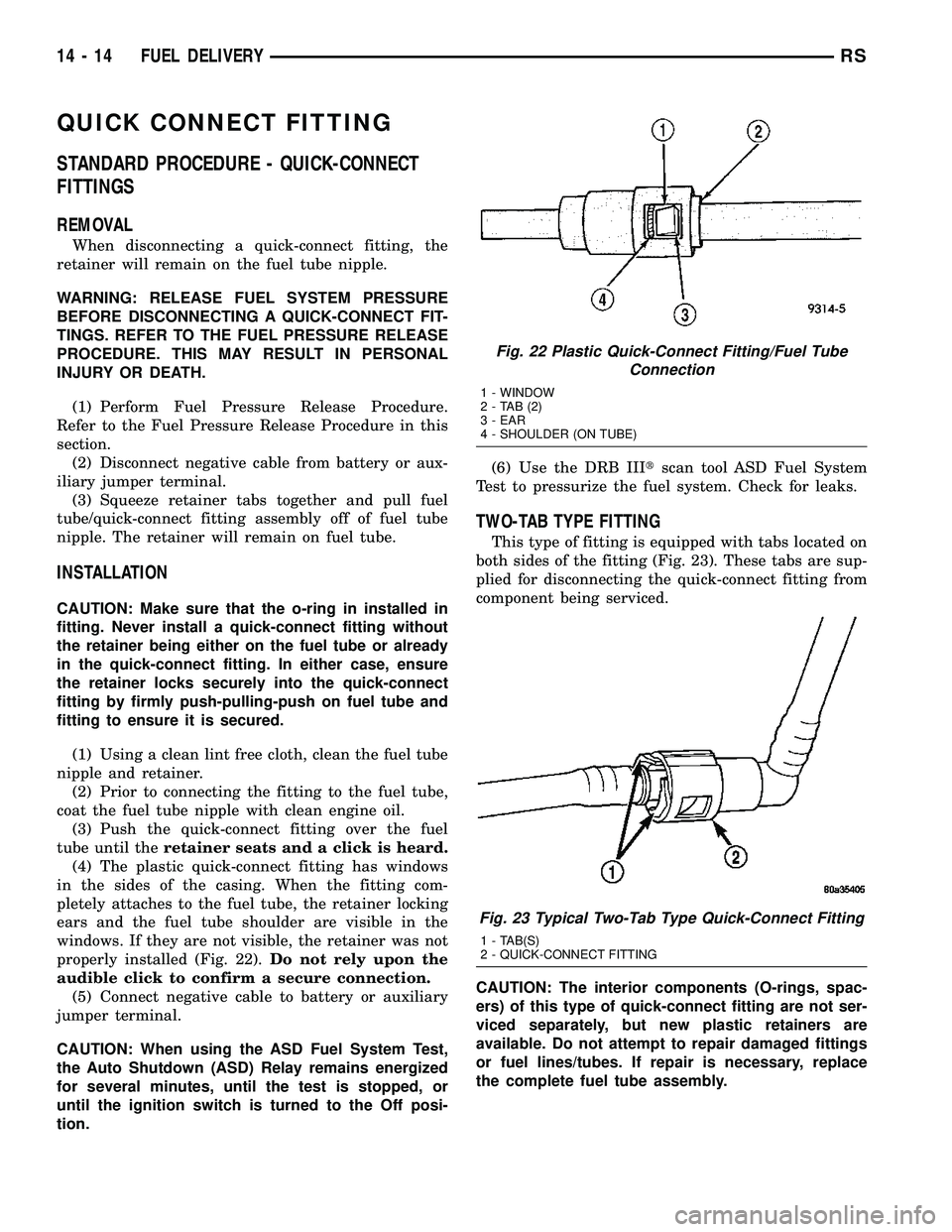
(4) The plastic quick-connect fitting has windows
in the sides of the casing. When the fitting com-
pletely attaches to the fuel tube, the retainer locking
ears and the fuel tube shoulder are visible in the
windows. If they are not visible, the retainer was not
properly installed (Fig. 22).Do not rely upon the
audible click to confirm a secure connection.
(5) Connect negative cable to battery or auxiliary
jumper terminal.
CAUTION: When using the ASD Fuel System Test,
the Auto Shutdown (ASD) Relay remains energized
for several minutes, until the test is stopped, or
until the ignition switch is turned to the Off posi-
tion.(6) Use the DRB IIItscan tool ASD Fuel System
Test to pressurize the fuel system. Check for leaks.
TWO-TAB TYPE FITTING
This type of fitting is equipped with tabs located on
both sides of the fitting (Fig. 23). These tabs are sup-
plied for disconnecting the quick-connect fitting from
component being serviced.
CAUTION: The interior components (O-rings, spac-
ers) of this type of quick-connect fitting are not ser-
viced separately, but new plastic retainers are
available. Do not attempt to repair damaged fittings
or fuel lines/tubes. If repair is necessary, replace
the complete fuel tube assembly.
Fig. 22 Plastic Quick-Connect Fitting/Fuel Tube
Connection
1 - WINDOW
2-TAB(2)
3 - EAR
4 - SHOULDER (ON TUBE)
Fig. 23 Typical Two-Tab Type Quick-Connect Fitting
1 - TAB(S)
2 - QUICK-CONNECT FITTING
14 - 14 FUEL DELIVERYRS
Page 1535 of 2585
(3) Disconnect injector wiring connector from injec-
tor.
(4) Position fuel rail assembly so that the fuel
injectors are easily accessible (Fig. 13).
(5) Rotate injector and pull injector out of fuel rail.
The clip will stay on the injector.
(6) Check injector O-ring for damage. If O-ring is
damaged, it must be replaced. If injector is reused, a
protective cap must be installed on the injector tip to
prevent damage. Replace the injector clip if it is dam-
aged.
(7) Repeat for remaining injectors.
INSTALLATION
INSTALLATION - 2.4L
The fuel rail must be removed first. Refer to Fuel
Injector Rail Removal in this section.
(1) Before installing an injector the rubber O-ring
must be lubricated with a drop of clean engine oil to
aid in installation.
(2) Install injector clip by sliding open end into the
top slot of the injector. The edge of the receiver cup
will slide into the side slots of clip.
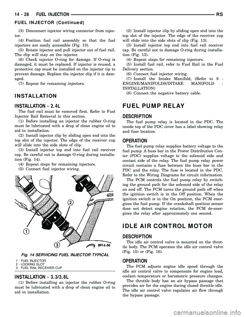
(3) Install injector top end into fuel rail receiver
cap. Be careful not to damage O-ring during installa-
tion (Fig. 14).
(4) Repeat steps for remaining injectors.
(5) Connect fuel injector wiring.
INSTALLATION - 3.3/3.8L
(1) Before installing an injector the rubber O-ring
must be lubricated with a drop of clean engine oil to
aid in installation.(2) Install injector clip by sliding open end into the
top slot of the injector. The edge of the receiver cup
will slide into the side slots of clip (Fig. 13).
(3) Install injector top end into fuel rail receiver
cap. Be careful not to damage O-ring during installa-
tion (Fig. 13).
(4) Repeat steps for remaining injectors.
(5) Install fuel rail, refer to Fuel Rail in the Fuel
Delivery section.
(6) Connect fuel injector wiring.
(7) Install the Intake Manifold, (Refer to 9 -
ENGINE/MANIFOLDS/INTAKE MANIFOLD -
INSTALLATION)
(8) Connect the negative battery cable.
FUEL PUMP RELAY
DESCRIPTION
The fuel pump relay is located in the PDC. The
inside top of the PDC cover has a label showing relay
and fuse location.
OPERATION
The fuel pump relay supplies battery voltage to the
fuel pump. A buss bar in the Power Distribution Cen-
ter (PDC) supplies voltage to the solenoid side and
contact side of the relay. The fuel pump relay power
circuit contains a fuse between the buss bar in the
PDC and the relay. The fuse is located in the PDC.
Refer to the Wiring Diagrams for circuit information.
The PCM controls the fuel pump relay by switch-
ing the ground path for the solenoid side of the relay
on and off. The PCM turns the ground path off when
the ignition switch is in the Off position. When the
ignition switch is in the On position, the PCM ener-
gizes the fuel pump. If the crankshaft position sensor
does not detect engine rotation, the PCM de-ener-
gizes the relay after approximately one second.
IDLE AIR CONTROL MOTOR
DESCRIPTION
The idle air control valve is mounted on the throt-
tle body. The PCM operates the idle air control valve
(Fig. 15) or (Fig. 16).
OPERATION
The PCM adjusts engine idle speed through the
idle air control valve to compensate for engine load,
coolant temperature or barometric pressure changes.
The throttle body has an air bypass passage that
provides air for the engine during closed throttle idle.
The idle air control valve regulates air flow through
the bypass passage.
Fig. 14 SERVICING FUEL INJECTOR TYPICAL
1 - FUEL INJECTOR
2 - LOCKING SLOT
3 - FUEL RAIL RECEIVER CUP
14 - 28 FUEL INJECTIONRS
FUEL INJECTOR (Continued)