Page 90 of 130

PERIODIC MAINTENANCE AND MINOR REPAIR
6-33
6
EAU03608
To adjust the drive chain slack
1. Loosen the axle nut and the lock-
nut on each side of the swingarm.
2. To tighten the drive chain, turn the
adjusting bolt on each side of the
swingarm in direction
a. To loos-
en the drive chain, turn the adjust-
ing bolt on each side of the
swingarm in direction
b, and then
push the rear wheel forward.
NOTE:_ Using the alignment marks on each
side of the swingarm, make sure that
both chain pullers are in the same posi-
tion for proper wheel alignment. _
EC000096
CAUTION:_ Improper drive chain slack will over-
load the engine as well as other vital
parts of the motorcycle and can lead
to chain slippage or breakage. To
prevent this from occurring, keep
the drive chain slack within the
specified limits. _3. Tighten the locknuts, and then
tighten the axle nut to the specified
torque.
EAU03006
Lubricating the drive chain The drive chain must be cleaned and
lubricated at the intervals specified in
the periodic maintenance and lubrica-
tion chart, otherwise it will quickly wear
out, especially when riding in dusty or
wet areas. Service the drive chain as
follows.
EC000097
CAUTION:@ The drive chain must be lubricated
after washing the motorcycle or
riding in the rain. @1. Clean the drive chain with kero-
sene and a small soft brush.
ECA00053
CAUTION:@ To prevent damaging the O-rings,
do not clean the drive chain with
steam cleaners, high-pressure
washers or inappropriate solvents. @2. Wipe the drive chain dry.
3. Thoroughly lubricate the drive
chain with a special O-ring chain
lubricant.
1. Axle nut
2. Drive chain slack adjusting bolt
3. Locknut
4. Alignment marks
Tightening torque:
Axle nut:
110 Nm (11.0 m·kgf)
U5SLE0.book Page 33 Wednesday, September 11, 2002 11:46 AM
Page 94 of 130

PERIODIC MAINTENANCE AND MINOR REPAIR
6-37
6
EAU02939
Checking the front fork The condition and operation of the front
fork must be checked as follows at the
intervals specified in the periodic main-
tenance and lubrication chart.
To check the condition
EW000115
WARNING
@ Securely support the motorcycle so
that there is no danger of it falling
over. @Check the inner tubes for scratches,
damage and excessive oil leakage.To check the operation
1. Place the motorcycle on a level
surface and hold it in an upright
position.
2. While applying the front brake,
push down hard on the handle-
bars several times to check if the
front fork compresses and re-
bounds smoothly.
EC000098
CAUTION:@ If any damage is found or the front
fork does not operate smoothly,
have a Yamaha dealer check or re-
pair it. @
EAU00794
Checking the steering Worn or loose steering bearings may
cause danger. Therefore, the operation
of the steering must be checked as fol-
lows at the intervals specified in the pe-
riodic maintenance and lubrication
chart.
1. Place a stand under the engine to
raise the front wheel off the
ground.
EW000115
WARNING
@ Securely support the motorcycle so
that there is no danger of it falling
over. @
U5SLE0.book Page 37 Wednesday, September 11, 2002 11:46 AM
Page 95 of 130

PERIODIC MAINTENANCE AND MINOR REPAIR
6-38
6 2. Hold the lower ends of the front
fork legs and try to move them for-
ward and backward. If any free
play can be felt, have a Yamaha
dealer check or repair the
steering.
EAU01144
Checking the wheel bearings The front and rear wheel bearings must
be checked at the intervals specified in
the periodic maintenance and lubrica-
tion chart. If there is play in the wheel
hub or if the wheel does not turn
smoothly, have a Yamaha dealer
check the wheel bearings.
EAU01291
Battery This motorcycle is equipped with a
sealed-type (MF) battery, which does
not require any maintenance. There is
no need to check the electrolyte or to
add distilled water.
To charge the battery
Have a Yamaha dealer charge the bat-
tery as soon as possible if it seems to
have discharged. Keep in mind that the
battery tends to discharge more quickly
if the motorcycle is equipped with op-
tional electrical accessories.
U5SLE0.book Page 38 Wednesday, September 11, 2002 11:46 AM
Page 102 of 130

PERIODIC MAINTENANCE AND MINOR REPAIR
6-45
6
EAU04574
Replacing the license plate
light bulb 1. Remove the license plate light unit
by removing the screws.2. Remove the socket (together with
the bulb) by pulling it out.
3. Remove the defective bulb by pull-
ing it out.
4. Insert a new bulb into the socket.
5. Install the socket (together with
the bulb) by pushing it in.
6. Install the license plate light unit by
installing the screws.
EAU01579
Supporting the motorcycle Since this model is not equipped with a
centerstand, follow these precautions
when removing the front and rear
wheel or performing other mainte-
nance requiring the motorcycle to
stand upright. Check that the motor-
cycle is in a stable and level position
before starting any maintenance. A
strong wooden box can be placed un-
der the engine for added stability.
To service the front wheel
1. Stabilize the rear of the motorcycle
by using a motorcycle stand or, if
an additional motorcycle stand is
not available, by placing a jack un-
der the frame in front of the rear
wheel.
2. Raise the front wheel off the
ground by using a motorcycle
stand.
1. Screw (× 2)
1. License plate light bulb
2. License plate light unit
U5SLE0.book Page 45 Wednesday, September 11, 2002 11:46 AM
Page 103 of 130
PERIODIC MAINTENANCE AND MINOR REPAIR
6-46
6 To service the rear wheel
Raise the rear wheel off the ground by
using a motorcycle stand or, if a motor-
cycle stand is not available, by placing
a jack either under each side of the
frame in front of the rear wheel or under
each side of the swingarm.
EAU04956
Front wheel To remove the front wheel
EW000122
WARNING
_ �
It is advisable to have a Yamaha
dealer service the wheel.
�
Securely support the motor-
cycle so that there is no danger
of it falling over.
_1. Loosen the axle bolt, the wheel
axle pinch bolts, and then the
brake caliper bolts.2. Lift the front wheel off the ground
according to the procedure on
page 6-45.
3. Remove the brake hose holder on
each side by removing the bolt.
4. Remove the brake caliper on each
side by removing the bolts.1. Front wheel axle pinch bolt (× 4)
1. Brake hose holder
2. Brake caliper
3. Axle bolt
4. Bolt (× 3)
U5SLE0.book Page 46 Wednesday, September 11, 2002 11:46 AM
Page 104 of 130

PERIODIC MAINTENANCE AND MINOR REPAIR
6-47
65. Remove the axle bolt, pull the
wheel axle out, and then remove
the wheel.
ECA00046
CAUTION:_ Do not apply the brake after the
brake calipers have been removed,
otherwise the brake pads will be
forced shut. _
EAU05021
To install the front wheel
1. Lift the wheel up between the fork
legs.
2. Insert the wheel axle.
3. Lower the front wheel so that it is
on the ground.
4. Install the brake calipers by install-
ing the bolts, and then tightening
them to the specified torque.NOTE:_ Make sure that there is enough space
between the brake pads before install-
ing the brake calipers onto the brake
discs. _5. Install the brake hose holders by
installing the bolts.
6. Secure the wheel axle by installing
the axle bolt, and then tightening
the wheel axle to the specified
torque.
NOTE:_ While tightening the wheel axle, hold
the axle bolt to keep it from turning. _
1. Wheel axle
Tightening torque:
Brake caliper bolt:
40 Nm (4.0 m·kgf)
Tightening torque:
Wheel axle:
91 Nm (9.1 m·kgf)
E_5sl_Periodic.fm Page 47 Thursday, October 17, 2002 1:13 PM
Page 105 of 130
PERIODIC MAINTENANCE AND MINOR REPAIR
6-48
6 7. Tighten wheel axle pinch bolt B,
and then tighten pinch bolt A to the
specified torque.
8. Retighten pinch bolt B to the spec-
ified torque.
9. Tap the outer side of the left fork
leg with a rubber mallet to align it
with the end of the wheel axle.10. Tighten wheel axle pinch bolt D,
and then tighten pinch bolt C to the
specified torque.
11. Retighten pinch bolt D to the spec-
ified torque.
12. While applying the front brake,
push down hard on the handlebar
several times to check for proper
fork operation.
1. Front wheel axle pinch bolt A
2. Front wheel axle pinch bolt B
3. Front wheel axle pinch bolt C
4. Front wheel axle pinch bolt D
Tightening torque:
Wheel axle pinch bolt:
18 Nm (1.8 m·kgf)
Tightening torque:
Wheel axle pinch bolt:
18 Nm (1.8 m·kgf)
E_5sl_Periodic.fm Page 48 Thursday, October 17, 2002 1:13 PM
Page 106 of 130
PERIODIC MAINTENANCE AND MINOR REPAIR
6-49
6
EAU04947
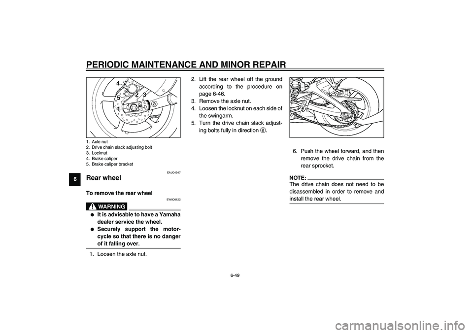
Rear wheel To remove the rear wheel
EW000122
WARNING
_ �
It is advisable to have a Yamaha
dealer service the wheel.
�
Securely support the motor-
cycle so that there is no danger
of it falling over.
_1. Loosen the axle nut.2. Lift the rear wheel off the ground
according to the procedure on
page 6-46.
3. Remove the axle nut.
4. Loosen the locknut on each side of
the swingarm.
5. Turn the drive chain slack adjust-
ing bolts fully in direction
a.
6. Push the wheel forward, and then
remove the drive chain from the
rear sprocket.
NOTE:_ The drive chain does not need to be
disassembled in order to remove and
install the rear wheel. _
1. Axle nut
2. Drive chain slack adjusting bolt
3. Locknut
4. Brake caliper
5. Brake caliper bracketU5SLE0.book Page 49 Wednesday, September 11, 2002 11:46 AM