Page 278 of 754
3 - 49
INSP
ADJ
IGNITION TIMING CHECK
IGNITION TIMING CHECK
1. Remove:
�Timing plug 1
1
2. Attach:
�Timing light
�Inductive tachometer
To the ignition coil lead (orange lead
1).
3. Check:
�Ignition timing
Timing light:
YM-33277-A/90890-03141
Inductive tachometer:
YU-8036-B
Engine tachometer:
90890-03113
Checking steps:
�Start the engine and let it warm up. Let the
engine run at the specified speed.
�Adjust the engine idling speed.
Refer to “IDLE SPEED ADJUSTMENT”
section.
�Visually check the stationary pointer a is
within the firing range b on the rotor.
Incorrect firing range → Check rotor and
pickup assembly.
1
4. Install:
�Timing plug
Page 298 of 754

3 - 57
INSP
ADJ
REPLACING THE HEADLIGHT BULBS
3. Replace:
�Blown fuse
WARNING
Never use a fuse with an amperage rating
other than that specified. Improvising or
using a fuse with the wrong amperage rat-
ing may cause extensive damage to the
electrical system, cause the starting and
ignition systems to malfunction and could
possibly cause a fire.
4. Install:
�Fuse cover
�Seat Replacement steps:
�Set the main switch to “OFF”.
�Install a new fuse of the correct amperage.
�Set on the switches to verify if the electri-
cal circuit is operational.
�If the fuse immediately blows again, check
the electrical circuit.
ItemsAmperage
ratingQ’ty
Main fuse 10 A 1
REPLACING THE HEADLIGHT BULBS
1. Remove:
�Headlight
Refer to “SEAT, FUEL TANK AND
SIDE COVERS” section in the CHAP-
TER 4.
2. Remove:
�Headlight bulb holder cover 1
3. Detach:
�Headlight bulb holder 1
4. Remove:
�Headlight bulb 2
WARNING
Since the headlight bulb gets extremely
hot, keep flammable products and your
hands away from the bulb unit it has cooled
down.
Page 466 of 754
4 - 83
ENGENGINE REMOVAL
EC4M0000
ENGINE REMOVAL
Extent of removal Order Part name Q’ty Remarks
ENGINE REMOVAL
Preparation for removal Hold the machine by placing the
suitable stand under the frame.
WARNING
Support the machine securely so there is no
danger of it falling over.
Drain the engine oil Refer to “ENGINE OIL REPLACEMENT”
section in the CHAPTER 3.
Seat and fuel tank Refer to “SEAT, FUEL TANK AND SIDE
COVERS” section.
Carburetor Refer to “CARBURETOR” section.
Exhaust pipe and silencer Refer to “EXHAUST PIPE AND
SILENCER” section.
Clutch cable and guide Disconnect at the engine side.
Radiator Refer to “RADIATOR” section.
Shift pedal Refer to “AC MAGNETO AND
STARTER CLUTCH” section.
Cylinder head breather hose and
oil tank breather hoseRefer to “CAMSHAFTS” section.
Ignition coil
Disconnect the AC magneto lead.
Page 642 of 754

6 - 1
–+ELEC
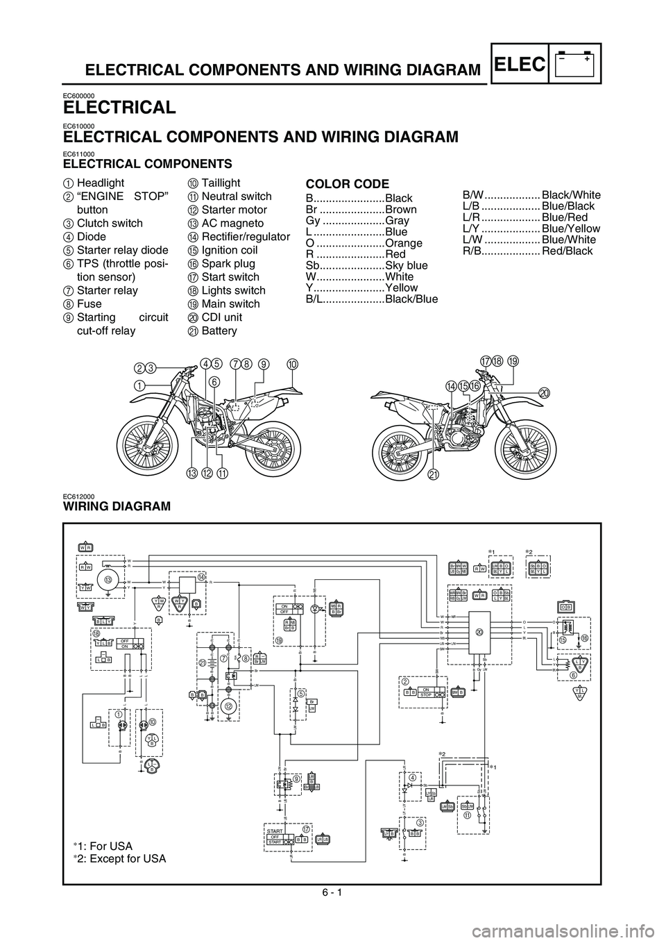
ELECTRICAL COMPONENTS AND WIRING DIAGRAM
EC600000
ELECTRICAL
EC610000
ELECTRICAL COMPONENTS AND WIRING DIAGRAM
EC611000
ELECTRICAL COMPONENTS
1
Headlight
2
“ENGINE STOP”
button
3
Clutch switch
4
Diode
5
Starter relay diode
6
TPS (throttle posi-
tion sensor)
7
Starter relay
8
Fuse
9
Starting circuit
cut-off relay
0
Taillight
A
Neutral switch
B
Starter motor
C
AC magneto
D
Rectifier/regulator
E
Ignition coil
F
Spark plug
G
Start switch
H
Lights switch
I
Main switch
J
CDI unit
K
Battery
COLOR CODE
B.......................Black
Br .....................Brown
Gy ....................Gray
L .......................Blue
O ......................Orange
R ......................Red
Sb.....................Sky blue
W......................White
Y.......................Yellow
B/L....................Black/Blue
EC612000
WIRING DIAGRAM
1 2345
678
90
A B
CDEFGH
I
J
K
WR
WR
R
BR/BBr
R
BR/BBr
RW
L/RL/BBB
SbL/W
WY
YW
L/YBBB
WY
RYW
R
LY
B
YLB/L
B
B
ON
OFF
10A
BB
OFF
ON
OFF
STARTSTART
R-BrL/W
BLY
YLB-LB
B
BrL/W
BrL/W
L/B-LB
YL
B
L-B
L/WSb
B/WBBB
W/RB/W
R/BGyBrL/W
ON
STOP
OB
LYSbB/L
W RBrB/W
L/BGyWR/B
B O
L/YSbL/R
R W
Y W
Y W
Y B
B
L
L L
L B
B
B
RRR/B
B Br B
B B B B
L/W
R
R
R R B
R
BrBr
L/W L/W
Br B
L/B
L/B
L/R
Br
R/B
L/B L/W
B/W
W W/RW
RO
L
Y
B/L
O
B
L
Y
B/LSbL/WB/W
B
L/R L/Y L/Y
B
SbSbL/W
BGy
SbBB/LYO
L
∗2
O B
L YL/W
B/L
∗1
C
HD
BI
5
9
G3 4
A 2J
EF
6 7
K8
1
0
∗
2
∗1
∗2: Except for USA
∗1: For USA
B/W .................. Black/White
L/B ................... Blue/Black
L/R ................... Blue/Red
L/Y ................... Blue/Yellow
L/W .................. Blue/White
R/B................... Red/Black
Page 644 of 754

–+ELEC
6 - 2
MAP-CONTROLLED CDI UNIT
MAP-CONTROLLED CDI UNIT
A map-controlled, CDI ignition system is used in the WR450F.
The microcomputer in the CDI unit detects the engine speed and throttle position, thus determining
the optimum ignition timing through the entire operating range. In this way, quick throttle response
can be achieved according to various riding conditions.
CDI unit
Throttle position sensor
Pickup coil AC magneto rotorIgnition coil
�
Function of Component
Component Function
TPS
(throttle position sensor)Detects throttle valve opening and inputs it into the computer in the
CDI unit as a throttle opening signal.
Pickup coil Detects signal rotor revolutions and inputs them into the computer in
the CDI unit as engine revolution signals.
CDI unit The signals of the TPS and pickup coil sensor are analyzed by the
computer in the CDI unit, which then adjusts ignition timing for the
operation requirements.
�
Principal of 3-Dimensional Control
Conventionally, ignition timing was controlled only
by engine revolutions (2-dimensional control).
However, ignition timing needs advancement also
by engine load. Thus, accurate ignition timing can
be determined by adding throttle opening to deter-
mine ignition timing (3-dimensional control).
3-D Image Map of Ignition Timing
(different from actual characteristics)
Revolutions
Ignition timing
Throttle opening
Page 648 of 754

–+ELEC
6 - 3
IGNITION SYSTEM
EC620000
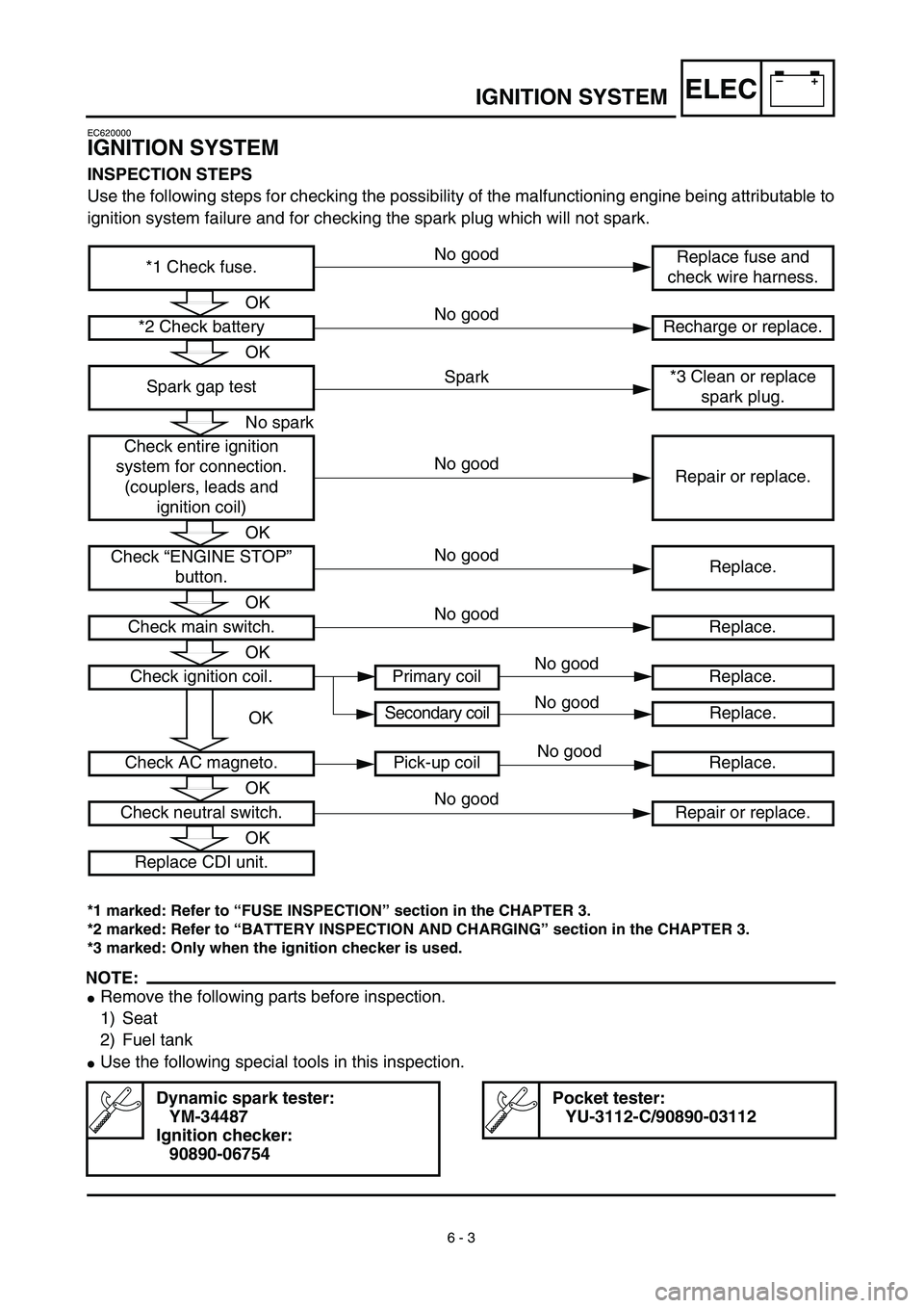
IGNITION SYSTEM
INSPECTION STEPS
Use the following steps for checking the possibility of the malfunctioning engine being attributable to
ignition system failure and for checking the spark plug which will not spark.
*1 marked: Refer to “FUSE INSPECTION” section in the CHAPTER 3.
*2 marked: Refer to “BATTERY INSPECTION AND CHARGING” section in the CHAPTER 3.
*3 marked: Only when the ignition checker is used.
NOTE:
�
Remove the following parts before inspection.
1) Seat
2) Fuel tank
�
Use the following special tools in this inspection.
Dynamic spark tester:
YM-34487
Ignition checker:
90890-06754
Pocket tester:
YU-3112-C/90890-03112
*1 Check fuse.Replace fuse and
check wire harness.
*2 Check battery Recharge or replace.
Spark gap test*3 Clean or replace
spark plug.
Check entire ignition
system for connection.
(couplers, leads and
ignition coil)Repair or replace.
Check “ENGINE STOP”
button.Replace.
Check main switch. Replace.
Check ignition coil. Primary coil Replace.
Secondary coil Replace.
Check AC magneto. Pick-up coil Replace.
Check neutral switch. Repair or replace.
Replace CDI unit.
OK
OK
No spark
OK
OK
OK
OK
OK
OK
Spark
No good
No good
No good
No good
No good
No good
No good
No good
No good
Page 652 of 754

6 - 4
–+ELEC
IGNITION SYSTEM
SPARK GAP TEST
1. Disconnect the ignition coil from spark
plug.
2. Remove the ignition coil cap.
3. Connect the dynamic spark tester
1
(ignition checker
2
) as shown.
�
Ignition coil
3
�
Spark plug
4
Å
For USA and CDN
ı
Except for USA and CDN
4. Kick the kickstarter.
5. Check the ignition spark gap.
6. Start engine, and increase spark gap until
misfire occurs. (for USA and CDN only)
Minimum spark gap:
6.0 mm (0.24 in)
Å
ı
COUPLERS, LEADS AND IGNITION COIL
CONNECTION INSPECTION
1. Check:
�
Couplers and leads connection
Rust/dust/looseness/short-circuit →
Repair or replace.
�Ignition coil and spark plug as they are
fitted
Push in the ignition coil until it closely
contacts the spark plug hole in the cyl-
inder head cover.
EC625001
“ENGINE STOP” BUTTON INSPECTION
1. Inspect:
�“ENGINE STOP” button conduct
No continuity while being pushed → Replace.
Continuity while being freed → Replace.
2. Inspect:
�Rubber part a
Tears/damage → Replace. Tester (+) lead → Black lead 1
Tester (–) lead → Black lead 2
B
1B
2Tester selector
position
PUSH IN
Ω × 1
FREE
a
Page 654 of 754
6 - 5
–+ELECIGNITION SYSTEM
MAIN SWITCH INSPECTION
1. Inspect:
�Main switch conduct
Continuous while the main switch is moved to
“OFF” → Replace.
Not continuous while the main switch is moved
to “ON” → Replace.
2. Inspect:
�Main switch indicator light
Use 12 V battery.
Indicator light does not come on → Replace.
3. Inspect:
�Rubber part a
Tears/damage → Replace. Tester (+) lead → Red lead 1
Tester (–) lead → Brown lead 2
R
1Br
2Tester selector
position
ON
Ω × 1
OFF
Battery (+) lead → Red/Black lead 1
Battery (–) lead → Black lead 2
a
EC626002
IGNITION COIL INSPECTION
1. Remove the ignition coil cap.
2. Inspect:
�Primary coil resistance
Out of specification → Replace.
Tester (+) lead → Orange lead 1
Tester (–) lead → Black lead 2
Primary coil
resistanceTester selector
position
0.08 ~ 0.10 Ω at
20 ˚C (68 ˚F)Ω × 1