Page 300 of 340
6 - 4
–+ELECIGNITION SYSTEM
“ENGINE STOP” SWITCH INSPECTION
1. Inspect:
�“ENGINE STOP” switch continuity
No continuous while being pushed → Replace.
Continuous while being free → Replace. Tester (+) lead → Black lead 1
Tester (–) lead → Black lead 2
B
1B
2Tester selec-
tor position
PUSH IN
Ω × 1
FREE
B B
1
2
EC626002
IGNITION COIL INSPECTION
1. Inspect:
�Primary coil resistance
Out of specification → Replace.
2. Inspect:
�Secondary coil resistance
Out of specification → Replace.
NOTE:
When inspecting the secondary coil resis-
tance, remove the spark plug cap.Tester (+) lead → Orange lead 1
Tester (–) lead → Black lead 2
Primary coil
resistanceTester selector
position
0.18 ~ 0.28 Ω at
20 ˚C (68 ˚F)Ω × 1
Tester (+) lead → Spark plug lead 1
Tester (–) lead → Orange lead 2
Secondary coil
resistanceTester selector
position
6.3 ~ 9.5 kΩ at
20 ˚C (68 ˚F)kΩ × 1
Page 302 of 340
6 - 5
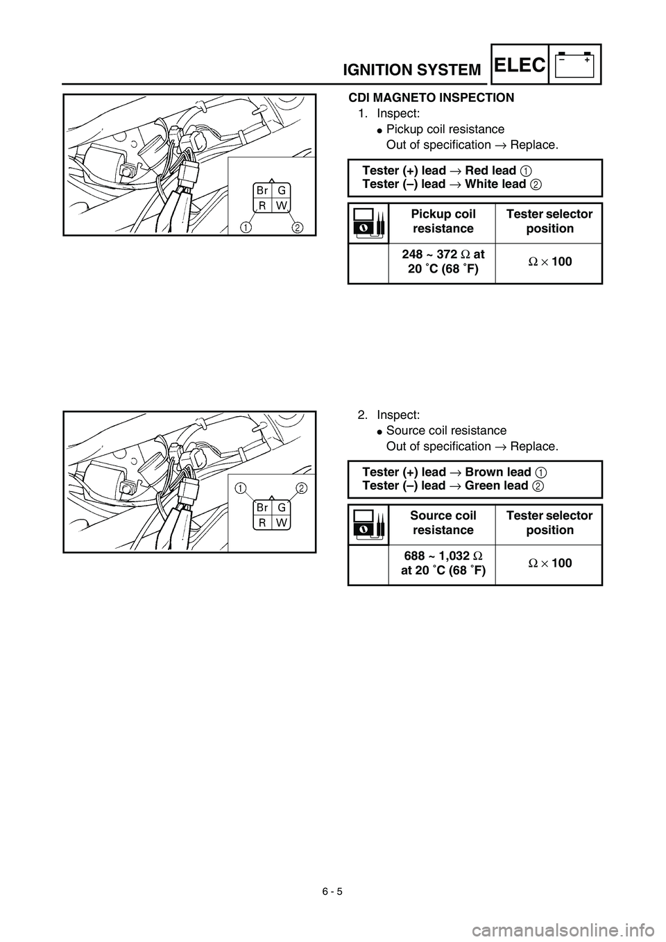
–+ELECIGNITION SYSTEM
CDI MAGNETO INSPECTION
1. Inspect:
�Pickup coil resistance
Out of specification → Replace.
Tester (+) lead → Red lead 1
Tester (–) lead → White lead 2
Pickup coil
resistanceTester selector
position
248 ~ 372 Ω at
20 ˚C (68 ˚F)Ω × 100
2. Inspect:
�Source coil resistance
Out of specification → Replace.
Tester (+) lead → Brown lead 1
Tester (–) lead → Green lead 2
Source coil
resistanceTester selector
position
688 ~ 1,032 Ω
at 20 ˚C (68 ˚F)Ω × 100
Page 316 of 340
6 - 11
–+ELEC
STARTER MOTOR
Extent of removal:1 Starter motor disassembly
Extent of removal Order Part name Q’ty Remarks
STARTER MOTOR REMOVAL
Preparation for removal Drain the engine oil Refer to “ENGINE OIL REPLACEMENT”
section in the CHAPTER 3.
1 Starter motor 1
STARTER MOTOR DISASSEM-
BLY
1Front bracket 1
2Ring 1
3Brush set 1
4Armature assembly 1
5Stator assembly 1
1
ELECTRIC STARTING SYSTEM
Page 318 of 340
6 - 12
–+ELEC
INSPECTION AND REPAIR
1. Inspect:
�Commutator
Dirt → Clean it with #600 grit sandpaper.
2. Measure:
�Commutator diameter a
Out of specification → Replace the
starter motor.
3. Measure:
�Mica undercut a
Out of specification → Scrape the mica
to the proper value (a hacksaw blade
can be ground to fit).
NOTE:
The mica insulation of the commutator must be
undercut to ensure proper operation of com-
mutator.
Commutator wear limit:
16.6 mm (0.65 in)
Mica undercut:
1.35 mm (0.05 in)
4. Measure:
�Armature assembly resistance (com-
mutator and insulation)
Out of specification → Replace the
starter motor.
Measurement steps:
�Measure the armature assembly resis-
tances with the pocket tester.
Pocket tester
YU-3112-C/90890-03112
Armature coil:
Commutator resistance 1
0.018 ~ 0.022 Ω at 20 ˚C (68 ˚F)
Insulation resistance 2
Above 1 MΩ at 20 ˚C (68 ˚F)
�If any resistance is out of specification,
replace the starter motor.
ELECTRIC STARTING SYSTEM
Page 320 of 340
6 - 13
–+ELEC
5. Measure:
�Brush length a
Out of specification → Replace.
Brush length wear limit:
3.5 mm (0.14 in)
6. Measure:
�Brush spring force
Fatigue/out of specification → Replace
as a set.
Brush spring force:
3.92 ~ 5.88 N
(400 ~ 600 g, 14.1 ~ 21.2 oz)
ASSEMBLY
1. Install:
�Brush holder
2. Install:
�Armature coil 1
3. Install:
�Ring 1
�Stator assembly 2
�Front bracket 3
NOTE:
�Apply molybdenum grease lightly on to the
bearings of the starter motor.
�Align the match mark on the yoke with the
match mark on the bracket.
ELECTRIC STARTING SYSTEM
Page 322 of 340
–+ELEC
6 - 14
CHARGING SYSTEM
EC680000
CHARGING SYSTEM
EC681001
INSPECTION STEPS
If the battery is not charged, use the following inspection steps.
*1 marked: Refer to “FUSE INSPECTION” section in the CHAPTER 3.
*2 marked: Refer to “CHECKING AND CHARGING THE BATTERY” section in the CHAPTER 3.
NOTE:
�Remove the following parts before inspection.
1) Seat
2) Rear fender
3) Fuel tank
�Use the following special tool in this inspection.
Pocket tester:
YU-3112-C/90890-03112Inductive tachometer:
YU-8036-B
Engine tachometer:
90890-03113
*1 Check fuse.Replace fuse and
check wire harness.
*2 Check battery. Recharge or replace.
Check each coupler and
wire connection.Repair or replace.
Check charging voltage.Charging system is
good.
Check CDI magneto. Lighting coil Replace.
Replace rectifier/regulator.
OK
OK
OK
No good
OK
No good
No good
No good
No good
OK
Page 326 of 340
6 - 15
–+ELECCHARGING SYSTEM
EC624000
COUPLERS AND LEADS CONNECTION
INSPECTION
1. Check:
�Couplers and leads connection
Rust/dust/looseness/short-circuit →
Repair or replace.
CHARGING VOLTAGE INSPECTION
1. Start the engine.
2. Inspect:
�Charging voltage
Out of specification → If no failure is
found in checking the source coil resis-
tance, replace the rectifier/regulator.
Tester (+) lead → Red lead 1
Tester (–) lead → Black lead 2
Charging
voltageTester selector
position
14.0 ~ 15.0 V at
5,000 r/minDCV-20
WB
R
Y/R
12
3. Inspect:
�Lighting coil resistance
Out of specification → Replace.
Tester (+) lead → White lead 1
Tester (–) lead → Black lead 2
Lighting coil
resistanceTester selector
position
0.64 ~ 0.96 Ω at
20 ˚C (68 ˚F)Ω × 1
WSb
YB
1
2
Page 328 of 340
–+ELEC
6 - 16
CARBURETOR HEATING SYSTEM
CARBURETOR HEATING SYSTEM
INSPECTION STEPS
Use the following steps for checking the possibility of the malfunctioning carburetor heating system.
NOTE:
�Remove the following parts before inspection.
1) Seat
2) Fuel tank
�Use the following special tools in this inspection.
Check entire carburetor
heating system for connec-
tion.Repair or replace.
Check thermo switch. Replace.
Check carburetor heater. Replace.
Check CDI magneto. Lighting coil Replace.
Replace rectifier/regulator.
Pocket tester:
YU-3112-C/90890-03112
OK
OK
OK
No good
No good
No good
No good
OK