Page 188 of 578
3 - 13
INSP
ADJ
VALVE CLEARANCE INSPECTION AND ADJUSTMENT
�Measure the valve clearance.
�If the clearance is incorrect, repeat above
steps until specified clearance is obtained.
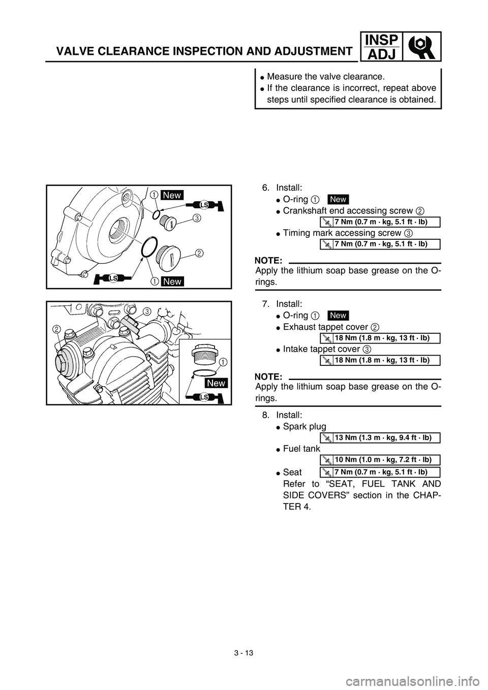
6. Install:
�O-ring 1
�Crankshaft end accessing screw 2
�Timing mark accessing screw 3
NOTE:
Apply the lithium soap base grease on the O-
rings.
New
T R..7 Nm (0.7 m · kg, 5.1 ft · lb)
T R..7 Nm (0.7 m · kg, 5.1 ft · lb)
7. Install:
�O-ring 1
�Exhaust tappet cover 2
�Intake tappet cover 3
NOTE:
Apply the lithium soap base grease on the O-
rings.
8. Install:
�Spark plug
�Fuel tank
�Seat
Refer to “SEAT, FUEL TANK AND
SIDE COVERS” section in the CHAP-
TER 4.
New
T R..18 Nm (1.8 m · kg, 13 ft · lb)
T R..18 Nm (1.8 m · kg, 13 ft · lb)
T R..13 Nm (1.3 m · kg, 9.4 ft · lb)
T R..10 Nm (1.0 m · kg, 7.2 ft · lb)
T R..7 Nm (0.7 m · kg, 5.1 ft · lb)
Page 220 of 578

3 - 29
INSP
ADJ
STEERING HEAD INSPECTION AND ADJUSTMENT
�Tighten the lower ring nut 6 using steer-
ing nut wrench 7 and turn the steering
right and left a few times.
Steering nut wrench:
YU-33975/90890-01403
T R..
Lower ring nut (initial tightening):
38 Nm (3.8 m • kg, 27 ft • lb)
�Loosen the lower ring nut one turn.
�Retighten the lower ring nut using the
steering nut wrench.
T R..
Ring nut (final tightening):
20 Nm (2.0 m • kg, 14 ft • lb)
�Check the steering stem by turning it lock
to lock. If there is any binding, remove the
steering stem assembly and inspect the
steering bearings.
�Install the rubber washer 8, upper ring
nut 9 and special washer 0.
NOTE:
�Tighten the upper ring nut until it contacts
the rubber washer.
�Insert the special washer pawls into the
slots. If the slots are not aligned, tighten
the upper ring nut for alignment.
�Install the upper bracket A, steering stem
nut B, cap C, handlebar D, upper han-
dlebar holder E, main switch F, starter
knob nut G and number plate H.
NOTE:
�The upper handlebar holder should be
installed with the punched mark a for-
ward.
�Insert the end of fuel breather hose I into
the hose clamp.
NOTE:
Set the torque wrench to the steering nut
wrench so that they form a right angle.
WARNING
Avoid over-tightening.
H
DF
B
C
I
A
Page 246 of 578
4 - 1
ENG
EC400000
ENGINE
EC4R0000
SEAT, FUEL TANK AND SIDE COVERS
Extent of removal:
1
Seat removal
2
Fuel tank removal
3
Side covers removal
4
Number plate removal
Extent of removal Order Part name Q’ty Remarks
Preparation for removal
SEAT, FUEL TANK AND SIDE
COVERS REMOVAL
Turn the fuel cock to “OFF”.
1 Seat 1
2 Air scoop (left and right) 2
3 Fuel hose 1 Remove on fuel tank side.
4 Fitting band 1
5 Bolt (fuel tank) 2
6 Fuel tank 1
7 Left side cover 1
8 Right side cover 1
9Number plate
1
13
4
2
3
SEAT, FUEL TANK AND SIDE COVERS
Page 248 of 578
4 - 2
ENG
MUFFLER
MUFFLER
Extent of removal:
1
Muffler removal
Extent of removal Order Part name Q’ty Remarks
MUFFLER REMOVAL
Preparation for removal Right side cover Refer to “SEAT, FUEL TANK AND SIDE
COVERS” section.
1 Bolt (spark arrester) 3
2 Spark arrester 1
3 Nut (muffler) 2
4 Bolt (muffler) 1
5Muffler
1
1
Page 250 of 578
4 - 3
ENG
CARBURETOR
CARBURETOR
Extent of removal:
1
Carburetor removal
Extent of removal Order Part name Q’ty Remarks
CARBURETOR REMOVAL
Preparation for removal Fuel tank
Refer to “SEAT, FUEL TANK AND SIDE
COVERS” section.
Number plate
1 Fuel hose 1
2 Over flow hose 1
3 Air vent hose 2
4 Starter plunger/starter knob 1
5 Carburetor top cover 1
6 Clamp (air cleaner joint) 1 Loosen the screw (air cleaner joint).
7 Clamp (carburetor joint) 1 Loosen the screws (carburetor joint).
8Carburetor
1
1
Page 254 of 578
4 - 5
ENG
CARBURETOR
HANDLING NOTE
At high altitudes, the atmospheric pressure is
lower. This can make the fuel mixture too rich,
leading to such problems as fouled.
Spark plugs and slow response at high engine
speeds. A special part, High Altitude Main Jet
1
#102.5 (620-1423A-71-A0) is available to
correct this.
EC463000
REMOVAL POINTS
Throttle valve
1. Remove:
�
Throttle valve
1
�
Spring (throttle valve)
2
�
Carburetor top cover
3
�
Throttle cable
4
NOTE:
While compressing the spring (throttle valve),
disconnect the throttle cable.
Pilot air screw
1. Remove:
�
Pilot air screw
1
NOTE:
To optimize the fuel flow at a smaller throttle
opening, each machine’s pilot air screw has
been individually set at the factory. Before
removing the pilot air screw, turn it in fully and
count the number of turns. Record this number
as the factory-set number of turns out.
Page 258 of 578

4 - 7
ENGCARBURETOR
EC464301
Throttle valve
1. Check:
�Free movement
Stick → Repair or replace.
NOTE:
Insert the throttle valve 1 into the carburetor
body, and check for free movement.
EC464401
Jet needle
1. Inspect:
�Jet needle 1
Bends/wear → Replace.
�Clip groove
Free play exists/wear → Replace.
�Clip position
Fuel level
1. Measure:
�Fuel level a
Out of specification → Adjust.
Standard clip position:
No. 2 Groove
Fuel level:
6.0 ~ 7.0 mm (0.24 ~ 0.28 in)
Below the float chamber mat-
ing surface
Measurement and adjustment steps:
�Connect the fuel level gauge 1 to the float
chamber.
Fuel level gauge:
YM-1312-A/90890-01312
�Hold the fuel level gauge vertically next to
the float chamber mating surface.
�Loosen the drain screw.
�Measure the fuel level with the fuel level
gauge.
NOTE:
Keep the carburetor and fuel level gauge
vertically when measuring the fuel level.
�If the fuel level is not within specification,
inspect the needle valve seat and needle valve.
�If either is worn, replace them both.
�If both are fine, adjust the fuel level by
bending the float tab b on the float.
�Recheck the fuel level.
Page 266 of 578
4 - 11
ENGCARBURETOR
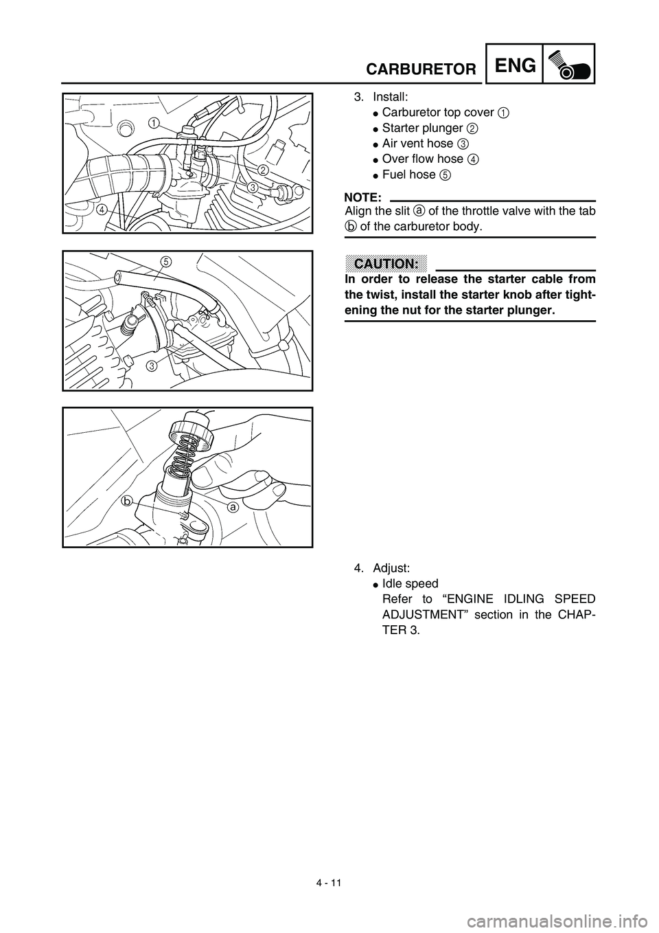
3. Install:
�Carburetor top cover 1
�Starter plunger 2
�Air vent hose 3
�Over flow hose 4
�Fuel hose 5
NOTE:
Align the slit a of the throttle valve with the tab
b of the carburetor body.
CAUTION:
In order to release the starter cable from
the twist, install the starter knob after tight-
ening the nut for the starter plunger.
4. Adjust:
�Idle speed
Refer to “ENGINE IDLING SPEED
ADJUSTMENT” section in the CHAP-
TER 3.