Page 432 of 510
 5 - 34
CHASFRONT FORK
HANDLING NOTE
NOTE:
The front fork requires careful attention. So it is
recommended that the front fork be main-
tained at the dealers.
CAUTION:
To prevent an accidental explosio")
5 - 34
CHASFRONT FORK
HANDLING NOTE
NOTE:
The front fork requires careful attention. So it is
recommended that the front fork be main-
tained at the dealers.
CAUTION:
To prevent an accidental explosion of air,
the following instructions should be
observed:
The front fork with a built-in piston rod has
a very sophisticated internal construction
and is particularly sensitive to foreign
material.
Use enough care not to allow any foreign
material to come in when the oil is replaced
or when the front fork is disassembled and
reassembled.
EC553000
REMOVAL POINTS
Cap bolt
1. Remove:
�Cap bolt 1
From the inner tube.
NOTE:
Before removing the front fork from the
machine, loosen the cap bolt.
Inner tube
1. Remove:
�Dust seal 1
�Stopper ring 2
Using slotted-head screwdriver.
CAUTION:
Take care not to scratch the inner tube.
2. Remove:
�Bolt (damper rod)
�Damper rod
�Inner tube
�Oil flow stopper
�Piston metal
NOTE:
Use the damper rod holder 1 and the T-han-
dle 2 to lock the damper rod.
Page 436 of 510
5 - 36
CHASFRONT FORK
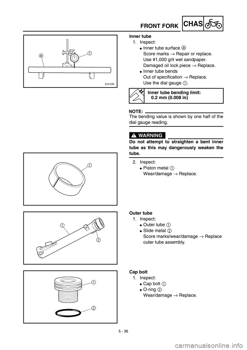
Inner tube
1. Inspect:
�Inner tube surface a
Score marks → Repair or replace.
Use #1,000 grit wet sandpaper.
Damaged oil lock piece → Replace.
�Inner tube bends
Out of specification → Replace.
Use the dial gauge 1.
NOTE:
The bending value is shown by one half of the
dial gauge reading.
WARNING
Do not attempt to straighten a bent inner
tube as this may dangerously weaken the
tube.
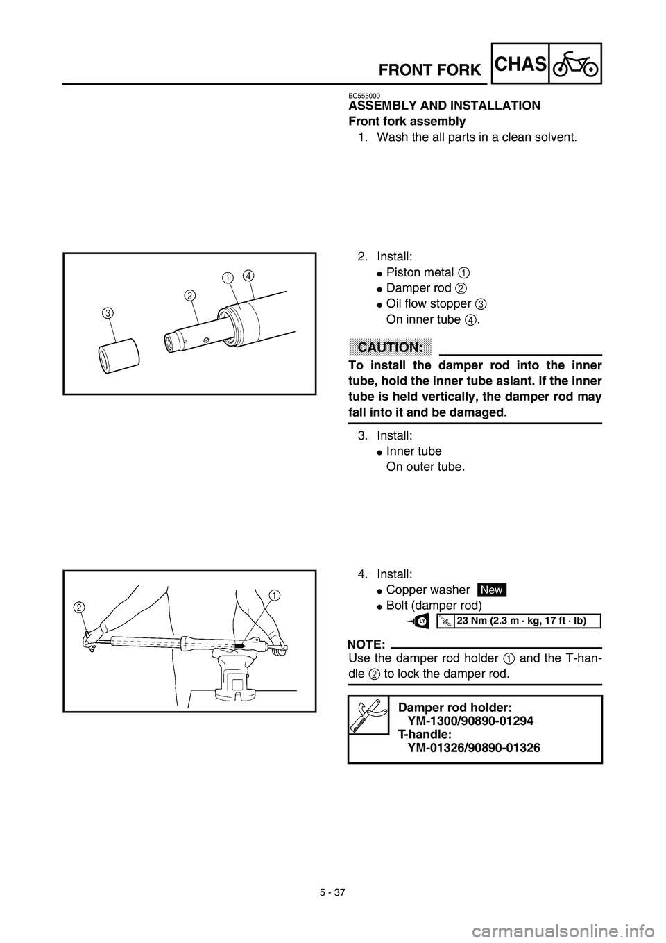
2. Inspect:
�Piston metal 1
Wear/damage → Replace.
Inner tube bending limit:
0.2 mm (0.008 in)
Outer tube
1. Inspect:
�Outer tube 1
�Slide metal 2
Score marks/wear/damage → Replace
outer tube assembly.
Cap bolt
1. Inspect:
�Cap bolt 1
�O-ring 2
Wear/damage → Replace.
Page 438 of 510
5 - 37
CHAS
EC555000
ASSEMBLY AND INSTALLATION
Front fork assembly
1. Wash the all parts in a clean solvent.
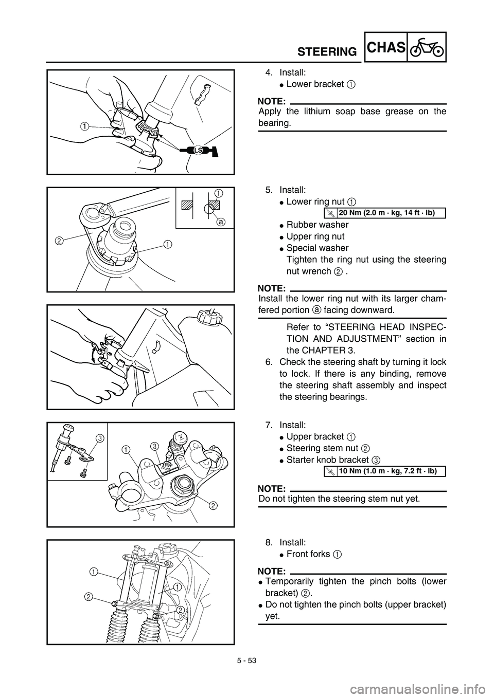
2. Install:
�Piston metal 1
�Damper rod 2
�Oil flow stopper 3
On inner tube 4.
CAUTION:
To install the damper rod into the inner
tube, hold the inner tube aslant. If the inner
tube is held vertically, the damper rod may
fall into it and be damaged.
3. Install:
�Inner tube
On outer tube.
4. Install:
�Copper washer
�Bolt (damper rod)
NOTE:
Use the damper rod holder 1 and the T-han-
dle 2 to lock the damper rod.
Damper rod holder:
YM-1300/90890-01294
T-handle:
YM-01326/90890-01326
New
T R..23 Nm (2.3 m · kg, 17 ft · lb)LT
FRONT FORK
Page 470 of 510
5 - 53
CHAS
4. Install:
�Lower bracket 1
NOTE:
Apply the lithium soap base grease on the
bearing.
5. Install:
�Lower ring nut 1
�Rubber washer
�Upper ring nut
�Special washer
Tighten the ring nut using the steering
nut wrench 2 .
NOTE:
Install the lower ring nut with its larger cham-
fered portion a facing downward.
Refer to “STEERING HEAD INSPEC-
TION AND ADJUSTMENT” section in
the CHAPTER 3.
6. Check the steering shaft by turning it lock
to lock. If there is any binding, remove
the steering shaft assembly and inspect
the steering bearings.
T R..20 Nm (2.0 m · kg, 14 ft · lb)
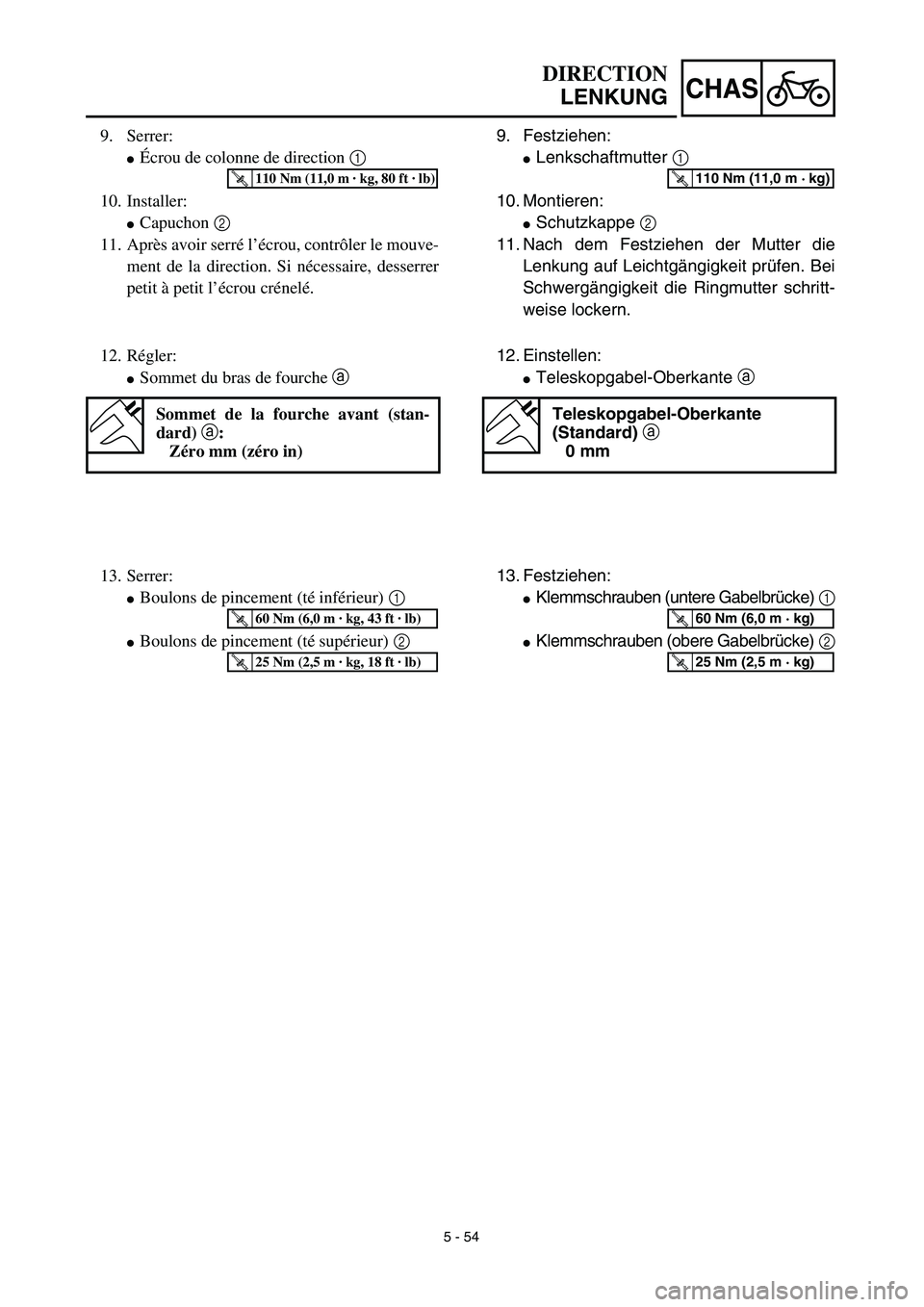
7. Install:
�Upper bracket 1
�Steering stem nut 2
�Starter knob bracket 3
NOTE:
Do not tighten the steering stem nut yet.
T R..10 Nm (1.0 m · kg, 7.2 ft · lb)
8. Install:
�Front forks 1
NOTE:
�Temporarily tighten the pinch bolts (lower
bracket) 2.
�Do not tighten the pinch bolts (upper bracket)
yet.
STEERING
Page 473 of 510
5 - 54
CHAS
9. Festziehen:
�Lenkschaftmutter 1
10. Montieren:
�Schutzkappe 2
11. Nach dem Festziehen der Mutter die
Lenkung auf Leichtgängigkeit prüfen. Bei
Schwergängigkeit die Ringmutter schritt-
weise lockern.
T R..110 Nm (11,0 m · kg)
12. Einstellen:
�Teleskopgabel-Oberkante a
Teleskopgabel-Oberkante
(Standard) a
0 mm
13. Festziehen:
�Klemmschrauben (untere Gabelbrücke) 1
�Klemmschrauben (obere Gabelbrücke) 2
T R..60 Nm (6,0 m · kg)
T R..25 Nm (2,5 m · kg)
DIRECTION
LENKUNG
9. Serrer:
�Écrou de colonne de direction 1
10. Installer:
�Capuchon 2
11. Après avoir serré l’écrou, contrôler le mouve-
ment de la direction. Si nécessaire, desserrer
petit à petit l’écrou crénelé.
T R..110 Nm (11,0 m · kg, 80 ft · lb)
12. Régler:
�Sommet du bras de fourche a
Sommet de la fourche avant (stan-
dard) a:
Zéro mm (zéro in)
13. Serrer:
�Boulons de pincement (té inférieur) 1
�Boulons de pincement (té supérieur) 2
T R..60 Nm (6,0 m · kg, 43 ft · lb)
T R..25 Nm (2,5 m · kg, 18 ft · lb)