Page 223 of 510
 4 - 7
ENG
CARBURATEUR
VERGASER
Drosselventil
1. Kontrollieren:
�Freigängigkeit
Stick → Reparieren oder erneuern.
HINWEIS:
Drosselventil 1 in den Vergaser hineinschie-
ben und auf Freigängigkeit p")
4 - 7
ENG
CARBURATEUR
VERGASER
Drosselventil
1. Kontrollieren:
�Freigängigkeit
Stick → Reparieren oder erneuern.
HINWEIS:
Drosselventil 1 in den Vergaser hineinschie-
ben und auf Freigängigkeit prüfen.
Düsennadel
1. Kontrollieren:
�Düsennadel 1
Verbiegung/Verschleiß → Erneuern.
�Clip-Nut
Spiel/Verschleiß → Erneuern.
�Clip-Position
Kraftstoffstand
1. Messen:
�Kraftstoffstand a
Nicht vorschriftsmäßig → Einstellen.
Standard-Clip-Position
Nut Nr.2
Kraftstoffstand
6,0–7,0 mm
Unterhalb der Schwimmerkam-
mer-Dichtfläche
Arbeitsschritte
�Kraftstoffstandmesser 1 an die Schwim-
merkammer anschließen.
Kraftstoffstandmesser
YM-1312-A/90890-01312
�Kraftstoffstandmesser senkrecht neben die
Schwimmerkammer-Dichtfläche halten.
�Die Ablaßschraube lockern.
�Kraftstoffstand mit dem Kraftstoffstand-
messer messen.
HINWEIS:
Vergaser und Kraftstoffstandmesser müs-
sen sich beim Messen des Kraftstoffstands
in senkrechter Stellung befinden.
�Falls der Kraftstoffstand nicht korrekt ist,
Nadelventilsitz und Nadelventil prüfen.
�Falls ein Bauteil verschlissen ist, beide
Teile erneuern.
�Falls beide Bauteile in Ordnung sind, kann
der Schwimmerstand durch leichtes Bie-
gen des Schwimmerhabels b eingestellt
werden.
�Kraftstoffstand erneut messen.
Boisseau
1. Contrôler:
�Souplesse du mouvement
Calage → Réparer ou remplacer.
N.B.:
Introduire le boisseau 1 dans le carburateur et con-
trôler le mouvement correct.
Aiguille
1. Examiner:
�Aiguille 1
Déformations/usure → Remplacer.
�Gorge de l’agrafe
Jeu/usure → Remplacer.
�Position d’agrafe
Niveau de carburant
1. Mesurer:
�Niveau de carburant a
Hors spécifications → Régler.
Position standard de l’agrafe:
Gorge n˚2
Niveau de carburant:
6,0 à 7,0 mm (0,24 à 0,28 in)
en dessous du plan de joint de la
cuve à niveau constant
Étapes de la mesure et du réglage:
�Fixer la jauge du niveau de carburant 1 à la
cuve à niveau constant.
Jauge de niveau de carburant:
YM-1312-A/90890-01312
�Maintenir la jauge à côté du plan de joint de la
cuve à niveau constant en veillant à ce qu’elle
soit à la verticale.
�Desserrer la vis de vidange.
�Contrôler le niveau de carburant à l’aide de la
jauge.
N.B.:
Mesurer le niveau du carburant en maintenant à
la fois le carburateur et la jauge de niveau à la
verticale.
�Si le niveau de carburant est incorrect, contrô-
ler le pointeau et son siège.
�Si l’un de ces composants est usé, les rempla-
cer tous les deux.
�Si ces deux pièces sont en bon état, régler le
niveau du flotteur en courbant légèrement sa
languette b.
�Vérifier à nouveau le niveau de carburant.
Page 236 of 510
4 - 14
ENGCYLINDER HEAD
REMOVAL POINTS
Cylinder head
1. Align:
�“I” mark
(with stationary pointer)
Checking steps:
�Turn the crankshaft counterclockwise with
a wrench.
�Align the “I” mark a on the rotor with the
stationary pointer b on the crankcase
cover. When the “I” mark is aligned with
the stationary pointer, the piston is at the
Top Dead Center (T.D.C.).
NOTE:
In order to be sure that the piston is at Top
Dead Center, the match mark c on the
camshaft sprocket must align with the sta-
tionary pointer d on the cylinder head as
shown in the illustration.
2. Loosen:
�Camshaft sprocket bolt 1
NOTE:
Remove the bolt while holding the rotor nut
with a wrench.
3. Remove:
�Bolt (timing chain tensioner cap) 1
�Bolt (timing chain tensioner) 2
�Timing chain tensioner 3
Page 242 of 510
4 - 17
ENGCYLINDER HEAD
3. Install:
�Timing chain
�Camshaft sprocket
4. Install:
�Washer
�Bolt (camshaft sprocket)
NOTE:
Temporarily tighten the bolt (camshaft sprocket)
at this point. Installation steps:
�Turn the crankshaft counterclockwise with
a wrench.
�Align the “I” mark a on the rotor with the
stationary pointer b on the crankcase
cover.
�Align the match mark c on the camshaft
sprocket with the stationary pointer d on
the cylinder head.
�Fit the timing chain 1 onto camshaft
sprocket 2 and install the camshaft
sprocket on the camshaft.
NOTE:
When installing the camshaft sprocket, keep
the timing chain as tense as possible on the
exhaust side.
CAUTION:
Do not turn the crankshaft during instal-
lation of the camshaft. Damage or
improper valve timing will result.
�Remove the safety wire from the timing
chain.
Page 244 of 510
4 - 18
ENGCYLINDER HEAD
5. Install:
�Timing chain tensioner
6. Turn:
�Crankshaft
Counterclockwise several turns
7. Check:
�Rotor “I” mark
Align with the crankcase stationary
pointer.
�Camshaft match mark
Align with the cylinder head stationary
pointer.
Out of alignment → Adjust. Installation steps:
�While pressing the tensioner rod lightly
with fingers, use a thin screwdriver and
wind the tensioner rod up fully clockwise.
�With the rod fully wound, install the gasket
1 and the chain tensioner 2, and tighten
the bolts 3 to the specified torque.
T R..
Bolt (chain tensioner):
10 Nm (1.0 m • kg, 7.2 ft • lb)
�Release the screwdriver, check the ten-
sioner rod to come out and tighten the
gasket 4 and the cap bolt 5 to the speci-
fied torque.
T R..
Cap bolt (timing chain tensioner):
8 Nm (0.8 m • kg, 5.8 ft • lb)
8. Tighten:
�Bolt 1
NOTE:
Tighten the bolt while holding the rotor nut with
a wrench.
T R..20 Nm (2.0 m · kg, 14 ft · lb)
Page 290 of 510
4 - 41
ENGCLUTCH AND PRIMARY DRIVEN GEAR
EC498100
PRIMARY DRIVEN GEAR
Extent of removal:1 Primary driven gear removal2 Primary drive gear removal
Extent of removal Order Part name Q’ty Remarks
PRIMARY DRIVEN GEAR
REMOVAL
1 Nut (clutch boss) 1
Use special tool.
Refer to “REMOVAL POINTS”. 2 Lock washer 1
3 Clutch boss 1
4 Thrust plate 1
5 Primary driven gear 1
6 Thrust plate 1
7 Conical spring washer 1
8 Nut (primary drive gear) 1
Refer to “REMOVAL POINTS”.
9 Primary drive gear 1
10Straight key
1
2
1
Page 294 of 510
4 - 43
ENGCLUTCH AND PRIMARY DRIVEN GEAR
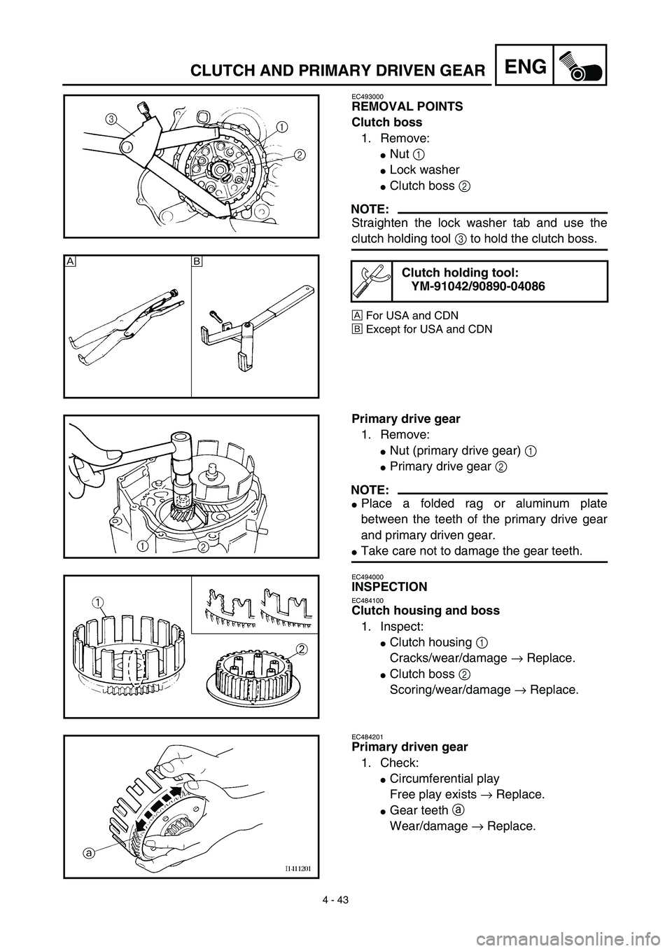
EC493000
REMOVAL POINTS
Clutch boss
1. Remove:
�Nut 1
�Lock washer
�Clutch boss 2
NOTE:
Straighten the lock washer tab and use the
clutch holding tool 3 to hold the clutch boss.
ÅFor USA and CDN
ıExcept for USA and CDN
Clutch holding tool:
YM-91042/90890-04086Å
ı
Primary drive gear
1. Remove:
�Nut (primary drive gear) 1
�Primary drive gear 2
NOTE:
�Place a folded rag or aluminum plate
between the teeth of the primary drive gear
and primary driven gear.
�Take care not to damage the gear teeth.
EC494000
INSPECTION
EC484100
Clutch housing and boss
1. Inspect:
�Clutch housing 1
Cracks/wear/damage → Replace.
�Clutch boss 2
Scoring/wear/damage → Replace.
EC484201
Primary driven gear
1. Check:
�Circumferential play
Free play exists → Replace.
�Gear teeth a
Wear/damage → Replace.
Page 300 of 510
4 - 46
ENGCLUTCH AND PRIMARY DRIVEN GEAR
Clutch
1. Install:
�Conical spring washer 1
�Thrust plate 2
�Primary driven gear 3
�Thrust plate 4
�Clutch boss 5
2. Install:
�Lock washer
�Nut (clutch boss) 1
NOTE:
Use the clutch holding tool 2 to hold the clutch
boss.
ÅFor USA and CDN
ıExcept for USA and CDN
3. Bend:
�Lock washer tab
Clutch holding tool:
YM-91042/90890-04086
New
T R..60 Nm (6.0 m · kg, 43 ft · lb)
Å
ı
4. Install:
�Friction plate 1
�Clutch plate 2
NOTE:
�Install the clutch plates and friction plates
alternately on the clutch boss, starting with a
friction plate and ending with a friction plate.
�Apply the engine oil on the friction plates and
clutch plates.
�Be sure to install a clutch plate with projec-
tion a offset approximately 90˚ from previ-
ous plates projection. Continue this
procedure in a clockwise direction until all
clutch plates are installed.
Page 304 of 510
4 - 48
ENGCLUTCH AND PRIMARY DRIVEN GEAR
9. Adjust:
�Push lever position
Adjustment steps:
�Loosen the locknut 1.
�Turn the push rod 1 2 clockwise or coun-
terclockwise to match alignment marks.
�Hold the push rod 1 to prevent it from
moving and tighten the locknut to specifi-
cation.
�Tighten the locknut 1.
T R..
Locknut:
8 Nm (0.8 m • kg, 5.8 ft • lb)
10. Install:
�Dowel pins
�Gasket (right crankcase cover)
�Right crankcase cover
�Bolts (right crankcase cover)
NOTE:
�Apply Quick gasket® (YAMAHA Bond
No.1215) to end of the right crankcase cover
bolts, as shown.
�Tighten the bolts in stages, using a criss-
cross pattern.
Quick gasket®:
ACC-QUICK-GS-KT
YAMAHA Bond No.1215:
90890-85505
New
T R..10 Nm (1.0 m · kg, 7.2 ft · lb)
11. Install:
�Kickstarter crank 1
�Nut (kickstarter crank) 2
NOTE:
Install the kickstarter crank so that there is 5 ~
10 mm (0.2 ~ 0.4 in) a between the kickstarter
crank and the right crankcase cover.
T R..50 Nm (5.0 m · kg, 36 ft · lb)


 4 - 41
ENGCLUTCH AND PRIMARY DRIVEN GEAR
EC498100
PRIMARY DRIVEN GEAR
Extent of removal:1 Primary driven gear removal2 Primary drive gear removal
Extent of removal Order Part name Q’ty Remarks
PRIMA")