Page 324 of 510
4 - 58
ENGCDI MAGNETO
EC4L0000
CDI MAGNETO
Extent of removal:1 CDI magneto removal
Extent of removal Order Part name Q’ty Remarks
CDI MAGNETO REMOVAL
Preparation for removal Seat and fuel tank Refer to “SAET, FUEL TANK AND SIDE
COVERS” section.
Drain the engine oil Refer to “ENGINE OIL REPLACEMENT”
section in the CHAPTER 3.
Drive sprocket cover Refer to “ENGINE REMOVAL” section.
1 CDI magneto lead 1
2 Left crankcase cover 1
3 Nut (rotor) 1
Use special tool.
Refer to “REMOVAL POINTS”.
4 Rotor 1
5 Woodruff key 1
6 Pickup coil 1
7 Lead guide 1
8Stator
1
1
Page 330 of 510
4 - 61
ENGENGINE REMOVAL
ENGINE REMOVAL
Extent of removal:1 Engine removal
Extent of removal Order Part name Q’ty Remarks
ENGINE REMOVAL
Preparation for removal Hold the machine by placing the
suitable stand under the frame.
Seat, fuel tank and side covers Refer to “SEAT, FUEL TANK AND SIDE
COVERS” section.
Carburetor Refer to “CARBURETOR” section.
Muffler Refer to “MUFFLER” section.
Clutch cable Disconnect at engine side.
Spark plug cap
Disconnect the CDI magneto
lead.
Drain the engine oil. Refer to “ENGINE OIL REPLACEMENT”
section in the CHAPTER 3.
Page 362 of 510
4 - 77
ENGTRANSMISSION, SHIFT CAM AND SHIFT FORK
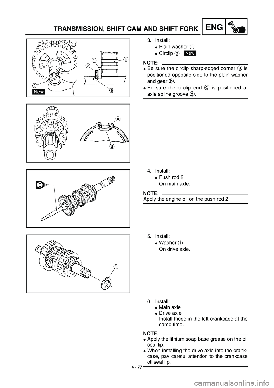
3. Install:
�Plain washer 1
�Circlip 2
NOTE:
�Be sure the circlip sharp-edged corner a is
positioned opposite side to the plain washer
and gear b.
�Be sure the circlip end c is positioned at
axle spline groove d.
New
4. Install:
�Push rod 2
On main axle.
NOTE:
Apply the engine oil on the push rod 2.
5. Install:
�Washer 1
On drive axle.
6. Install:
�Main axle
�Drive axle
Install these in the left crankcase at the
same time.
NOTE:
�Apply the lithium soap base grease on the oil
seal lip.
�When installing the drive axle into the crank-
case, pay careful attention to the crankcase
oil seal lip.
Page 364 of 510
4 - 78
ENGTRANSMISSION, SHIFT CAM AND SHIFT FORK
Shift cam and shift fork
1. Install:
�Shift fork 1 (L) 1
�Shift fork 2 (C) 2
�Shift fork 3 (R) 3
NOTE:
�Mesh the shift fork #1 (L) with the 2nd wheel
gear and #3 (R) with the 4th wheel gear on
the drive axle.
�Mesh the shift fork #2 (C) with the 3rd pinion
gear on the main axle.
2. Install:
�Shift cam 1
NOTE:
Apply the engine oil on the shift cam.
3. Install:
�Shift fork guide bar 1 (short) 1
�Shift fork guide bar 2 (long) 2
NOTE:
�Apply the engine oil on the guide bars.
�Be sure the long bar is inserted into the shift
forks #1 and #3 and the short one into #2.
4. Check:
�Shifter operation
�Transmission operation
Unsmooth operation → Repair.
Page 366 of 510
5 - 1
CHAS
FRONT WHEEL AND FRONT BRAKE (TT-R125)
EC500000
CHASSIS
FRONT WHEEL AND FRONT BRAKE (TT-R125)
Extent of removal:
1
Front wheel removal
2
Wheel bearing removal
3
Brake shoe plate assembly removal and disassembly
Extent of removal Order Part name Q’ty Remarks
Preparation for removal
FRONT WHEEL AND DRUM
BRAKE
Hold the machine by placing the
suitable stand under the engine.
WARNING
Support the machine securely so there is no
danger of it falling over.
1 Brake cable holder 1
2 Brake cable 1 Disconnect at the lever side, first.
3 Axle nut 1
4 Wheel axle 1
5 Front wheel 1
6 Collar set 1
7 Brake shoe plate assembly 1
8 Oil seal 1
9 Wheel bearing 2 Refer to “REMOVAL POINTS”.
10Spacer
1
2
3
1
Page 380 of 510
5 - 8
CHAS
FRONT WHEEL (TT-R125LW)
Extent of removal:1 Front wheel removal2 Wheel bearing removal
3 Brake disc removal
Extent of removal Order Part name Q’ty Remarks
Preparation for removalFRONT WHEEL REMOVAL
Hold the machine by placing the
suitable stand under the engine.
WARNING
Support the machine securely so there is nodanger of it falling over.
1 Axle nut 1
2 Washer 1
3 Wheel axle 1
4 Front wheel 1
5 Collar 2
6 Oil seal 2
7 Wheel bearing 2 Refer to “REMOVAL POINTS”.
8 Spacer 1
9Brake disk
1
2
31
3
FRONT WHEEL (TT-R125LW)
Page 496 of 510
6 - 1
–+ELEC
* The illustration shows the TT-R125LW
ELECTRICAL COMPONENTS AND WIRING DIAGRAM
EC600000
ELECTRICAL
EC610000
ELECTRICAL COMPONENTS AND WIRING DIAGRAM
EC611000
ELECTRICAL COMPONENTS
1CDI unit
2Engine stop switch
3Ignition coil
4CDI magneto
5Spark plugCOLOR CODE
B...................... Black
Br .................... Brown
G ..................... Green
O ..................... Orange
R ..................... Red
W..................... WhiteB/R .................. Black/Red
B/W ................. Black/White
G/L .................. Green/Blue
G/W ................. Green/White
W/L .................. White/Blue
W/R ................. White/Red
EC612000
WIRING DIAGRAM
Page 498 of 510
–+ELEC
6 - 2
IGNITION SYSTEM
EC620000
IGNITION SYSTEM
INSPECTION STEPS
Use the following steps for checking the possibility of the malfunctioning engine being attributable to
ignition system failure and for checking the spark plug which will not spark.
*marked: Only when the ignition checker is used.
NOTE:
�Remove the following parts before inspection.
1) Seat
2) Fuel tank
�Use the following special tools in this inspection.
Spark gap test*Clean or replace
spark plug.
Check entire ignition
system for connection.Repair or replace.
Check engine stop switch. Replace.
Check ignition coil. Primary coil Replace.
Secondary coil Replace.
Check CDI magneto. Pickup coil Replace.
Charging coil Replace.
Replace CDI unit.
Dynamic spark tester:
YM-34487
Ignition checker:
90890-06754Pocket tester:
YU-3112-C/90890-03112
No Spark
OK
OK
OK
OK
Spark
No good
No good
No good
No good
No good
No good
 4 - 58
ENGCDI MAGNETO
EC4L0000
CDI MAGNETO
Extent of removal:1 CDI magneto removal
Extent of removal Order Part name Q’ty Remarks
CDI MAGNETO REMOVAL
Preparation for removal Seat and fuel tank Refe")
 4 - 61
ENGENGINE REMOVAL
ENGINE REMOVAL
Extent of removal:1 Engine removal
Extent of removal Order Part name Q’ty Remarks
ENGINE REMOVAL
Preparation for removal Hold the machine by placing the
suita")


5 - 1
CHAS
FRONT WHEEL AND FRONT BRAKE (TT-R125)
EC500000
CHASSIS
FRONT WHEEL AND FRONT BRAKE (TT-R125)
Extent of removal:
1
Front wheel removal
2
Wheel bearing removal
3
Brake")
 5 - 8
CHAS
FRONT WHEEL (TT-R125LW)
Extent of removal:1 Front wheel removal2 Wheel bearing removal
3 Brake disc removal
Extent of removal Order Part name Q’ty Remarks
Preparation for removalFRONT WHE")
 6 - 1
–+ELEC
* The illustration shows the TT-R125LW
ELECTRICAL COMPONENTS AND WIRING DIAGRAM
EC600000
ELECTRICAL
EC610000
ELECTRICAL COMPONENTS AND WIRING DIAGRAM
EC611000
ELECTRICAL COMPONENTS
1CDI")
 –+ELEC
6 - 2
IGNITION SYSTEM
EC620000
IGNITION SYSTEM
INSPECTION STEPS
Use the following steps for checking the possibility of the malfunctioning engine being attributable to
ignition system failure")