Page 166 of 510
 3 - 8
INSP
ADJ
ENGINE OIL LEVEL INSPECTION
4. Check:
�Oil level
Oil level should be between maximum
a and minimum b marks.
Oil level is low → Add oil to proper
level.
NOTE:
When inspecting the oil l")
3 - 8
INSP
ADJ
ENGINE OIL LEVEL INSPECTION
4. Check:
�Oil level
Oil level should be between maximum
a and minimum b marks.
Oil level is low → Add oil to proper
level.
NOTE:
When inspecting the oil level, do not screw the
dipstick into the oil tank. Insert the gauge
lightly.
(For USA and CDN)
CAUTION:
�Do not add any chemical additives.
Engine oil also lubricates the clutch and
additives could cause clutch slippage.
�Do not allow foreign material to enter the
crankcase.
Recommended oil:
At –10 ˚C (10 ˚F) or higher Å:
Yamalube 4 (10W-30) or SAE
10W-30 type SE motor oil
At 5 ˚C (40 ˚F) or higher ı:
Yamalube 4 (20W-40) or SAE
20W-40 type SE motor oil
(Except for USA and CDN)
CAUTION:
�Do not add any chemical additives or use
oils with a grade of CD a or higher.
�Do not use oils labeled “ENERGY CON-
SERVING II” b or higher. Engine oil also
lubricates the clutch and additives could
cause clutch slippage.
�Do not allow foreign materials to enter the
crankcase.
Recommended oil:
Refer to the following chart for
selection of oils which are suited
to the atmospheric temperatures.
Recommended engine oil classi-
fication:
API STANDARD:
API “SE” or higher grade
(Designed primarily for motor-
cycles)
Page 168 of 510
3 - 9
INSP
ADJ
ENGINE OIL REPLACEMENT
5. Install:
�Dipstick
6. Start the engine and let it warm up for
several minutes.
7. Turn off the engine and inspect the oil
level once again.
NOTE:
Wait a few minutes until the oil settles before
inspecting the oil level.
ENGINE OIL REPLACEMENT
1. Start the engine and warm it up for sev-
eral minutes and wait for five minute.
2. Place the machine on a level place and
hold it on upright position by placing the
suitable stand under the engine.
3. Place a suitable container under the
engine.
4. Remove:
�Oil drain bolt 1
�Dipstick 2
Drain the engine oil.
5. Install:
�Copper washer
�Oil drain bolt 1
New
T R..20 Nm (2.0 m · kg, 14 ft · lb)
6. Fill:
�Engine oil
7. Check:
�Oil leakage
8. Check:
�Engine oil level
9. Install:
�Dipstick 2
Oil capacity:
Periodic oil change:
1.0 L (0.88 Imp qt, 1.06 US qt)
Page 170 of 510
 3 - 10
INSP
ADJOIL PRESSURE INSPECTION/PILOT AIR SCREW
ADJUSTMENT/ENGINE IDLING SPEED ADJUSTMENT
OIL PRESSURE INSPECTION
1. Check:
�Oil pressure
Checking steps:
�Slightly loosen the oil pressure check")
3 - 10
INSP
ADJOIL PRESSURE INSPECTION/PILOT AIR SCREW
ADJUSTMENT/ENGINE IDLING SPEED ADJUSTMENT
OIL PRESSURE INSPECTION
1. Check:
�Oil pressure
Checking steps:
�Slightly loosen the oil pressure check bolt
1.
�Start the engine and keep it idling until oil
starts to seep from the oil pressure check
bolt. If no oil comes out after one minute,
turn the engine off so it will not seize.
�Check oil passages and oil pump for dam-
age or leakage.
�Start the engine after solving the prob-
lem(s) and recheck the oil pressure.
�Tighten the oil pressure check bolt.
T R..
Oil pressure check bolt:
7 Nm (0.7 m • kg, 5.1 ft • lb)
PILOT AIR SCREW ADJUSTMENT
1. Adjust:
�Pilot air screw 1
Adjustment steps:
NOTE:
To optimize the fuel flow at a smaller throttle
opening, each machine’s pilot air screw has
been individually set at the factory. Before
adjusting the pilot air screw, turn it in fully
and count the number of turns. Record this
number as the factory-set number of turns
out.
�Screw in the pilot air screw until it is lightly
seated.
�Back out by the specified number of turns.
Pilot air screw:
2-1/2 ~ 3-1/2 turns out (example)
ENGINE IDLING SPEED ADJUSTMENT
1. Start the engine and thoroughly warm it
up.
2. Attach:
�Inductive tachometer
To spark plug lead.
3. Adjust:
�Engine idling speed
Page 194 of 510
 3 - 22
INSP
ADJ
DRIVE CHAIN SLACK ADJUSTMENT
6. Lubricate:
�Drive chain
Drive chain lubricant:
SAE 10W-30 motor oil or suit-
able chain lubricants
DRIVE CHAIN SLACK ADJUSTMENT
1. Elevate the rear whee")
3 - 22
INSP
ADJ
DRIVE CHAIN SLACK ADJUSTMENT
6. Lubricate:
�Drive chain
Drive chain lubricant:
SAE 10W-30 motor oil or suit-
able chain lubricants
DRIVE CHAIN SLACK ADJUSTMENT
1. Elevate the rear wheel by placing the
suitable stand under the engine.
2. Check:
�Drive chain slack a
In the center between the drive axle
and rear wheel axle.
Out of specification → Adjust.
NOTE:
Before checking and/or adjusting, rotate the
rear wheel through several revolutions and
check the slack several times to find the tight-
est point. Check and/or adjust chain slack with
rear wheel in this “tight chain” position.
Drive chain slack:
35 ~ 50 mm (1.4 ~ 2.0 in)
3. Adjust:
�Drive chain slack
Drive chain slack adjustment steps:
�Loosen the axle nut 1.
�Turn both drive chain pullers 2 the same
amount a and adjust them to the stopper
in the same position so that the drive
chain slack is within the specified limits.
CAUTION:
Too small chain slack will overload the
engine and other vital parts; keep the
slack within the specified limits.
�Tighten the axle nut while pushing down
the drive chain.
T R..
Axle nut:
60 Nm (6.0 m • kg, 43 ft • lb)
Page 196 of 510
3 - 23
INSP
ADJ
FRONT FORK INSPECTION/
REAR SHOCK ABSORBER ASSEMBLY INSPECTION/
REAR SHOCK ABSORBER SPRING PRELOAD ADJUSTMENT
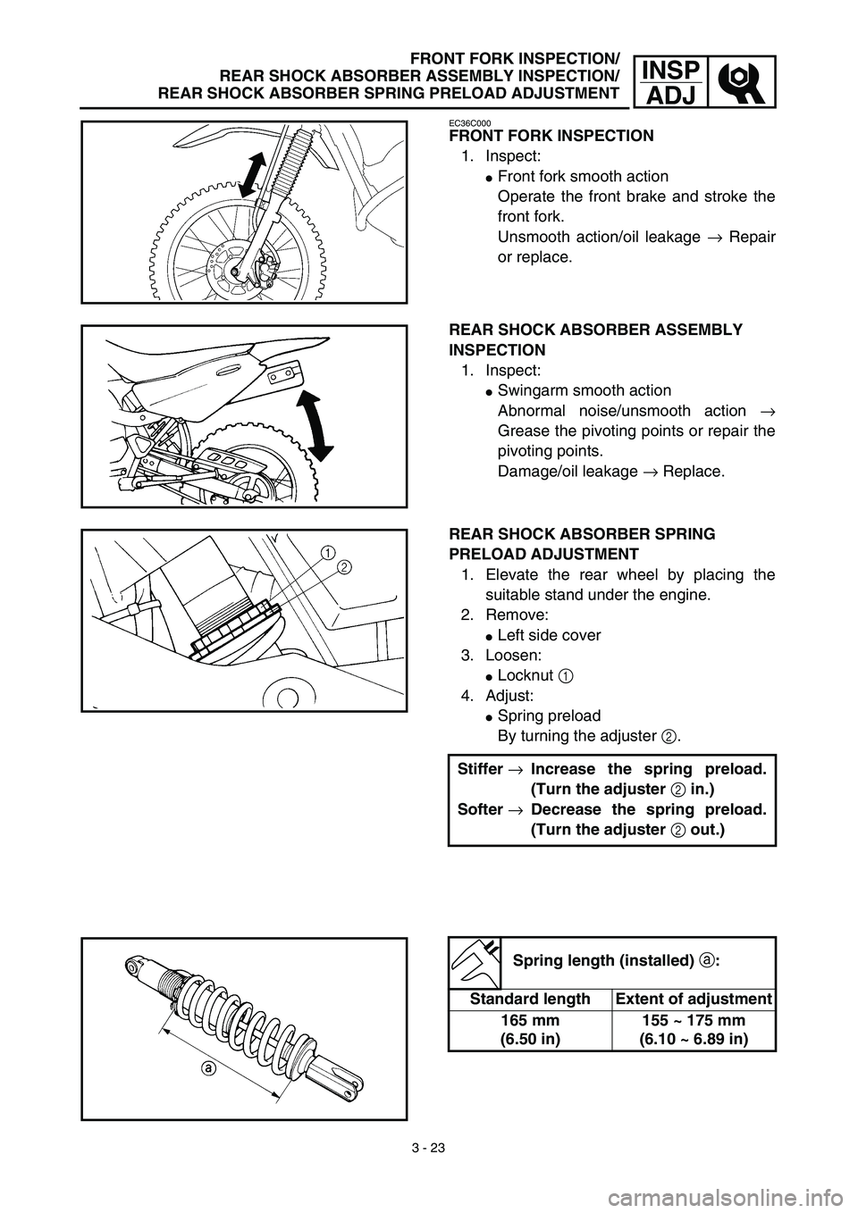
EC36C000
FRONT FORK INSPECTION
1. Inspect:
�Front fork smooth action
Operate the front brake and stroke the
front fork.
Unsmooth action/oil leakage → Repair
or replace.
REAR SHOCK ABSORBER ASSEMBLY
INSPECTION
1. Inspect:
�Swingarm smooth action
Abnormal noise/unsmooth action →
Grease the pivoting points or repair the
pivoting points.
Damage/oil leakage → Replace.
REAR SHOCK ABSORBER SPRING
PRELOAD ADJUSTMENT
1. Elevate the rear wheel by placing the
suitable stand under the engine.
2. Remove:
�Left side cover
3. Loosen:
�Locknut 1
4. Adjust:
�Spring preload
By turning the adjuster 2.
Stiffer →Increase the spring preload.
(Turn the adjuster 2 in.)
Softer →Decrease the spring preload.
(Turn the adjuster 2 out.)
Spring length (installed) a:
Standard length Extent of adjustment
165 mm
(6.50 in)155 ~ 175 mm
(6.10 ~ 6.89 in)
Page 240 of 510
4 - 16
ENGCYLINDER HEAD
Warpage limit:
0.03 mm (0.0012 in)
�If the warpage is out of specification,
resurface the cylinder head.
�Place #400 ~ 600 grit wet sandpaper on
the surface plate, and re-surface the head
using a figure-eight sanding pattern.
NOTE:
Rotate the cylinder head several times to
avoid removing too much material from one
side.
ASSEMBLY AND INSTALLATION
Cylinder head
1. Install:
�Dowel pin 1
�Gasket 2 New
2. Install:
�Cylinder head
�Copper washer
�Bolt (cylinder head)
NOTE:
�Apply Quick gasket® (YAMAHA Bond
No.1215) on end of the cylinder head bolts
(M6), as shown.
�Apply the engine oil on the contact surfaces of
the bolts (cylinder head) and copper washers.
�Follow the numerical order shown in the illus-
tration. Tighten the bolts in two stages.
Quick gasket®:
ACC-QUICK-GS-KT
YAMAHA Bond No.1215:
90890-85505
T R..M8 22 Nm (2.2 m · kg, 16 ft · lb)
M6 10 Nm (1.0 m · kg, 7.2 ft · lb)
Page 246 of 510
4 - 19
ENGCYLINDER HEAD
9. Check:
�Valve clearance
Out of specification → Adjust.
Refer to “VALVE CLEARANCE
INSPECTION AND ADJUSTMENT”
section in the CHAPTER 3.
10. Apply:
�Engine oil
On camshaft.
11. Install:
�Tappet cover 1
�Cylinder head side cover 2
T R..18 Nm (1.8 m · kg, 13 ft · lb)
T R..10 Nm (1.0 m · kg, 7.2 ft · lb)
12. Install:
�Timing mark accessing screw 1
�Crankshaft end accessing screw 2
T R..7 Nm (0.7 m · kg, 5.1 ft · lb)
T R..7 Nm (0.7 m · kg, 5.1 ft · lb)
13. Install:
�Spark plug
�Engine bracket
T R..13 Nm (1.3 m · kg, 9.4 ft · lb)
T R..40 Nm (4.0 m · kg, 29 ft · lb)
Page 252 of 510
4 - 22
ENGCAMSHAFT AND ROCKER ARMS
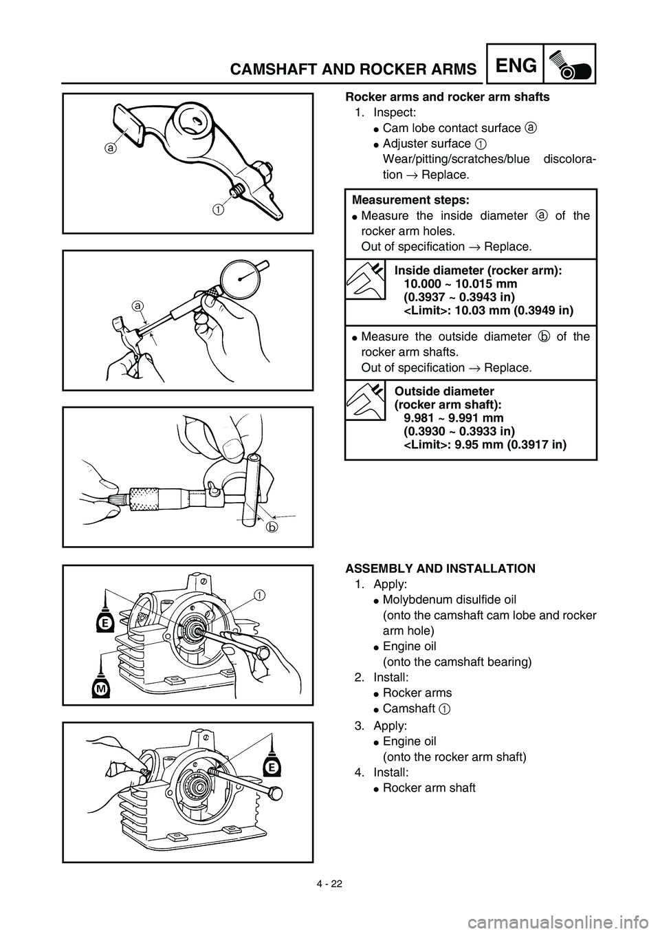
Rocker arms and rocker arm shafts
1. Inspect:
�Cam lobe contact surface a
�Adjuster surface 1
Wear/pitting/scratches/blue discolora-
tion → Replace.
Measurement steps:
�Measure the inside diameter a of the
rocker arm holes.
Out of specification → Replace.
Inside diameter (rocker arm):
10.000 ~ 10.015 mm
(0.3937 ~ 0.3943 in)
: 10.03 mm (0.3949 in)
�Measure the outside diameter b of the
rocker arm shafts.
Out of specification → Replace.
Outside diameter
(rocker arm shaft):
9.981 ~ 9.991 mm
(0.3930 ~ 0.3933 in)
: 9.95 mm (0.3917 in)
ASSEMBLY AND INSTALLATION
1. Apply:
�Molybdenum disulfide oil
(onto the camshaft cam lobe and rocker
arm hole)
�Engine oil
(onto the camshaft bearing)
2. Install:
�Rocker arms
�Camshaft 1
3. Apply:
�Engine oil
(onto the rocker arm shaft)
4. Install:
�Rocker arm shaft