Page 25 of 116
3-8
INSTRUMENT AND CONTROL FUNCTIONS
3
Clock
To set the clock
1. Push the “SELECT” button until
the clock is displayed.
2. Push the “SELECT” button and
“RESET” button together for at
least two seconds.
4. Push the “SELECT” button, and
the minute digits will start flash-
ing.
5. Push the “RESET” button to set
the minutes.
6. Push the “SELECT” button and
then release it to start the clock.3. When the hour digits start flash-
ing, push the “RESET” button to
set the hours.
5SJ-28199-E1 7/11/02 11:03 AM Page 23
Page 26 of 116

3-9
Outside temperature display
This display shows the outside tem-
perature from -10.0 °C to 50.0 °C in
0.5 °C increments.
INSTRUMENT AND CONTROL FUNCTIONS
3
8When the outside temperature
falls below -10.0 °C, “– – °C ” is
displayed.
8When the outside temperature
climbs above 50.0 °C, “50.0”
flashes.
NOTE:
8If “– – °C” is displayed or “50.0”
flashes while the outside temper-
ature is between -10.0 °C and
50.0 °C, there is a problem with
the electrical circuit. Have a
Yamaha dealer check or repair
the electric circuit.
8The accuracy of the temperature
reading may be affected when
riding slowly (approximately
under 20 km/h) or when stopped
at traffic signals, railroad cross-
ings, etc.
Voltage display
This display shows the battery volt-
age.
ECA00135
cC
If the voltage display indicates
“LO” or “HI”, there may be trouble
with the battery charging circuit or
the battery may be faulty. If “LO”
or “HI” appears in the display,
have a Yamaha dealer check or
repair the scooter.
5SJ-28199-E1 7/11/02 11:03 AM Page 24
Page 27 of 116

3-10
INSTRUMENT AND CONTROL FUNCTIONS
3
EAU00109
Anti-theft alarm (optional)
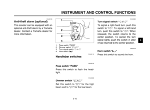
Anti-theft alarm (optional)This scooter can be equipped with an
optional anti-theft alarm by a Yamaha
dealer. Contact a Yamaha dealer for
more information.
EAU03889
Turn signal switch “4/6”Turn signal switchTo signal a right-hand turn, push this
switch to “6”. To signal a left-hand
turn, push this switch to “4”. When
released, the switch returns to the
center position. To cancel the turn
signal lights, push the switch in after
it has returned to the center position.
EAU00129
Horn switch “*”Horn switchPress this switch to sound the horn.EAU00118
Handlebar switches
Handlebar switchesEAU00120
Pass switch “PASS”Pass switchPress this switch to flash the head-
light.
EAU03888
Dimmer switch “&/%”Dimmer switchSet this switch to “&” for the high
beam and to “%” for the low beam.
1
2
3
4
1. Pass switch “PASS”
2. Dimmer switch “&/%”
3. Turn signal switch “4/6”
4. Horn switch “*”
5SJ-28199-E1 7/11/02 11:03 AM Page 25
Page 28 of 116
3-11
EAU03890
Engine stop switch “#/$”Engine stop switchSet this switch to “#” before starting
the engine. Set this switch to “$” to
stop the engine in case of an emer-
gency, such as when the scooter
overturns or when the throttle cable is
stuck.
INSTRUMENT AND CONTROL FUNCTIONS
3
1
2
1. Engine stop switch “#/$”
2. Start switch “,”
EAU03801
Start switch “,”Start switchWith the sidestand up, push this
switch while applying the front or rear
brake to crank the engine with the
starter.
EC000005
cC
See page 5-1 for starting instruc-
tions prior to starting the engine.
EAU03882
Front brake leverBrake lever, frontThe front brake lever is located on
the right handlebar grip. To apply the
front brake, pull this lever toward the
handlebar grip.
1
1. Front brake lever
5SJ-28199-E1 7/11/02 11:03 AM Page 26
Page 29 of 116
3-12
INSTRUMENT AND CONTROL FUNCTIONS
3
EAU00163
Rear brake leverBrake lever, rearThe rear brake lever is located on the
left handlebar grip. To apply the rear
brake, pull this lever toward the han-
dlebar grip.
1
1. Rear brake lever
5SJ-28199-E1 7/11/02 11:03 AM Page 27
Page 30 of 116

3-13
EAU03631
ABSABSThe Yamaha ABS (Anti-lock Brake
System) features a dual electronic
control system, which acts on the
front and rear brakes independently.
The ABS securely controls wheel
lockup during emergency braking on
changing road surfaces and under
various weather conditions, thereby
maximizing tire adhesion and perfor-
mance while providing a smooth
braking action. The ABS is monitored
by an ECU (Electronic Control Unit),
which will have recourse to manual
braking if a malfunction occurs.
INSTRUMENT AND CONTROL FUNCTIONS
3
EW000020
w
8 8
The ABS performs best on
long braking distances.
8 8
On certain (rough or gravel)
roads, the braking distance
may be longer with than with-
out the ABS. Therefore, always
keep a sufficient distance to
the vehicle ahead to match the
riding speed.
NOTE:
8When the ABS is activated, the
brakes are operated in the usual
way. A pulsating action may be
felt at the brake levers, but this
does not indicate a malfunction.
8This ABS has a test mode which
allows the owner to experience
the pulsating at the brake levers
when the ABS is operating.
However, special tools are
required, so please consult your
Yamaha dealer when performing
this test.
5SJ-28199-E1 7/11/02 11:03 AM Page 28
Page 31 of 116
3-14
INSTRUMENT AND CONTROL FUNCTIONS
3 ABS components
1
2
3
4
5
6
7
8
9
10 11 12 13 14 15
1. Front brake hose
2. Rear brake hose
3. ABS warning light
4. Fail-safe relay
5. ECU (Electronic Control Unit)
6. Stop relay
7. Hydraulic Unit (HU)
8. Front brake hose
9. Front wheel sensor rotor
10.Front wheel sensor
11.Fuse boxes
12.ABS test coupler
13.Rear brake hose
14.Rear wheel sensor rotor
15.Rear wheel sensor
5SJ-28199-E1 7/11/02 11:03 AM Page 29
Page 32 of 116
3-15
EAU03090
Fuel tank cap
Fuel tank capTo open the fuel tank cap
1. Open the lid by sliding the lever
forward, and then pull the lever
up.
INSTRUMENT AND CONTROL FUNCTIONS
3
1
2
1. Lid
2. Lever
2. Insert the key into the lock and
turn it clockwise. The lock will be
released and the fuel tank cap
can be removed.
1
1. Fuel tank cap
To install the fuel tank cap
1. Align the match marks, insert the
fuel tank cap into the tank open-
ing, and then push down on the
cap.
2. Turn the key counterclockwise to
the original position, and then
remove it.
3. Close the lid.
EWA00028
w
Be sure that the fuel tank cap is
properly installed and locked
before riding the scooter.
1
1. Match marks
5SJ-28199-E1 7/11/02 11:03 AM Page 30