Page 180 of 2234

ENGINE HOOD/DOOR
TORQUE SPECIFICATION
Part TightenedN�mkgf �cmft �lbf
HOOD
Hood hinge x Hood1313310
Hood h")
031GG±01
±
SERVICE SPECIFICATIONS ENGINE HOOD/DOOR
03±73
AVENSIS REPAIR MANUAL (RM1018E)
ENGINE HOOD/DOOR
TORQUE SPECIFICATION
Part TightenedN�mkgf �cmft �lbf
HOOD
Hood hinge x Hood1313310
Hood hinge x Body5.55649 in.� lbf
Hood lock x Hood8.08271 in.�lbf
FRONT DOOR
Door check x Body3030622
Door check x Door panel5.55646 in.�lbf
Door frame sub±assy rear lower x Door panel8.08271 in.�lbf
Door glass x Front door window regulator5.55649 in.�lbf
Door hinge x Body2626519
Door hinge x Door panel2626519
Door lock x Door panel5.05144 in.�lbf
Door lock striker x Body2323517
Door outside handle cover x Door panel7.07162 in.�lbf
Door outside handle frame x Door panel4.04135 in.�lbf
Outer view mirror x Door panel101027
Window regulator x Door panel8.08271 in.�lbf
REAR DOOR
Door check x Body3030622
Door check x Door panel5.55649 in.�lbf
Door hinge x Body2626519
Door hinge x Door panel2626519
Door lock x Door panel5.05144 in.�lbf
Door lock striker x Body2323517
Door outside handle cover x Door panel4.04135 in.�lbf
Door outside handle frame x Door panel7.07162 in.�lbf
Window division bar sub±assy x Door panel5.55649 in.�lbf
LAGGAGE COMPERTMENT DOOR
Back door striker assy x Body11.51208.0
Luggage compertment door x Hinge7.07062 in.�lbf
Luggage lock assy x Luggage compertment door5.05144 in.�lbf
Luggage compertment outside garnish x Luggage compertment door4.94943 in.�lbf
BACK DOOR (LIFTBACK MODEL)
Back door femaie stopper x Door panel5.55649 in.�lbf
Back door hinge assy x Body19.520014
Back door hinge assy x Door panel19.520014
Back door lock assy x Door panel8.08271 in.�lbf
Back door lock Striker x Body11.51208.0
Back door stay sub±assy x Body7.07162 in.�lbf
Back door stay sub±assy x Door panel2222416
Center stop lamp assy x Door panel5.55649 in.�lbf
BACK DOOR (WAGON MODEL)
Back door femaie stopper x Door panel5.55649 in.�lbf
Back door hinge assy x Body19.520014
Back door hinge assy x Door panel19.520014
Back door lock assy x Door panel8.08271 in.�lbf
Back door lock Striker x Body11.51208.0
Back door stay sub±assy x Body7.07162 in.�lbf
http://vnx.su
Page 181 of 2234
03±74
±
SERVICE SPECIFICATIONS ENGINE HOOD/DOOR
AVENSIS REPAIR MANUAL (RM1018E) Part Tightened
ft�lbf
kgf �cm
N �m
Back door stay sub±assy x Door panel2222416
Center stop lamp assy x Door panel5.55649 in.� lbf
http://vnx.su
Page 193 of 2234
031GY±01
±
SERVICE SPECIFICATIONS EXTERIOR/INTERIOR TRIM
03±75
AVENSIS REPAIR MANUAL (RM1018E)
EXTERIOR/INTERIOR TRIM
TORQUE SPECIFICATION
Part TightenedN�mkgf �cmft �lbf
FUEL LID CONTROL ASSY
Fuel lid control assy x Body8.08271 in.� lbf
REAR BUMPER COVER
Rear bumper cover x Body5.55649 in.�lbf
Rear bumper reinforcement No. 1 x Body11.511 516
BACK DOOR GARNISH OUTSIDE
Back door garnish � Body4.95043 in.�lbf
REAR SPOILER (WAGON MODELS)
Rear spoiler � Body9.89987 in.�lbf
http://vnx.su
Page 231 of 2234
031HO±01
±
SERVICE SPECIFICATIONS WINDSHIELD/WINDOWGLASS/MIRROR
03±69
AVENSIS REPAIR MANUAL (RM1018E)
WINDSHIELD/WINDOWGLASS/MIRROR
TORQUE SPECIFICATION
Part TightenedN�mkgf �cmft �lbf
OUTER REAR VIEW MIRROR ASSY LH
Outer rear view mirrror assy x Front door101027
http://vnx.su
Page 242 of 2234
100FR±01
A79186
±
ENGINE CONTROL SYSTEMECM
10±65
AVENSIS REPAIR MANUAL (RM1018E)
ECM
REPLACEMENT
HINT:
1CD±FTV Engine Type:
Each injector assembly has a characteristic fuel injecting behavior. The ECM stores compensation codes
which are used to optimize fuel injection for the injectors. When replacing t\
he ECM, the compensation codes
must be set to the new ECM.
1.REMOVE GLOVE COMPARTMENT DOOR ASSY (See page 71±11)
2.REMOVE ECM
(a)Disconnect the 4 ECM connectors (1ZZ±FE, 3ZZ±FE,1AZ±FE, 1CD±FTV).
(b)Disconnect the 5 ECM connectors (1AZ±FSE).
(c)Disconnect the wire harness clamp.
(d)Remove the bolt and screw, then remove the ECM.
(e)Remove the 2 screws and the ECM bracket No. 1 from the ECM.
(f)Remove the 2 screws and the ECM bracket No. 2 from the ECM.
3.INSTALL ECM Torque: 5.5 N �m (56 kgf�cm, 49 in. �lbf)
4.INSTALL GLOVE COMPARTMENT DOOR ASSY (See page 71±11)
5.REGISTRATION OF INJECTOR COMPENSATION CODE (1CD±FTV ENGINE TYPE) (See page 05±528)
http://vnx.su
Page 637 of 2234
A77338
A77337
A77336
A57550
Engine Hanger No. 1 Engine Hanger No. 2
±
ENGINE MECHANICAL PARTIAL ENGINE ASSY (1AZ±FE)
14±125
AVENSIS REPAIR MANUAL (RM1018E)
55. SEPARATE ENGINE ROOM RELAY BLOCK NO.2
(a) Remove the nut and disconnect the connector as shown
in the illustration.
56. SEPARATE ENGINE WIRE
(a) Remove the bolt and separate the grand terminal.
(b) Separate the grand terminal connector.
(c) Remove the glove compartment door panel.
(d) Separate the engine wire.
57.SEPARATE STEERING INTERMEDIATE SHAFT ASSY NO.2 (See page 50±9) 58. INSTALL ENGINE HANGERS
(a) Install the engine hanger No. 1 (12281±28010, 28020,28030) with the bolt (91512±61020).
Torque: 38 N �m (387 kgf� cm, 28 ft�lbf)
(b) Install the engine hanger No. 2 (12282±28010, 28020, 28030) with the bolt (91512±61020).
Torque: 38 N �m (387 kgf� cm, 28 ft�lbf)
http://vnx.su
Page 649 of 2234
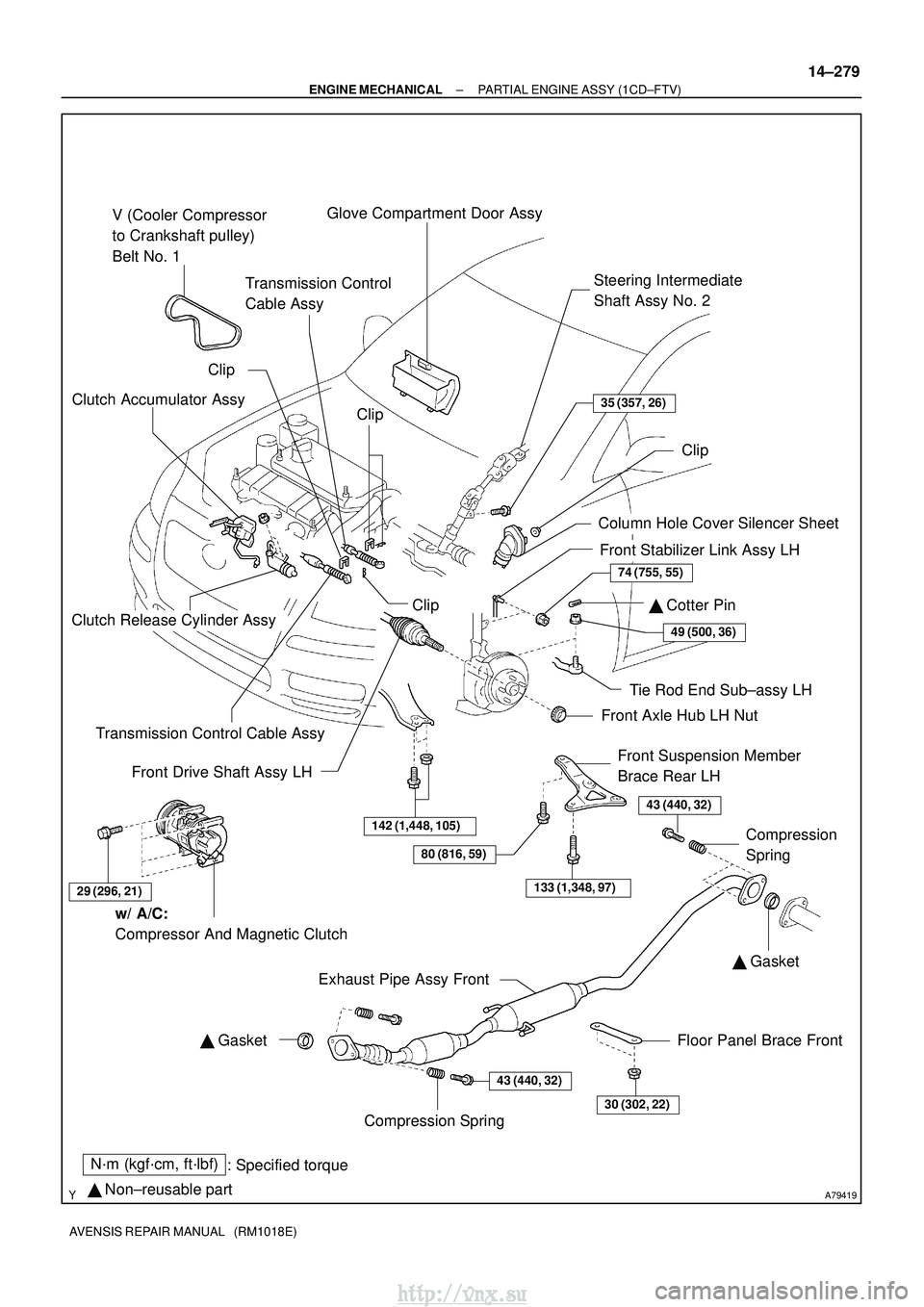
A79419
N´m (kgf´cm, ft´lbf): Specified torque
� Non±reusable part
29 (296, 21)
80 (816, 59)
133 (1,348, 97)
43 (440, 32)
30 (302, 22)
43 (440, 32)
� Gasket
74 (755, 55)
49 (500, 36)
� Gasket
�
Cotter Pin
V (Cooler Compressor
to Crankshaft pulley)
Belt No. 1
Glove Compartment Door Assy
Steering Intermediate
Shaft Assy No. 2
Column Hole Cover Silencer Sheet
Front Stabilizer Link Assy LHClip
Tie Rod End Sub±assy LH
Front Axle Hub LH Nut
Front Suspension Member
Brace Rear LH
Compression
Spring
Floor Panel Brace Front
Exhaust Pipe Assy Front
Compression Spring
w/ A/C:
Compressor And Magnetic Clutch
Front Drive Shaft Assy LH Clip
Transmission Control
Cable Assy
Clip
Clutch Accumulator Assy
Clutch Release Cylinder Assy
Transmission Control Cable Assy
35 (357, 26)
142 (1,448, 105)
Clip
±
ENGINE MECHANICAL PARTIAL ENGINE ASSY (1CD±FTV)
14±279
AVENSIS REPAIR MANUAL (RM1018E)
http://vnx.su
Page 657 of 2234

14±287
AVENSIS REPAIR MANUAL (RM1018E)
24.SEPARATE TRANSMISSION CONTROL CABLE ASSY
(a)Remove the 2 clips and 2 washers, separate the")
A79178
A78277
±
ENGINE MECHANICALPARTIAL ENGINE ASSY(1CD±FTV)
14±287
AVENSIS REPAIR MANUAL (RM1018E)
24.SEPARATE TRANSMISSION CONTROL CABLE ASSY
(a)Remove the 2 clips and 2 washers, separate the control cable assy.
25.REMOVE INJECTOR DRIVER
(a)Remove the 2 nuts which is used to secure the injector driver.
(b)Disconnect the injector driver connector and the harness clamp.
(c)Remove the injector driver.
26.DISCONNECT ENGINE WIRE
(a)Remove the glove compartment door.
(b)Disconnect the engine wire from the ECM and the junc-
tion block.
(c)Pull out the engine wire.
(d)Disconnect the engine wire from engine room junction block.
(e)Remove the bolt and disconnect the wire harness from the body.
27.REMOVE AIR TUBE NO.1
(a)Loosen the hose clamps.
(b)Remove the 2 bolts and nut, and then detach the air tube No. 1.
28.REMOVE CLUTCH ACCUMULATOR ASSY (See page 42±17) SST 09023±00100
29.REMOVE CLUTCH RELEASE CYLINDER ASSY (See page 42±17)
30. REMOVE V (COOLER COMPRESSOR TO CRANKSHAFT PULLEY) BELT NO.1
(See page 14±269)
31. SEPARATE COMPRESSOR AND MAGNETIC CLUTCH (W/ AIR CONDITIONING) (See page 55±86)
HINT:
Secure the hoses off to the side instead of detaching.
32.REMOVE FLOOR PANEL BRACE FRONT (See page 15±10)
33.REMOVE EXHAUST PIPE ASSY FRONT (See page 15±10)
http://vnx.su

ECM
REPLACEMENT
HINT:
1CD±FTV Engine Type:
Each injector assembly has a characteristic fuel injecting behavior.")

14±125
AVENSIS REPAIR MANUAL (RM1018E)
55. SEPARATE ENGINE ROOM RELAY BLOCK NO")