Page 1246 of 2234
D30364
AttachmentOUT
IN
IN OUTAttachment
SST(s)
SST(s)
Attachment
Attachment
AZ Series:
1CD±FTV:
Z15498
Oil
Reservoir
PS Vane
Pump
PS Gear
SST(s)
Closed
Z15499
Oil
Reservoir
PS Vane
Pump
PS Gear
SST(s)
Open
51±6
±
POWER STEERING POWER STEERING SYSTEM
AVENSIS REPAIR MANUAL (RM1018E)
(h) With the engine idling, close the valve of SST(s) and ob- serve the reading on SST(s).
Minimum fluid pressure:
AZ Series:
8,300 to 9,000 kPa (85 to 92 kgf/cm
2, 1,204 to 1,305 psi)
1CD±FTV:
8,800 to 9,500 kPa (90 to 97 kgf/cm
2, 1,276 to 1,378 psi)
NOTICE:
�Do not keep the valve closed for more than 10 se-
conds.
�Do not let the fluid temperature become too high.
(i) With the engine idling, open the valve fully.
(j) Measure the fluid pressure at engine speeds of 1,000 rpm and 3,000 rpm.
Fluid pressure difference:
490 kPa (5 kgf/cm
2, 71 psi) or less
NOTICE:
Do not turn the steering wheel.
http://vnx.su
Page 1247 of 2234

Z15500
Oil
ReservoirPS Vane
Pump
PS Gear
SST(s)
Open
Lock Position
F08858
±
POWER STEERING POWER STEERING SYSTEM
51±7
AVENSIS REPAIR MANUAL (RM1018E)
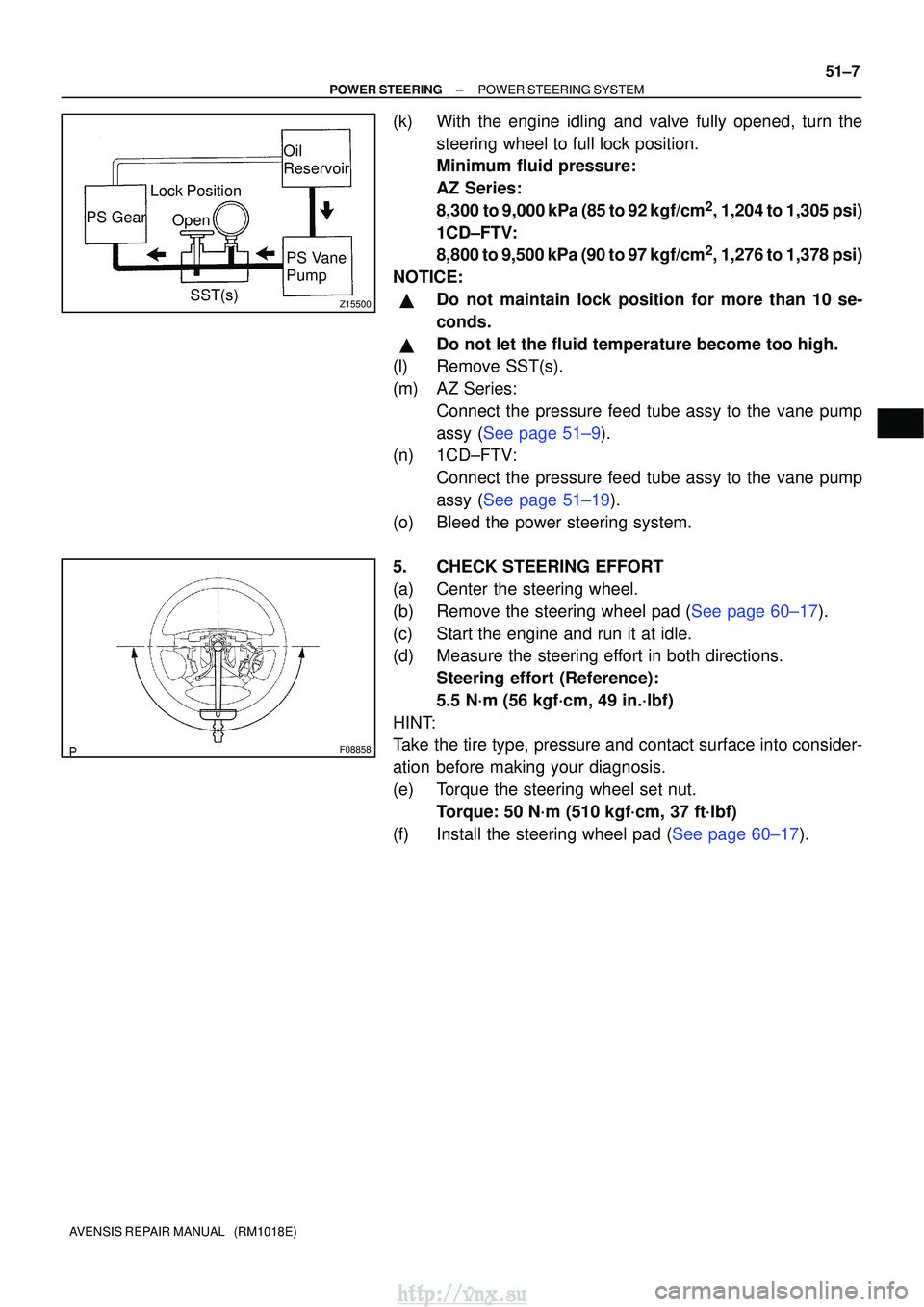
(k) With the engine idling and valve fully opened, turn the
steering wheel to full lock position.
Minimum fluid pressure:
AZ Series:
8,300 to 9,000 kPa (85 to 92 kgf/cm
2, 1,204 to 1,305 psi)
1CD±FTV:
8,800 to 9,500 kPa (90 to 97 kgf/cm
2, 1,276 to 1,378 psi)
NOTICE:
�Do not maintain lock position for more than 10 se-
conds.
�Do not let the fluid temperature become too high.
(l) Remove SST(s).
(m) AZ Series:
Connect the pressure feed tube assy to the vane pump
assy (See page 51±9).
(n) 1CD±FTV:
Connect the pressure feed tube assy to the vane pump
assy (See page 51±19).
(o) Bleed the power steering system.
5. CHECK STEERING EFFORT
(a) Center the steering wheel.
(b)Remove the steering wheel pad (See page 60±17).
(c) Start the engine and run it at idle.
(d) Measure the steering effort in both directions. Steering effort (Reference):
5.5 N´m (56 kgf´cm, 49 in.´lbf)
HINT:
Take the tire type, pressure and contact surface into consider-
ation before making your diagnosis.
(e) Torque the steering wheel set nut. Torque: 50 N´m (510 kgf´cm, 37 ft´lbf)
(f)Install the steering wheel pad (See page 60±17).
http://vnx.su
Page 1654 of 2234

71±2
±
INSTRUMENT PANEL/METERCOMBINATION METER
AVENSIS REPAIR MANUAL (RM1018E)
SLIP indicator light does not come on.
1.Wire Harness or Connector
2.Skid Control ECU
3.Combination Meter Assy±
05±752 ±
CRUISE indicator light does not come on.
1.Wire Harness or Connector
2.ECM
3.Combination Meter Assy±
±
±
High Beam indicator light does not come on.
1.Wire Harness or Connector
2.Headlight Dimmer Switch
3.Combination Meter Assy±
65±9 ±
Fr FOG indicator does not come on.
1.Wire Harness or Connector
2.Fr FOG Relay
3.Fr FOG Light Switch
4.Combination Meter Assy±
±
±
±
Rr FOG indicator does not come on.
1.Wire Harness or Connector
2.Rr FOG Relay
3.Rr FOG Light Switch
4.Combination Meter Assy±
±
±
±
TAIL indicator does not come on.
1.Wire Harness or Connector
2.TAIL Relay
3.Combination Meter Assy±
±
±
WATER LEVEL indicator does not come on (1KD±FTV).
1.Wire Harness or Connector
2.Water Level Sensor
3.Combination Meter Assy±
±
±
EMPS indicator does not come on.
1.Wire Harness or Connector
2.EMPS ECU
3.Combination Meter Assy±
±
±
A/T OIL TEMP indicator does not come on.
1.Refer to troubleshooting
2.Wire Harness or Connector
3.Combination Meter Assy05±856
±
±
ECT SNOW indicator does not come on.
1.Refer to troubleshooting
2.Wire Harness or Connector
3.Combination Meter Assy05±980±
±
AUTO LEVELING indicator does not come on.
1.Wire Harness or Connector
2.Auto Leveling ECU
3.Combination Meter Assy±
±
±
Meter Gauges:
SymptomSuspect AreaSee page
Speedometer does not operate.1.Refer to troubleshooting05±1510
Water temperature does not operate.1.Refer to troubleshooting05±1515
Tachometer does not operate.1.Refer to troubleshooting05±1513
Fuel Gauge does not operate or operates abnormally.1.Refer to troubleshooting05±1517
OTHERS:
SymptomSuspect AreaSee page
key reminder buzzer does not operate.
1. Wire Harness or Connector
2. Body ECU (KSW, DCTY)
3. Door Coutesy Switch
4. Key Unlock Warning Switch
5. Combination Meter Assy±
±
±
05±1586 ±
Light reminder buzzer does not operate.
1. Wire Harness or Connector
2. Body ECU (DCTY)
3. Combination Meter Assy±
±
±
Seat belt Warning buzzer does not operate.
1. Perform DATA LIST with hand±held tester
2. Wire Harness or Connector
3. Seat Belt Buckle Switch
4. Combination Meter Assy05±1499±
61±3
±
http://vnx.su
Page 1817 of 2234

B67164
Double±sided Tape
±
EXTERIOR/INTERIOR TRIM REAR SPOILER (WAGON MODELS)
76±31
AVENSIS REPAIR MANUAL (RM1018E)
(2) Remove the tape from the back door.
(3) Wipe off the stains with cleaner.
(b) When reusing the spoiler:
Clean the spoiler.
(1) Using a heat light, heat the spoiler.
Heating temprature: 20 ± 30 �C (68 ± 86 �F)
NOTICE:
Do not heat the spoiler excessively.
(2) Remove the tape from the spoiler.
(3) Wipe off the stains with cleaner.
(c) Install the spoiler. (1) Using a heat light, heat the door and spoiler.
Heating temperature:
Door40 ± 60� C (104 ± 140� F)
Spoiler20 ± 30�C (68 ± 86 �F)
NOTICE:
Do not heat the door and spoiler excessively.
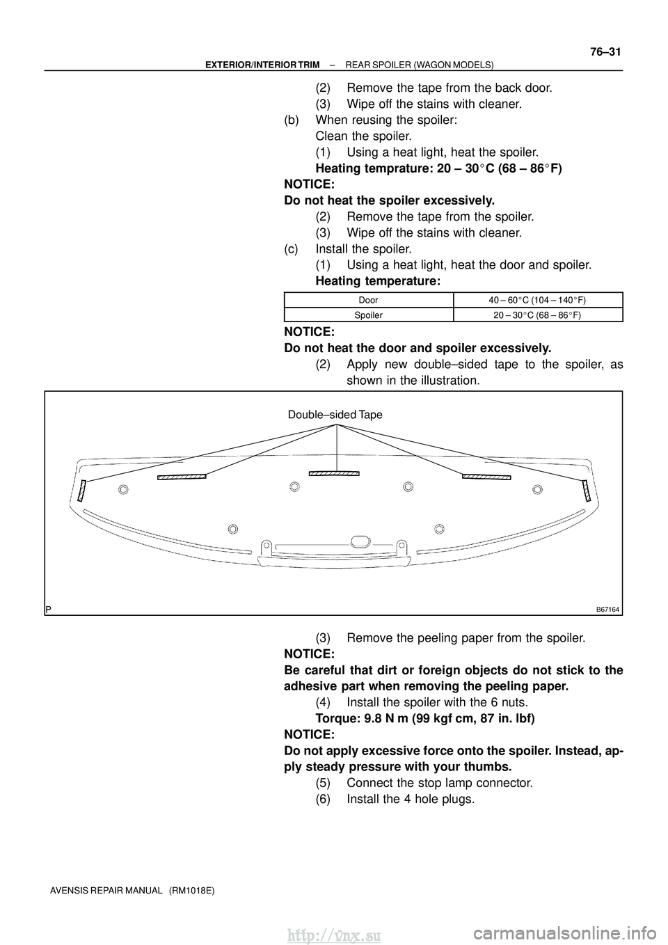
(2) Apply new double±sided tape to the spoiler, asshown in the illustration.
(3) Remove the peeling paper from the spoiler.
NOTICE:
Be careful that dirt or foreign objects do not stick to the
adhesive part when removing the peeling paper. (4) Install the spoiler with the 6 nuts.
Torque: 9.8 N �m (99 kgf �cm, 87 in. �lbf)
NOTICE:
Do not apply excessive force onto the spoiler. Instead, ap-
ply steady pressure with your thumbs. (5) Connect the stop lamp connector.
(6) Install the 4 hole plugs.
http://vnx.su
Page 1867 of 2234

AVENSIS (EWD526E)19
E
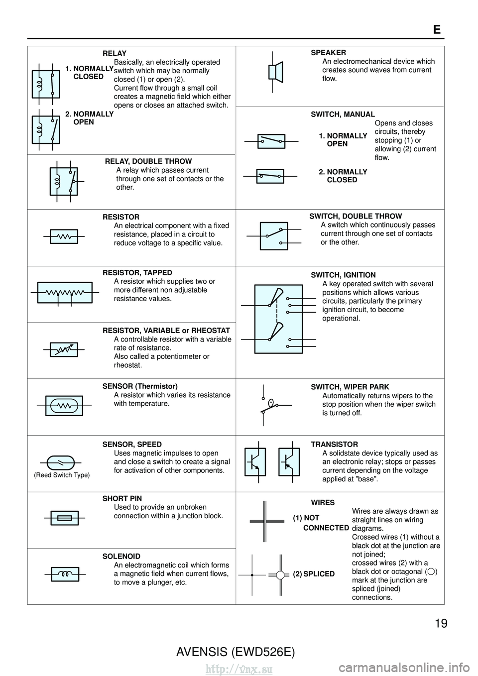
RELAY
Basically, an electrically operated
switch which may be normally
closed (1) or open (2).
Current flow through a small coil
creates a magnetic field which either
opens or closes an attached switch.
1. NORMALLY
CLOSED
2. NORMALLY
OPEN
SWITCH, MANUAL
Opens and closes
SPEAKERAn electromechanical device which
creates sound waves from current
flow.
RELAY, DOUBLE THROWA relay which passes current
through one set of contacts or the
other.
circuits, thereby
stopping (1) or
allowing (2) current
flow.1. NORMALLY
OPEN
2. NORMALLY
CLOSED
RESISTORAn electrical component with a fixed
resistance, placed in a circuit to
reduce voltage to a specific value.SWITCH, DOUBLE THROWA switch which continuously passes
current through one set of contacts
or the other.
RESISTOR, TAPPED
A resistor which supplies two or
more different non adjustable
resistance values.SWITCH, IGNITIONA key operated switch with several
positions which allows various
circuits, particularly the primary
ignition circuit, to become
operational.
RESISTOR, VARIABLE or RHEOSTAT
A controllable resistor with a variable
rate of resistance.
Also called a potentiometer or
rheostat.
SENSOR (Thermistor)A resistor which varies its resistance
with temperature.SWITCH, WIPER PARKAutomatically returns wipers to the
stop position when the wiper switch
is turned off.
(Reed Switch Type)
SENSOR, SPEEDUses magnetic impulses to open
and close a switch to create a signal
for activation of other components.TRANSISTORA solidstate device typically used as
an electronic relay; stops or passes
current depending on the voltage
applied at ”base”.
SHORT PINUsed to provide an unbroken
connection within a junction block.WIRES Wires are always drawn as
straight lines on wiring
diagrams.
Crossed wires (1) without a
black dot at the junction are
(1) NOT
CONNECTED
SOLENOID
An electromagnetic coil which forms
a magnetic field when current flows,
to move a plunger, etc.
black dot at the junction are
not joined;
crossed wires (2) with a
black dot or octagonal ( )
mark at the junction are
spliced (joined)
connections.
(2) SPLICED
http://vnx.su