Page 366 of 2234

AVENSIS REPAIR MANUAL (RM1018E)
FUEL SYSTEM(1AZ±FSE)
PRECAUTION
1.PRECAUTION
(a)Before working o")
110UZ±01
A75339
Fuel
Pump
Connector
B00679
Vinyl or Plastic Bag
11±30
±
FUELFUEL SYSTEM(1AZ±FSE)
AVENSIS REPAIR MANUAL (RM1018E)
FUEL SYSTEM(1AZ±FSE)
PRECAUTION
1.PRECAUTION
(a)Before working on fuel system, disconnect negative (±) battery cable.
(b)Do not smoke or work near fire when handling the fuel system.
(c)Keep gasoline away from rubber or leather parts. 2.DISCHARGE FUEL SYSTEM PRESSURE
CAUTION:
�Do not disconnect any part of the fuel system until
you have discharged the fuel system pressure.
�Even after discharging the fuel pressure, place a
shop rag over fittings as you separate them to reduce
risk of fuel spray on yourself or in the engine compart-
ment.
(a)Disconnect the fuel pump connector.
(b)Start the engine. After the engine has stopped, turn the ignition switch OFF.
(c)Disconnect the negative (±) battery cable.
(d)Connect the fuel pump connector.
3.FUEL SYSTEM
(a)When disconnecting the high fuel pressure line, a large amount of gasoline will spill out, so observe these proce-
dures.
(1)Discharge the pressure in the fuel system. (See step 2)
(2) Disconnect the fuel pump tube. (See page 11±93)
(3) Drain the fuel that remained inside the fuel pump
tube.
(4) Cover the disconnected fuel pump tubes with a vinyl or a plastic bag to prevent damage and dirt.
(5) Place a tray under the vehicle or point of disconnec- tion to catch any fuel that may spill.
http://vnx.su
Page 383 of 2234

(d)
(c)
±
FUELFUEL TANK ASSY(GASOLINE)
11±93
AVENSIS REPAIR MANUAL (RM1018E)
Removal & Installation and Disassembly & Reassembly
1.DISCHA")
110U5±01
A78493
A80060
w/o HID Sensor:
w/ HID Sensor:
(c)
(d)
(c)
±
FUELFUEL TANK ASSY(GASOLINE)
11±93
AVENSIS REPAIR MANUAL (RM1018E)
Removal & Installation and Disassembly & Reassembly
1.DISCHARGE FUEL SYSTEM PRESSURE
HINT:
�1ZZ±FE/3ZZ±FE: 11±1
�1AZ±FE: 11±15
�1AZ±FSE: 11±30
2.REMOVE REAR SEAT CUSHION ASSY (SEAT FIXED TYPE) (See page 72±32)
3.REMOVE COVER, RR FLOOR SERVICE HOLE (See page 11±85)
4.DISCONNECT FUEL TANK RETURN TUBE (1AZ±FSE ENGINE TYPE)
(See page 11±85)
5.DISCONNECT FUEL TANK MAIN TUBE SUB±ASSY (See page 11±85)
6.DISCONNECT FUEL EVAPORATION TUBE SUB±ASSY NO.2 (See page 11±85)
7.REMOVE FUEL SUCTION W/PUMP & GAGE TUBE ASSY (See page 11±85)
SST 09808±14010
8. DRAIN FUEL
9. REMOVE FRONT FLOOR FOOTREST (W/O HID SENSOR)
10.REMOVE FLOOR PANEL BRACE FRONT (See page 15±2)
11. REMOVE EXHAUST PIPE ASSY CENTER(1ZZ±FE/3ZZ±FE ENGINE TYPE)
(a) Using a clip remover, remove the 2 clips. (w/o HID Sensor)
(b) Open the floor carpet. (w/o HID Sensor)
(c) Disconnect the heated oxygen sensor connector.
(d) Remove the grommet. (w/o HID Sensor)
http://vnx.su
Page 406 of 2234
")
A80119
New Gasket
Hollow
Screw
Union
BoltSST
Nozzle Leakage
No. 2 Pipe
New Gasket
SST
A79146
Check
Valve
Nozzle Leakage
No. 2 Pipe
New Gasket
A09663
:Seal Packing
±
FUEL INJECTOR ASSY (1CD±FTV)
11±63
AVENSIS REPAIR MANUAL (RM1018E)
(2) Install the bolt, the nozzle leakage No. 2 pipe and
the gasket to the cylinder head with SST.
SST 09280±00010
Torque:
8.8 N �m (90 kgf �cm, 79 in. �lbf) for bolt
21 N� m (214 kgf� cm, 15 ft�lbf) for SST
(3) Apply a light coat of soapy water (any fluid to detect
fuel leakage) on the nozzle leakage pipe No. 2 con-
nection.
(4) Using SST (turbocharger pressure gauge), attach SST to the fuel return side of the nozzle leakage No.
2 pipe, and maintain 100 kPa (1.0 kgf/cm
2, 14.5 psi)
of pressure for 60 seconds to check that there are
no bubbles from the pipe connection.
SST 09992±00242
(5) After checking fuel leaks, wipe off soapy water from
the pipe connection.
(6) Remove 2 SSTs, and then remove the bolt, the nozzle leakage No.2 pipe and the gasket.
(7) Place a new gasket and reinstall the nozzle leakage No. 2 pipe with the check valve and the bolt.
Torque:
8.8 N� m (90 kgf �cm, 79 in. �lbf) for bolt
21 N� m (214 kgf� cm, 15 ft�lbf) for check valve
HINT:
Do not disassemble the check valve on the engine. (8) Reconnect the fuel hose to the nozzle leakage No.
2 pipe.
19. INSTALL CYLINDER HEAD COVER SUB±ASSY
(a) Remove any old packing (FIPG) material.
(b) Apply seal packing to the cylinder head. Seal packing: Part No. 08826±00080 or equivalent
(c) Install the gasket to the cylinder head cover.
(d) Install the cylinder head cover with the 10 bolts. Torque: 13 N �m (135 kgf� cm, 9.7 ft�lbf)
http://vnx.su
Page 408 of 2234

11±65
AVENSIS REPAIR MANUAL (RM1018E)
23.INSTALL INJECTION PIPE SUB±ASSY NO.2
SST09023±12700
HINT:
Perform the same procedures as injection pipe No. 1.
24.INSTALL I")
±
FUELINJECTOR ASSY(1CD±FTV)
11±65
AVENSIS REPAIR MANUAL (RM1018E)
23.INSTALL INJECTION PIPE SUB±ASSY NO.2
SST09023±12700
HINT:
Perform the same procedures as injection pipe No. 1.
24.INSTALL INJECTION PIPE SUB±ASSY NO.3
SST09023±12700
HINT:
Perform the same procedures as injection pipe No. 1.
25.INSTALL INJECTION PIPE SUB±ASSY NO.4
SST09023±12700
HINT:
Perform the same procedures as injection pipe No. 1.
26.INSTALL AIR TUBE NO.1 (See page 14±270)
27. INSTALL AIR CLEANER ASSY Torque: 7.0 N �m (71 kgf �cm, 62 in. �lbf)
28. INSTALL ENGINE COVER NO.1
Torque: 8.0 N �m (82 kgf �cm, 71 in. �lbf)
29. INSTALL VACUUM RESERVOIR SUB±ASSY Torque: 8.3 N �m (85 kgf �cm, 74 in. �lbf)
30. CHECK FOR FUEL LEAKS
NOTICE:
Under ACTIVE TEST mode, fuel pressure increases. Take precautions to prevent fuel from spraying
on you or inside the engine compartment.
HINT:
During ACTIVE TEST mode, engine speed goes high and combustion noise bec\
omes loud.
(a) Check that there are no fuel leaks from any part of the fuel system at t\
he engine stops.
HINT:
If fuel leakage could be found on specific parts, replace them with new \
parts.
(b) While cranking or when starting the engine, check that there is no leaks from\
any part of the fuel sys-
tem.
HINT:
If fuel leakage could be found on specific parts, replace them with new pa\
rts.
(c) Disconnect the fuel hose from the common rail.
(d) While cranking the engine, check fuel leaks from the return pipe.
HINT:
If there is fuel leakage, replace the common rail.
(e) Connect the hand±held tester to the DLC3.
(f) Start the engine and push the hand±held tester main switch ON.
(g) Select the FUEL LEAK test of ACTIVE TEST mode on the hand±held tester\
.
(h) If you do not have the hand±held tester, depress the accelerator pedal quickly and fully to increase the engine speed at maximum and keep it for 2 seconds. Repeat this opera\
tion several times.
(i) Check that there are no leaks from any part of the fuel system.
NOTICE:
If the leakage from the return pipe is less than 10 cc (0.6 cu in.) in\
a minute, it is acceptable.
HINT:
If fuel leakage could be found on specific parts, replace them with new \
parts.
(j) Reconnect the fuel hose to the common rail.
http://vnx.su
Page 458 of 2234
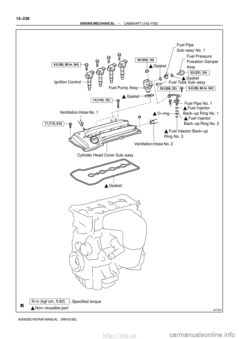
A77374
N´m (kgf´cm, ft´lbf): Specified torque
� Non±reusable part �
Gasket
Cylinder Head Cover Sub±assy
11 (115, 8.0)
Ventilation Hose No. 1 �
Gasket
Fuel Tube Sub±assy �
Gasket
Fuel Pipe
Sub±assy No. 1
Fuel Pressure
Pulsation Damper
Assy
Fuel Pump Assy
� Gasket14 (143, 10)
Ignition Control
9.0 (90, 80 in. �lbf)
9.0 (90, 80 in. �lbf)
� O±ring
Ventilation Hose No. 2
33 (331, 24)
25 (255, 18)
Fuel Pipe No. 1
� Fuel Injector
Back±up Ring No. 1
� Fuel Injector Back±up
Ring No. 3 �
Fuel Injector
Back±up Ring No. 2
30 (306, 22)
14±238
±
ENGINE MECHANICAL CAMSHAFT (1AZ±FSE)
AVENSIS REPAIR MANUAL (RM1018E)
http://vnx.su
Page 460 of 2234
141BQ±01
A77339
A77284
14±240
±
ENGINE MECHANICALCAMSHAFT(1AZ±FSE)
AVENSIS REPAIR MANUAL (RM1018E)
REPLACEMENT
1.DISCHARGE FUEL SYSTEM PRESSURE (See page 11±30)
2.REMOVE RADIATOR SUPPORT OPENING COVER
3.REMOVE ENGINE ROOM COVER SIDE
4.REMOVE ENGINE UNDER COVER RH 5.REMOVE ENGINE COVER SUB±ASSY NO.1
(a)Remove the 2 nuts and the engine cover No. 1.
6.REMOVE IGNITION COIL ASSY
(a)Remove the 4 bolts and the ignition coils.
7.REMOVE FUEL PRESSURE PULSATION DAMPER ASSY
8.REMOVE FUEL TUBE SUB±ASSY (See page 11±33)
9.REMOVE FUEL PIPE SUB±ASSY NO.1 (See page 11±52) SST 09023±12900
10.REMOVE FUEL PUMP ASSY (See page 11±52)
11.REMOVE CYLINDER HEAD COVER SUB±ASSY (See page 14±222)
12. SET NO. 1 CYLINDER TO TDC/COMPRESSION
(a) Turn the crankshaft pulley, and align its groove with timingmark 0 of the timing chain cover.
http://vnx.su
Page 465 of 2234

14±245
AVENSIS REPAIR MANUAL (RM1018E)
(b)Install a new gasket chain tensioner No.")
A77395
Engine
Front
A77396
HookPinTurn
Disconnect
A77397
Push Turn
Plunger
±
ENGINE MECHANICALCAMSHAFT(1AZ±FSE)
14±245
AVENSIS REPAIR MANUAL (RM1018E)
(b)Install a new gasket chain tensioner No. 1 with 2 nuts.
Torque: 9.0 N �m (92 kgf�cm,80 in. �lbf)
NOTICE:
If the hook is disengaged while installing, apply the hook
again, and then resume the installation.
(c)Turn the crankshaft counterclockwise, and check that the
pin is disengaged from the hook.
(d)Turn the crankshaft clockwise, and check the plunger is extended.
21.INSTALL CYLINDER HEAD COVER SUB±ASSY (See page 14±222)
22.INSTALL FUEL PUMP ASSY (See page 11±52)
23.INSTALL FUEL PIPE SUB±ASSY NO.1 (See page 11±52) SST 09023±12900
24.INSTALL FUEL TUBE SUB±ASSY (See page 11±30)
25.INSTALL FUEL PRESSURE PULSATION DAMPER ASSY (See page 11±52)
26. INSTALL IGNITION COIL ASSY Torque: 9.0 N �m (92 kgf �cm, 80 in. �lbf)
27. CHECK FOR ENGINE OIL LEAKS
28. INSTALL ENGINE COVER SUB±ASSY NO.1 Torque: 7.0 N �m (71 kgf �cm, 62 in. �lbf)
http://vnx.su
Page 528 of 2234
A77374
N´m (kgf´cm, ft´lbf): Specified torque
� Non±reusable part �
Gasket
Cylinder Head Cover Sub±assy
11 (115, 8.0)
Ventilation Hose No. 1 �
Gasket
Fuel Tube Sub±assy �
Gasket
Fuel Pipe
Sub±assy No. 1
Fuel Pressure
Pulsation Damper
Assy
Fuel Pump Assy
� Gasket14 (143, 10)
Ignition Control
9.0 (90, 80 in. �lbf)
9.0 (90, 80 in. �lbf)
� O±ring
Ventilation Hose No. 2
33 (331, 24)
25 (255, 18)
Fuel Pipe No. 1
� Fuel Injector
Back±up Ring No. 1
� Fuel Injector Back±up
Ring No. 3 �
Fuel Injector
Back±up Ring No. 2
30 (306, 22)
14±220
±
ENGINE MECHANICAL CHAIN SUB±ASSY (1AZ±FSE)
AVENSIS REPAIR MANUAL (RM1018E)
http://vnx.su

AVENSIS REPAIR MANUAL (RM1018E)
REPLACEMENT
1.DISCHARGE FUEL SYSTEM PRESSURE (See page 11±30)
2.REMOVE RADIATOR SUPPORT OPENIN")
