Page 1018 of 2234
270E4±01
G23906
G25775
G23871
������G25777
27±24
±
REAR SUSPENSION LOWER CONTROL ARM ASSY LH
AVENSIS REPAIR MANUAL (RM1018E)
LOWER CONTROL ARM ASSY LH
REPLACEMENT
HINT:
COMPONENTS: See page 27±2.
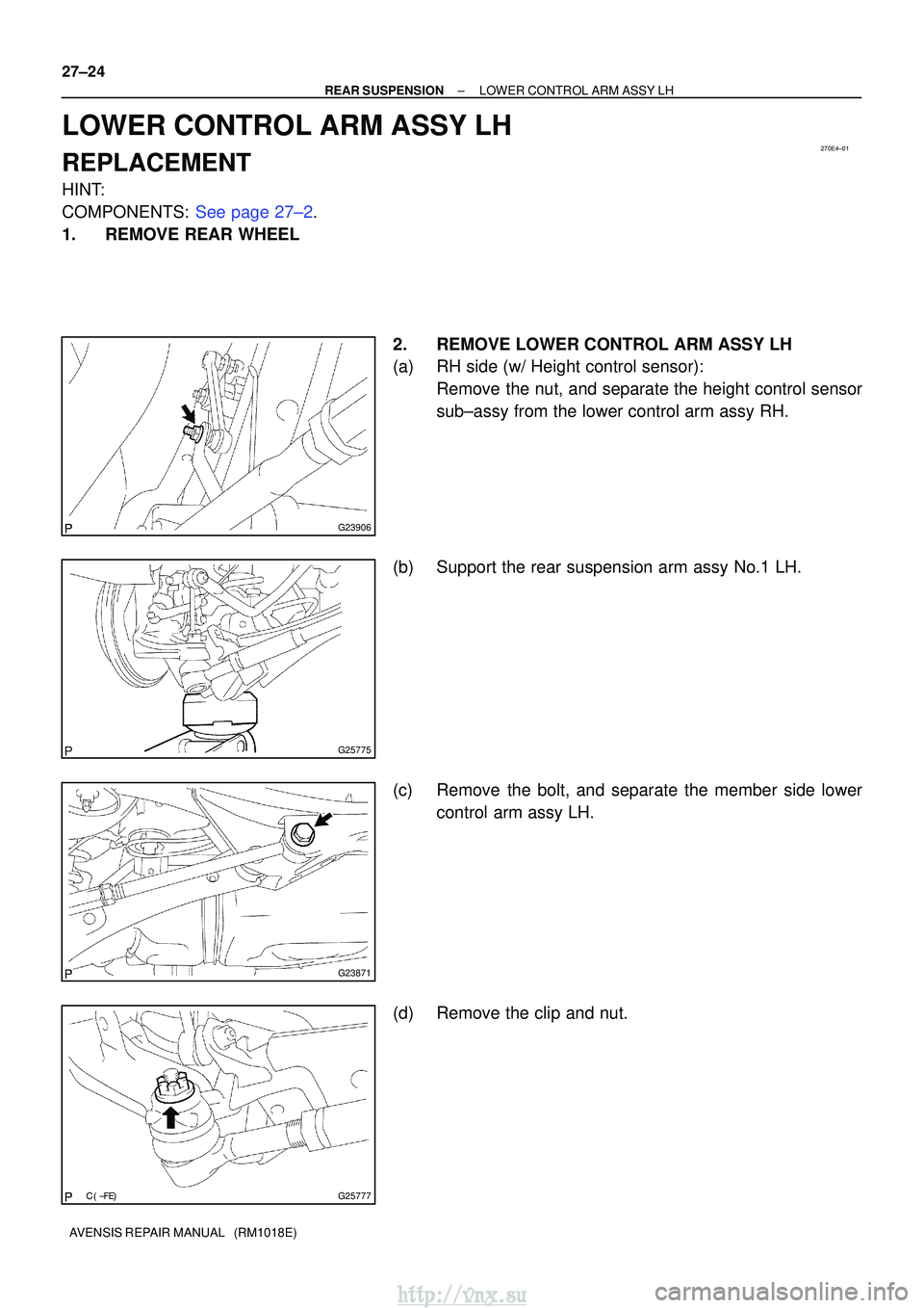
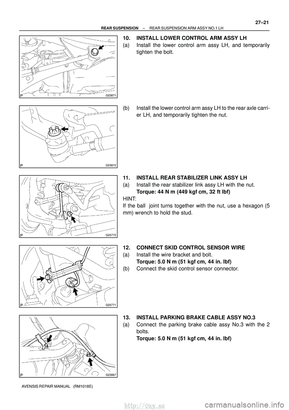
1. REMOVE REAR WHEEL 2. REMOVE LOWER CONTROL ARM ASSY LH
(a) RH side (w/ Height control sensor):Remove the nut, and separate the height control sensor
sub±assy from the lower control arm assy RH.
(b) Support the rear suspension arm assy No.1 LH.
(c) Remove the bolt, and separate the member side lower control arm assy LH.
(d) Remove the clip and nut.
http://vnx.su
Page 1019 of 2234
������G23882
SST
G22395
G23871
������G25777
±
REAR SUSPENSION LOWER CONTROL ARM ASSY LH
27±25
AVENSIS REPAIR MANUAL (RM1018E)
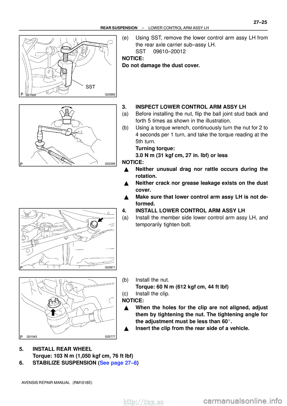
(e) Using SST, remove the lower control arm assy LH from
the rear axle carrier sub±assy LH.
SST 09610±20012
NOTICE:
Do not damage the dust cover.
3. INSPECT LOWER CONTROL ARM ASSY LH
(a) Before installing the nut, flip the ball joint stud back and forth 5 times as shown in the illustration.
(b) Using a torque wrench, continuously turn the nut for 2 to 4 seconds per 1 turn, and take the torque reading at the
5th turn.
Turning torque:
3.0 N� m (31 kgf �cm, 27 in. �lbf) or less
NOTICE:
�Neither unusual drag nor rattle occurs during the
rotation.
�Neither crack nor grease leakage exists on the dust
cover.
�Make sure that lower control arm assy LH is not de-
formed.
4. INSTALL LOWER CONTROL ARM ASSY LH
(a) Install the member side lower control arm assy LH, and temporarily tighten bolt.
(b) Install the nut. Torque: 60 N �m (612 kgf� cm, 44 ft�lbf)
(c) Install the clip.
NOTICE:
�When the holes for the clip are not aligned, adjust
them by tightening the nut. The tightening angle for
the adjustment must be less than 60� .
�Insert the clip from the rear side of a vehicle.
5. INSTALL REAR WHEEL Torque: 103 N� m (1,050 kgf�cm, 76 ft �lbf)
6.STABILIZE SUSPENSION (See page 27±8)
http://vnx.su
Page 1020 of 2234
G23871
G23906
27±26
±
REAR SUSPENSION LOWER CONTROL ARM ASSY LH
AVENSIS REPAIR MANUAL (RM1018E)
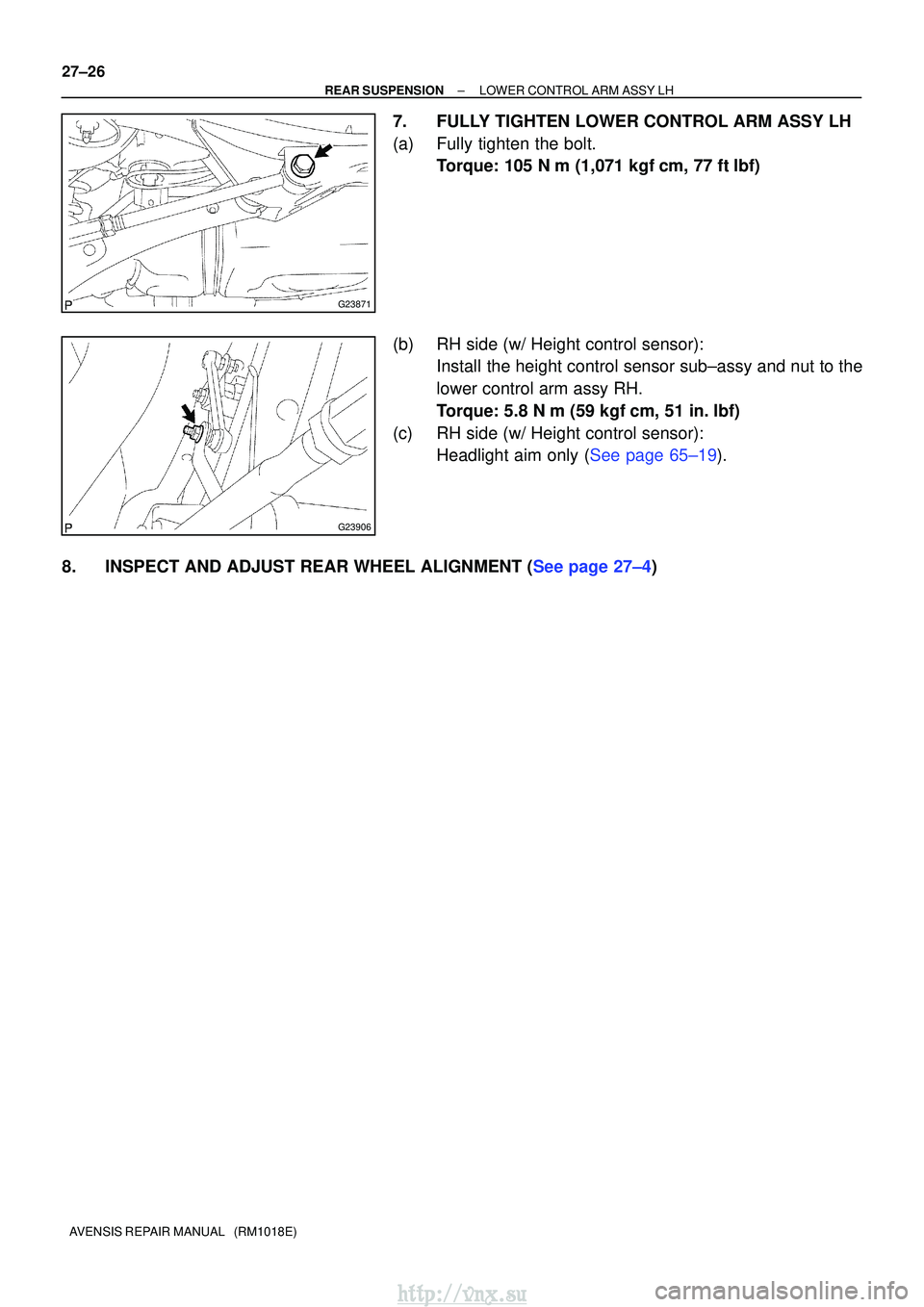
7. FULLY TIGHTEN LOWER CONTROL ARM ASSY LH
(a) Fully tighten the bolt. Torque: 105 N� m (1,071 kgf�cm, 77 ft �lbf)
(b) RH side (w/ Height control sensor): Install the height control sensor sub±assy and nut to the
lower control arm assy RH.
Torque: 5.8 N �m (59 kgf �cm, 51 in. �lbf)
(c) RH side (w/ Height control sensor): Headlight aim only (See page 65±19).
8.INSPECT AND ADJUST REAR WHEEL ALIGNMENT (See page 27±4)
http://vnx.su
Page 1025 of 2234
G23868
G23867
G25772
G25771
27±12
±
REAR SUSPENSION REAR SHOCK ABSORBER WITH COIL SPRING
AVENSIS REPAIR MANUAL (RM1018E)
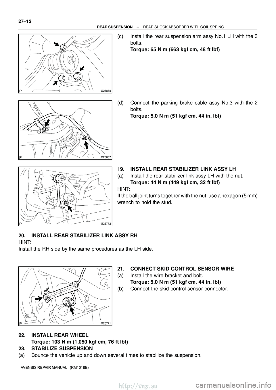
(c) Install the rear suspension arm assy No.1 LH with the 3 bolts.
Torque: 65 N �m (663 kgf� cm, 48 ft�lbf)
(d) Connect the parking brake cable assy No.3 with the 2 bolts.
Torque: 5.0 N� m (51 kgf�cm, 44 in. �lbf)
19. INSTALL REAR STABILIZER LINK ASSY LH
(a) Install the rear stabilizer link assy LH with the nut. Torque: 44 N �m (449 kgf� cm, 32 ft�lbf)
HINT:
If the ball joint turns together with the nut, use a hexagon (5 mm)
wrench to hold the stud.
20. INSTALL REAR STABILIZER LINK ASSY RH
HINT:
Install the RH side by the same procedures as the LH side. 21. CONNECT SKID CONTROL SENSOR WIRE
(a) Install the wire bracket and bolt.Torque: 5.0 N �m (51 kgf �cm, 44 in. �lbf)
(b) Connect the skid control sensor connector.
22. INSTALL REAR WHEEL Torque: 103 N� m (1,050 kgf�cm, 76 ft �lbf)
23. STABILIZE SUSPENSION
(a) Bounce the vehicle up and down several times to stabilize the suspension\
.
http://vnx.su
Page 1028 of 2234
270E0±01
������G26285
w/ Height Control Sensor:
5.8 (59, 51 in.�lbf)
80 (816, 59)
Rear Suspension Member Sub±assy
Rear Shock Absorber
Cushion Washer No.1
Coil Rear Spring
Rear Coil Spring Insulator Upper LH
Rear Spring Bumper No.1 LH
Rear Suspension Support Assy LH
Rear Spring Front Bracket
Sub±assy LH
Rear Shock
Absorber Cushion No.1
Lower Control Arm Assy RH
Rear Shock Absorber
Assy LH
160 (1,632, 118)
110 (1,122, 81)
65 (663, 48)
Rear Suspension
Support Stopper
Rear Suspension Arm
Bracket Assy LH
Rear Suspension
Arm Bush No.1� Camber Adjust Cam Assy
Rear Suspension Arm Assy No.1 LH
74 (755, 55)
105 (1,071, 77)
44 (449, 32)
74 (755, 55)
74 (755, 55)
Parking Brake Cable Assy No.3
5.0 (51, 44 in.� lbf)Rear Axle Carrier Sub±assy LH
Skid Control Sensor Wire
74 (755, 55)
Upper Control Arm Assy
Camber Adjust Cam No.2
Lower Control Arm Assy LH
105 (1,071, 77)
5.0 (51, 44 in.�lbf)
60 (612, 44)
N �m (kgf� cm, ft�lbf) : Specified torque
Non±reusable part
�
56 (571, 41)
�56 (571, 41)
Clip
Clip
27±2
±
REAR SUSPENSION REAR SUSPENSION
AVENSIS REPAIR MANUAL (RM1018E)
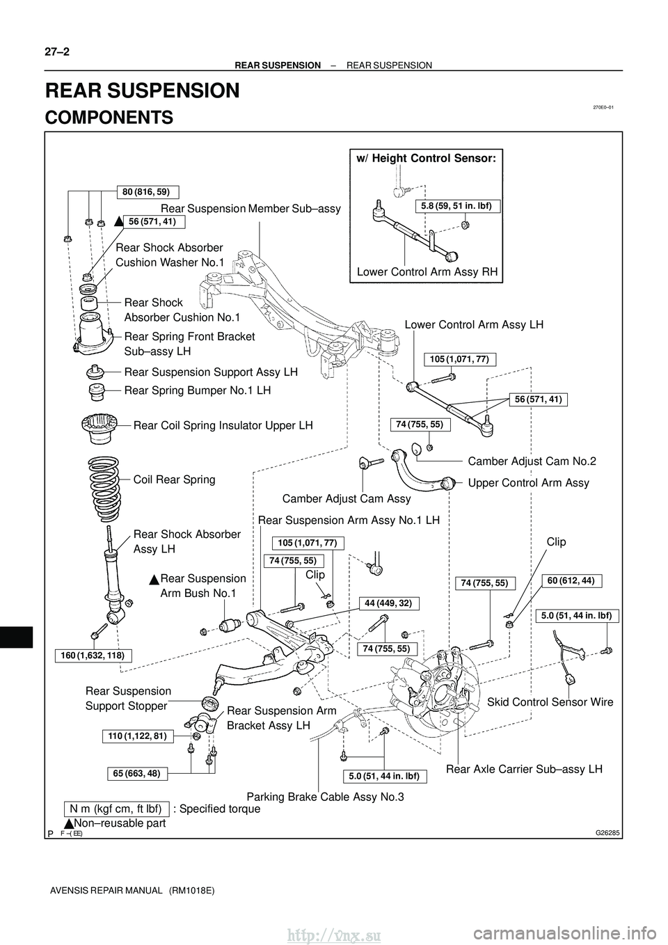
REAR SUSPENSION
COMPONENTS
http://vnx.su
Page 1030 of 2234
270E3±01
G23867
G25771
G25772
G25775
±
REAR SUSPENSION REAR SUSPENSION ARM ASSY NO.1 LH
27±15
AVENSIS REPAIR MANUAL (RM1018E)
REAR SUSPENSION ARM ASSY NO.1 LH
OVERHAUL
HINT:
COMPONENTS: See page 27±2.
1. REMOVE REAR WHEEL
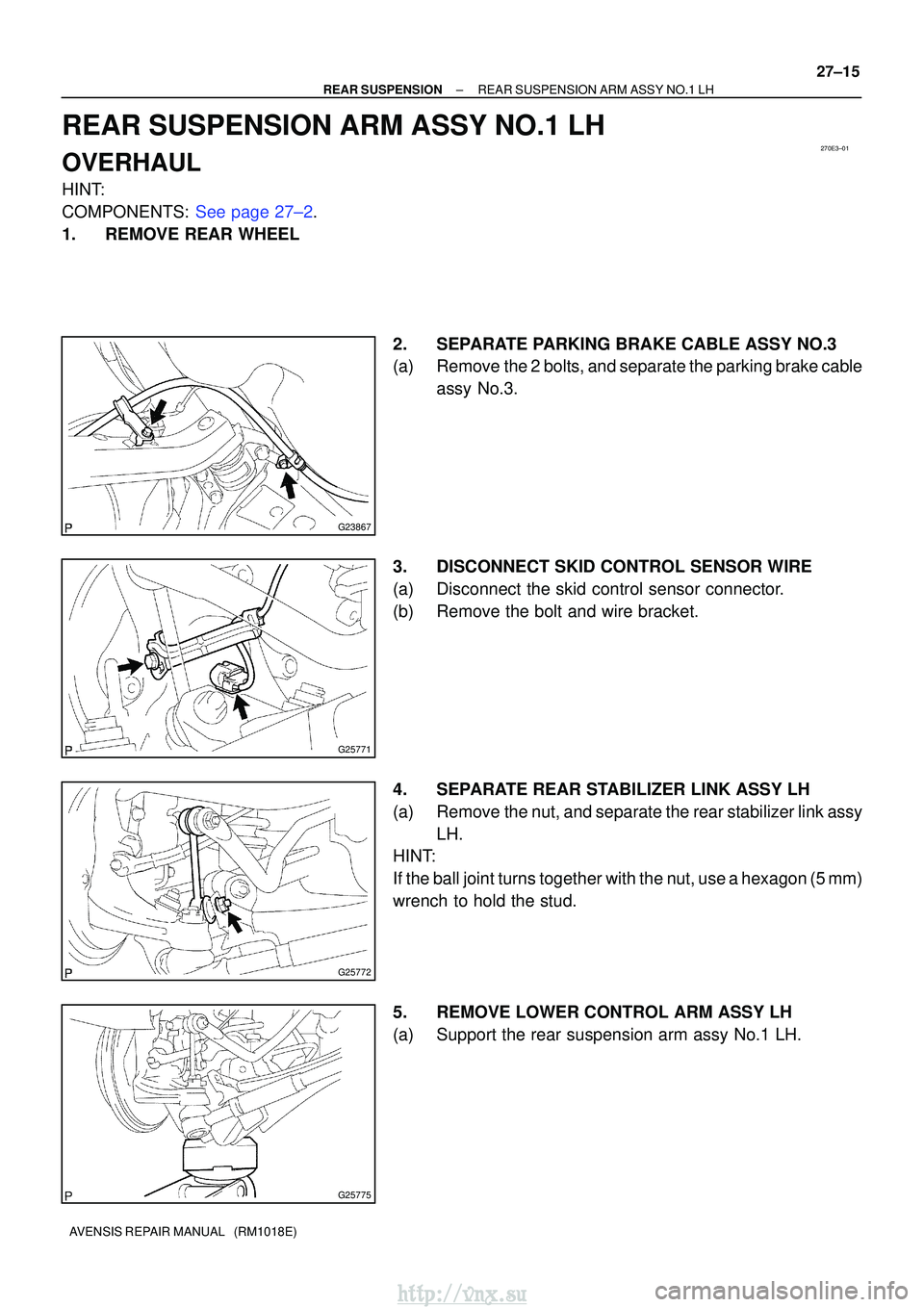
2. SEPARATE PARKING BRAKE CABLE ASSY NO.3
(a) Remove the 2 bolts, and separate the parking brake cableassy No.3.
3. DISCONNECT SKID CONTROL SENSOR WIRE
(a) Disconnect the skid control sensor connector.
(b) Remove the bolt and wire bracket.
4. SEPARATE REAR STABILIZER LINK ASSY LH
(a) Remove the nut, and separate the rear stabilizer link assy LH.
HINT:
If the ball joint turns together with the nut, use a hexagon (5 mm)
wrench to hold the stud.
5. REMOVE LOWER CONTROL ARM ASSY LH
(a) Support the rear suspension arm assy No.1 LH.
http://vnx.su
Page 1031 of 2234
G23871
G23872
G23873
SST
G23880
������G23883
SST
27±16
±
REAR SUSPENSION REAR SUSPENSION ARM ASSY NO.1 LH
AVENSIS REPAIR MANUAL (RM1018E)
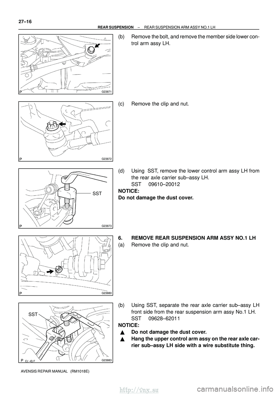
(b) Remove the bolt, and remove the member side lower con- trol arm assy LH.
(c) Remove the clip and nut.
(d) Using SST, remove the lower control arm assy LH from the rear axle carrier sub±assy LH.
SST 09610±20012
NOTICE:
Do not damage the dust cover.
6. REMOVE REAR SUSPENSION ARM ASSY NO.1 LH
(a) Remove the clip and nut.
(b) Using SST, separate the rear axle carrier sub±assy LH front side from the rear suspension arm assy No.1 LH.
SST 09628±62011
NOTICE:
�Do not damage the dust cover.
�Hang the upper control arm assy on the rear axle car-
rier sub±assy LH side with a wire substitute thing.
http://vnx.su
Page 1036 of 2234
G23871
G23872
G25772
G25771
G23867
±
REAR SUSPENSION REAR SUSPENSION ARM ASSY NO.1 LH
27±21
AVENSIS REPAIR MANUAL (RM1018E)
10. INSTALL LOWER CONTROL ARM ASSY LH
(a) Install the lower control arm assy LH, and temporarily
tighten the bolt.
(b) Install the lower control arm assy LH to the rear axle carri- er LH, and temporarily tighten the nut.
11. INSTALL REAR STABILIZER LINK ASSY LH
(a) Install the rear stabilizer link assy LH with the nut. Torque: 44 N �m (449 kgf� cm, 32 ft�lbf)
HINT:
If the ball joint turns together with the nut, use a hexagon (5
mm) wrench to hold the stud.
12. CONNECT SKID CONTROL SENSOR WIRE
(a) Install the wire bracket and bolt. Torque: 5.0 N �m (51 kgf �cm, 44 in. �lbf)
(b) Connect the skid control sensor connector.
13. INSTALL PARKING BRAKE CABLE ASSY NO.3
(a) Connect the parking brake cable assy No.3 with the 2 bolts.
Torque: 5.0 N� m (51 kgf�cm, 44 in. �lbf)
http://vnx.su