Page 495 of 2234
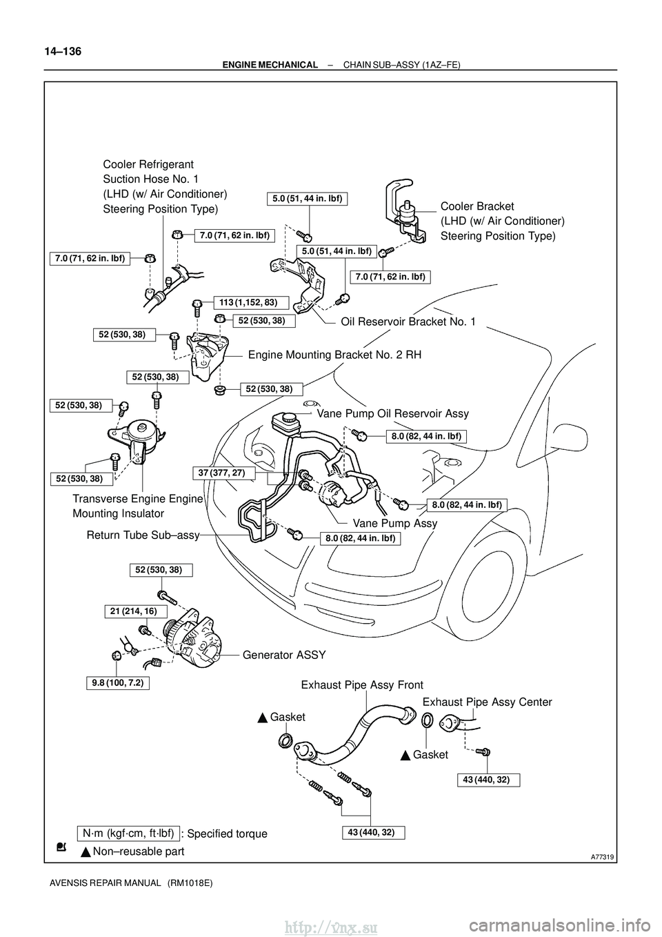
A77319
N´m (kgf´cm, ft´lbf): Specified torque
� Non±reusable part �
Gasket
Cooler Bracket
(LHD (w/ Air Conditioner)
Steering Position Type)
113 (1,152, 83)
Cooler Refrigerant
Suction Hose No. 1
(LHD (w/ Air Conditioner)
Steering Position Type)
8.0 (82, 44 in. �lbf)
8.0 (82, 44 in. �lbf)
8.0 (82, 44 in. �lbf)
52 (530, 38)
Transverse Engine Engine
Mounting Insulator
Vane Pump Oil Reservoir Assy
Return Tube Sub±assy
52 (530, 38)
21 (214, 16)
9.8 (100, 7.2)
Generator ASSY
Exhaust Pipe Assy Front
43 (440, 32)
� Gasket
43 (440, 32)
7.0 (71, 62 in. �lbf)
52 (530, 38)
7.0 (71, 62 in. �lbf)
Oil Reservoir Bracket No. 1
52 (530, 38)
52 (530, 38)
Engine Mounting Bracket No. 2 RH
7.0 (71, 62 in. �lbf)
5.0 (51, 44 in. �lbf)
5.0 (51, 44 in. �lbf)
52 (530, 38)
Exhaust Pipe Assy Center
52 (530, 38)
Vane Pump Assy
37 (377, 27)
14±136
±
ENGINE MECHANICAL CHAIN SUB±ASSY (1AZ±FE)
AVENSIS REPAIR MANUAL (RM1018E)
http://vnx.su
Page 497 of 2234
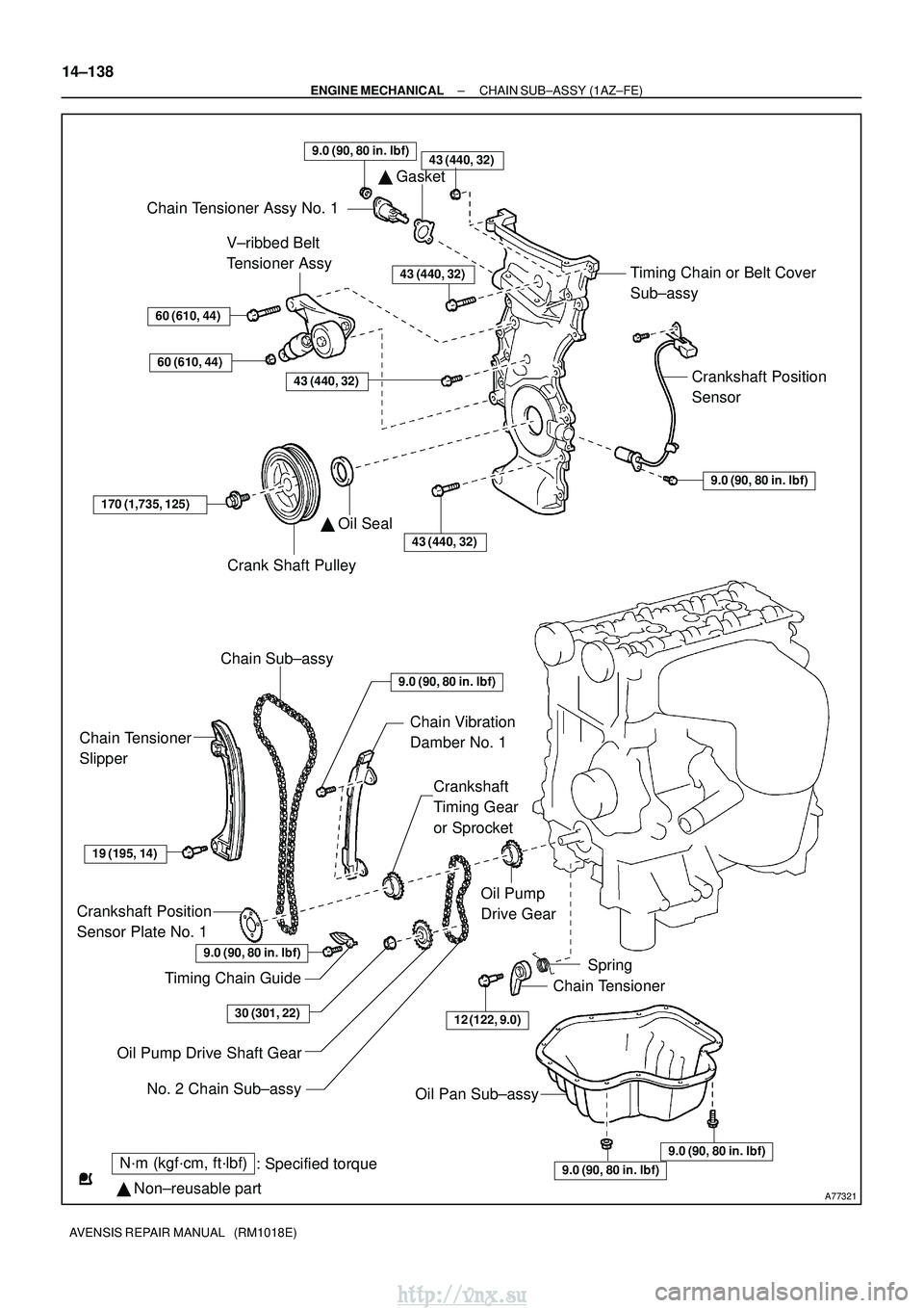
A77321
N´m (kgf´cm, ft´lbf): Specified torque
� Non±reusable part
43 (440, 32)
� Gasket
Chain Tensioner Assy No. 1
Timing Chain or Belt Cover
Sub±assy
Crankshaft Position
Sensor
9.0 (90, 80 in. �lbf)
V±ribbed Belt
Tensioner Assy
60 (610, 44)
60 (610, 44)
43 (440, 32)
43 (440, 32)
170 (1,735, 125)
Crank Shaft Pulley
� Oil Seal
43 (440, 32)
Chain Sub±assy
Chain Tensioner
Slipper
Chain Vibration
Damber No. 1
Crankshaft
Timing Gear
or Sprocket
19 (195, 14)
Crankshaft Position
Sensor Plate No. 1
Timing Chain Guide
Oil Pump
Drive Gear
12 (122, 9.0)
Spring
Chain Tensioner
Oil Pump Drive Shaft Gear
Oil Pan Sub±assy
9.0 (90, 80 in. �lbf)
9.0 (90, 80 in. �lbf)
9.0 (90, 80 in. �lbf)
30 (301, 22)
No. 2 Chain Sub±assy
9.0 (90, 80 in. �lbf)
9.0 (90, 80 in. �lbf)
14±138
±
ENGINE MECHANICAL CHAIN SUB±ASSY (1AZ±FE)
AVENSIS REPAIR MANUAL (RM1018E)
http://vnx.su
Page 498 of 2234
141B8±01
A77281
A77292
A77299
±
ENGINE MECHANICALCHAIN SUB±ASSY(1AZ±FE)
14±139
AVENSIS REPAIR MANUAL (RM1018E)
REPLACEMENT
1.REMOVE FRONT WHEEL RH
2.REMOVE RADIATOR SUPPORT OPENING COVER
3.REMOVE ENGINE ROOM COVER SIDE
4.REMOVE ENGINE UNDER COVER RH
5.REMOVE ENGINE UNDER COVER LH
6.DRAIN ENGINE OIL
(a)Install a new gasket and the drain plug after draining the engine oil.
Torque: 25 N �m (255 kgf�cm,18 ft�lbf)
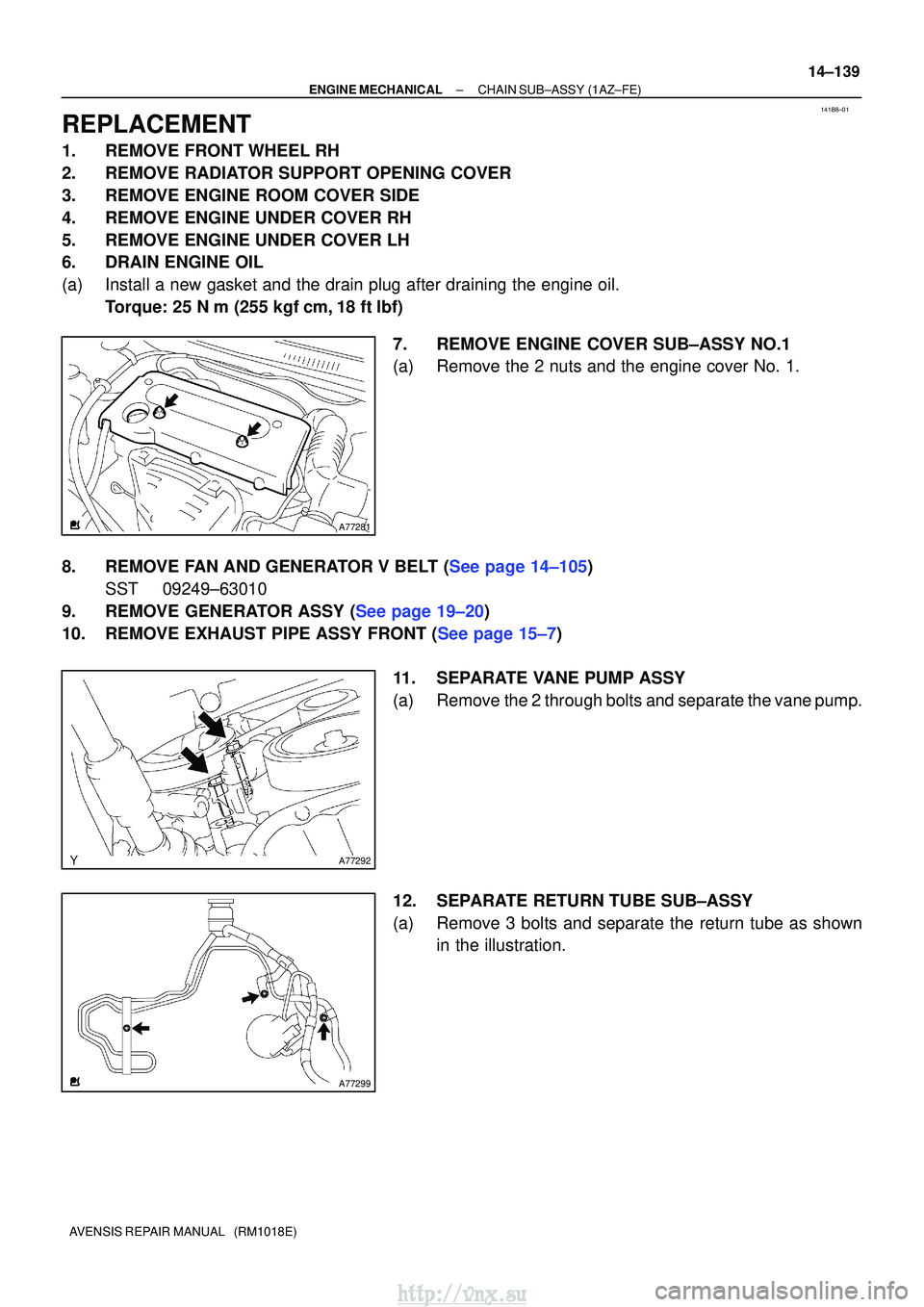
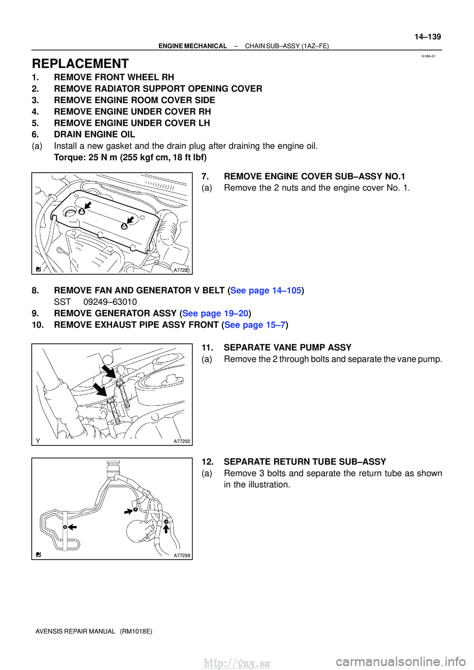
7.REMOVE ENGINE COVER SUB±ASSY NO.1
(a)Remove the 2 nuts and the engine cover No. 1.
8.REMOVE FAN AND GENERATOR V BELT (See page 14±105) SST 09249±63010
9.REMOVE GENERATOR ASSY (See page 19±20)
10.REMOVE EXHAUST PIPE ASSY FRONT (See page 15±7)
11. SEPARATE VANE PUMP ASSY
(a) Remove the 2 through bolts and separate the vane pump.
12. SEPARATE RETURN TUBE SUB±ASSY
(a) Remove 3 bolts and separate the return tube as shownin the illustration.
http://vnx.su
Page 499 of 2234
A77303
A77308
A77306
A77307
14±140
±
ENGINE MECHANICAL CHAIN SUB±ASSY (1AZ±FE)
AVENSIS REPAIR MANUAL (RM1018E)
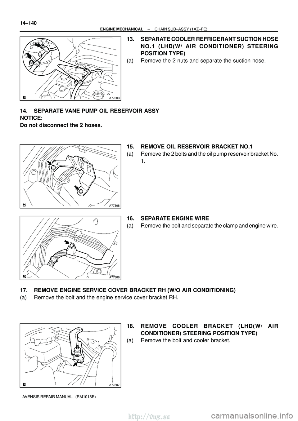
13. SEPARATE COOLER REFRIGERANT SUCTION HOSE NO.1 (LHD(W/ AIR CONDITIONER) STEERING
POSITION TYPE)
(a) Remove the 2 nuts and separate the suction hose.
14. SEPARATE VANE PUMP OIL RESERVOIR ASSY
NOTICE:
Do not disconnect the 2 hoses. 15. REMOVE OIL RESERVOIR BRACKET NO.1
(a) Remove the 2 bolts and the oil pump reservoir bracket No.1.
16. SEPARATE ENGINE WIRE
(a) Remove the bolt and separate the clamp and engine wire.
17. REMOVE ENGINE SERVICE COVER BRACKET RH (W/O AIR CONDITIONING)
(a) Remove the bolt and the engine service cover bracket RH. 18. REMOVE COOLER BRACKET (LHD(W/ AIRCONDITIONER) STEERING POSITION TYPE)
(a) Remove the bolt and cooler bracket.
http://vnx.su
Page 504 of 2234
A77382
Groove90
�
A77383
Groove
A66833
B11424
±
ENGINE MECHANICAL CHAIN SUB±ASSY (1AZ±FE)
14±145
AVENSIS REPAIR MANUAL (RM1018E)
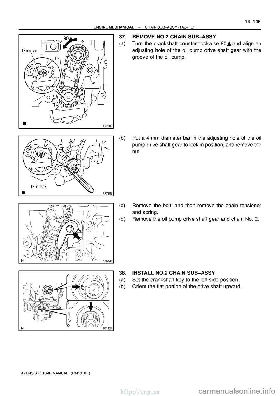
37. REMOVE NO.2 CHAIN SUB±ASSY
(a) Turn the crankshaft counterclockwise 90 �, and align an
adjusting hole of the oil pump drive shaft gear with the
groove of the oil pump.
(b) Put a 4 mm diameter bar in the adjusting hole of the oil pump drive shaft gear to lock in position, and remove the
nut.
(c) Remove the bolt, and then remove the chain tensioner and spring.
(d) Remove the oil pump drive shaft gear and chain No. 2.
38. INSTALL NO.2 CHAIN SUB±ASSY
(a) Set the crankshaft key to the left side position.
(b) Orient the flat portion of the drive shaft upward.
http://vnx.su
Page 505 of 2234
A77384
Mark Link
Timing Mark
Timing Mark
Mark Link
A77385
Groove
A77386
Groove
A77387
90 �
14±146
±
ENGINE MECHANICAL CHAIN SUB±ASSY (1AZ±FE)
AVENSIS REPAIR MANUAL (RM1018E)
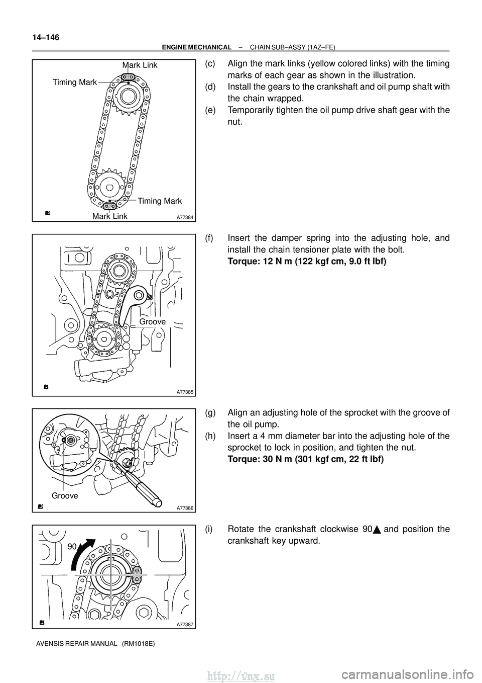
(c) Align the mark links (yellow colored links) with the timing marks of each gear as shown in the illustration.
(d) Install the gears to the crankshaft and oil pump shaft with
the chain wrapped.
(e) Temporarily tighten the oil pump drive shaft gear with the nut.
(f) Insert the damper spring into the adjusting hole, and install the chain tensioner plate with the bolt.
Torque: 12 N �m (122 kgf� cm, 9.0 ft�lbf)
(g) Align an adjusting hole of the sprocket with the groove of the oil pump.
(h) Insert a 4 mm diameter bar into the adjusting hole of the sprocket to lock in position, and tighten the nut.
Torque: 30 N �m (301 kgf� cm, 22 ft�lbf)
(i) Rotate the crankshaft clockwise 90� , and position the
crankshaft key upward.
http://vnx.su
Page 511 of 2234
A77399
Seal Packing
A77400NutNut
A
BC
A A
AAB
14±152
±
ENGINE MECHANICALCHAIN SUB±ASSY(1AZ±FE)
AVENSIS REPAIR MANUAL (RM1018E)
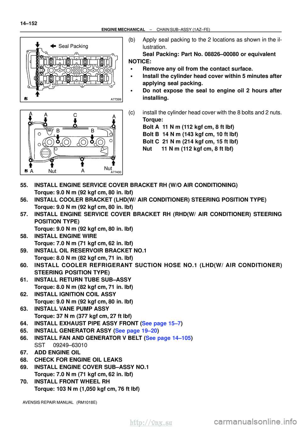
(b)Apply seal packing to the 2 locations as shown in the il- lustration.
Seal Packing: Part No. 08826±00080 or equivalent
NOTICE:
�Remove any oil from the contact surface.
�Install the cylinder head cover within 5 minutes after
applying seal packing.
�Do not expose the seal to engine oil 2 hours after
installing.
(c)install the cylinder head cover with the 8 bolts and 2 nuts. Torque:
Bolt A 11 N�m (112 kgf�cm, 8 ft�lbf)
Bolt B 14 N�m (143 kgf�cm, 10 ft�lbf)
Bolt C 21 N�m (214 kgf�cm, 15 ft�lbf)
Nut 11 N �m (112 kgf�cm, 8 ft �lbf)
55.INSTALL ENGINE SERVICE COVER BRACKET RH (W/O AIR CONDITIONING) Torque: 9.0 N �m (92 kgf�cm,80 in. �lbf)
56.INSTALL COOLER BRACKET (LHD(W/ AIR CONDITIONER) STEERING POSITION TYPE) Torque: 9.0 N �m (92 kgf�cm,80 in. �lbf)
57.INSTALL ENGINE SERVICE COVER BRACKET RH (RHD(W/ AIR CONDITIONER) STEERING
POSITION TYPE)
Torque: 9.0 N �m (92 kgf�cm,80 in. �lbf)
58.INSTALL ENGINE WIRE Torque: 7.0 N �m (71 kgf�cm,62 in. �lbf)
59.INSTALL OIL RESERVOIR BRACKET NO.1 Torque: 8.0 N �m (82 kgf�cm,71 in. �lbf)
60.IN STALL COOL ER REFRIGERANT SUCTION HOSE NO.1 (LHD(W/ AIR CONDITION ER)
STEERING POSITION TYPE)
61.INSTALL RETURN TUBE SUB±ASSY
Torque: 8.0 N �m (82 kgf�cm,71 in. �lbf)
62.INSTALL IGNITION COIL ASSY Torque: 9.0 N �m (92 kgf�cm,80 in. �lbf)
63.INSTALL VANE PUMP ASSY
Torque: 37 N �m (377 kgf�cm,27 ft�lbf)
64.INSTALL EXHAUST PIPE ASSY FRONT (See page 15±7)
65.INSTALL GENERATOR ASSY (See page 19±20)
66.INSTALL FAN AND GENERATOR V BELT (See page 14±105) SST 09249±63010
67. ADD ENGINE OIL
68. CHECK FOR ENGINE OIL LEAKS
69. INSTALL ENGINE COVER SUB±ASSY NO.1 Torque: 7.0 N �m (71 kgf �cm, 62 in. �lbf)
70. INSTALL FRONT WHEEL RH Torque: 103 N� m (1,050 kgf�cm, 76 ft �lbf)
http://vnx.su
Page 512 of 2234
141B8±01
A77281
A77292
A77299
±
ENGINE MECHANICALCHAIN SUB±ASSY(1AZ±FE)
14±139
AVENSIS REPAIR MANUAL (RM1018E)
REPLACEMENT
1.REMOVE FRONT WHEEL RH
2.REMOVE RADIATOR SUPPORT OPENING COVER
3.REMOVE ENGINE ROOM COVER SIDE
4.REMOVE ENGINE UNDER COVER RH
5.REMOVE ENGINE UNDER COVER LH
6.DRAIN ENGINE OIL
(a)Install a new gasket and the drain plug after draining the engine oil.
Torque: 25 N �m (255 kgf�cm,18 ft�lbf)
7.REMOVE ENGINE COVER SUB±ASSY NO.1
(a)Remove the 2 nuts and the engine cover No. 1.
8.REMOVE FAN AND GENERATOR V BELT (See page 14±105) SST 09249±63010
9.REMOVE GENERATOR ASSY (See page 19±20)
10.REMOVE EXHAUST PIPE ASSY FRONT (See page 15±7)
11. SEPARATE VANE PUMP ASSY
(a) Remove the 2 through bolts and separate the vane pump.
12. SEPARATE RETURN TUBE SUB±ASSY
(a) Remove 3 bolts and separate the return tube as shownin the illustration.
http://vnx.su