Page 83 of 2234
D25081
Spring Type Clamp
Clamp Track
D20025
CG
DLC3
TS
D30964
±
INTRODUCTION REPAIR INSTRUCTION
01±17
AVENSIS REPAIR MANUAL (RM1018E)
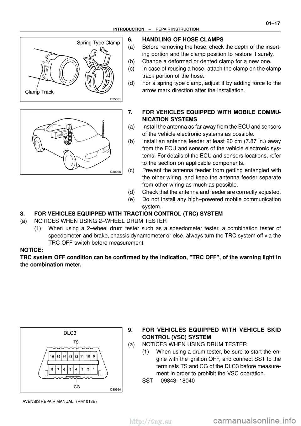
6. HANDLING OF HOSE CLAMPS
(a) Before removing the hose, check the depth of the insert-
ing portion and the clamp position to restore it surely.
(b) Change a deformed or dented clamp for a new one.
(c) In case of reusing a hose, attach the clamp on the clamp track portion of the hose.
(d) For a spring type clamp, adjust it by adding force to the
arrow mark direction after the installation.
7. FOR VEHICLES EQUIPPED WITH MOBILE COMMU- NICATION SYSTEMS
(a) Install the antenna as far away from the ECU and sensors of the vehicle electronic systems as possible.
(b) Install an antenna feeder at least 20 cm (7.87 in.) away from the ECU and sensors of the vehicle electronic sys-
tems. For details of the ECU and sensors locations, refer
to the section on applicable components.
(c) Prevent the antenna feeder from getting entangled with the other wiring, and keep the antenna feeder separate
from other wiring as much as possible.
(d) Check that the antenna and feeder are correctly adjusted.
(e) Do not install any high±powered mobile communication system.
8. FOR VEHICLES EQUIPPED WITH TRACTION CONTROL (TRC) SYSTEM
(a) NOTICES WHEN USING 2±WHEEL DRUM TESTER
(1) When using a 2±wheel drum tester such as a speedometer tester, a combination tester ofspeedometer and brake, chassis dynamometer or else, always turn the TRC system off via the
TRC OFF switch before measurement.
NOTICE:
TRC system OFF condition can be confirmed by the indication, ºTRC OFF\
º, of the warning light in
the combination meter.
9. FOR VEHICLES EQUIPPED WITH VEHICLE SKIDCONTROL (VSC) SYSTEM
(a) NOTICES WHEN USING DRUM TESTER
(1) When using a drum tester, be sure to start the en-gine with the ignition OFF, and connect SST to the
terminals TS and CG of the DLC3 before measure-
ment in order to prohibit the VSC operation.
SST 09843±18040
http://vnx.su
Page 85 of 2234
010B5±11
D25082
Rubber Attachment
D27697
: SUPPORT POSITION, PAN
TOGRAPH JACK POSITION
: CENTER OF VEHICLE GRAVITY
(unload condition)
: JACK POSITION
±
INTRODUCTION REPAIR INSTRUCTION
01±19
AVENSIS REPAIR MANUAL (RM1018E)
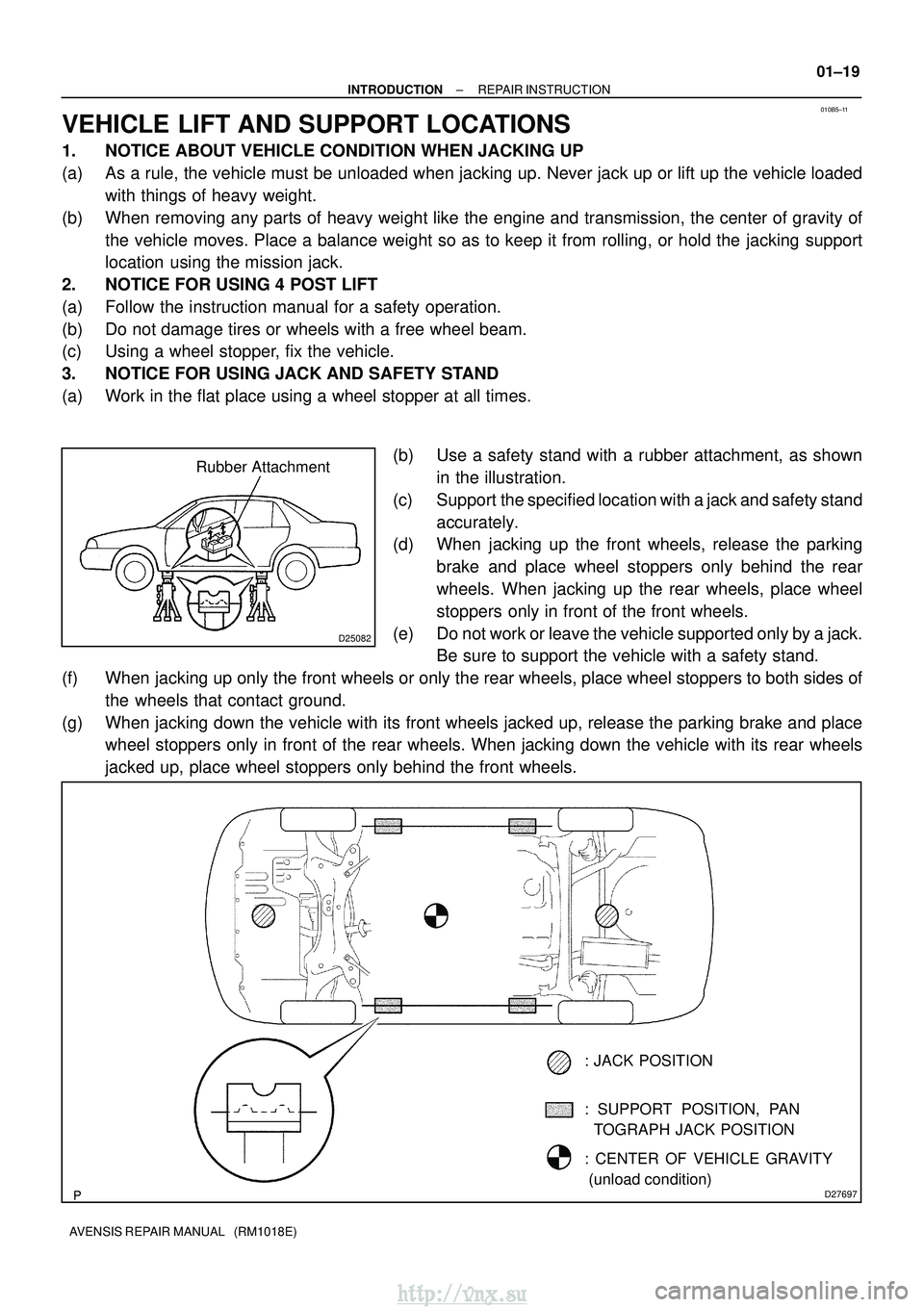
VEHICLE LIFT AND SUPPORT LOCATIONS
1. NOTICE ABOUT VEHICLE CONDITION WHEN JACKING UP
(a) As a rule, the vehicle must be unloaded when jacking up. Never jack up o\
r lift up the vehicle loaded
with things of heavy weight.
(b) When removing any parts of heavy weight like the engine and transmission, the center of gravity of the vehicle moves. Place a balance weight so as to keep it from rolling,\
or hold the jacking support
location using the mission jack.
2. NOTICE FOR USING 4 POST LIFT
(a) Follow the instruction manual for a safety operation.
(b) Do not damage tires or wheels with a free wheel beam.
(c) Using a wheel stopper, fix the vehicle.
3. NOTICE FOR USING JACK AND SAFETY STAND
(a) Work in the flat place using a wheel stopper at all times.
(b) Use a safety stand with a rubber attachment, as shownin the illustration.
(c) Support the specified location with a jack and safety stand accurately.
(d) When jacking up the front wheels, release the parking
brake and place wheel stoppers only behind the rear
wheels. When jacking up the rear wheels, place wheel
stoppers only in front of the front wheels.
(e) Do not work or leave the vehicle supported only by a jack. Be sure to support the vehicle with a safety stand.
(f) When jacking up only the front wheels or only the rear wheels, place wheel stoppers to both sides of the wheels that contact ground.
(g) When jacking down the vehicle with its front wheels jacked up, release t\
he parking brake and place wheel stoppers only in front of the rear wheels. When jacking down the v\
ehicle with its rear wheels
jacked up, place wheel stoppers only behind the front wheels.
http://vnx.su
Page 88 of 2234
01±38
±
INTRODUCTION TERMS
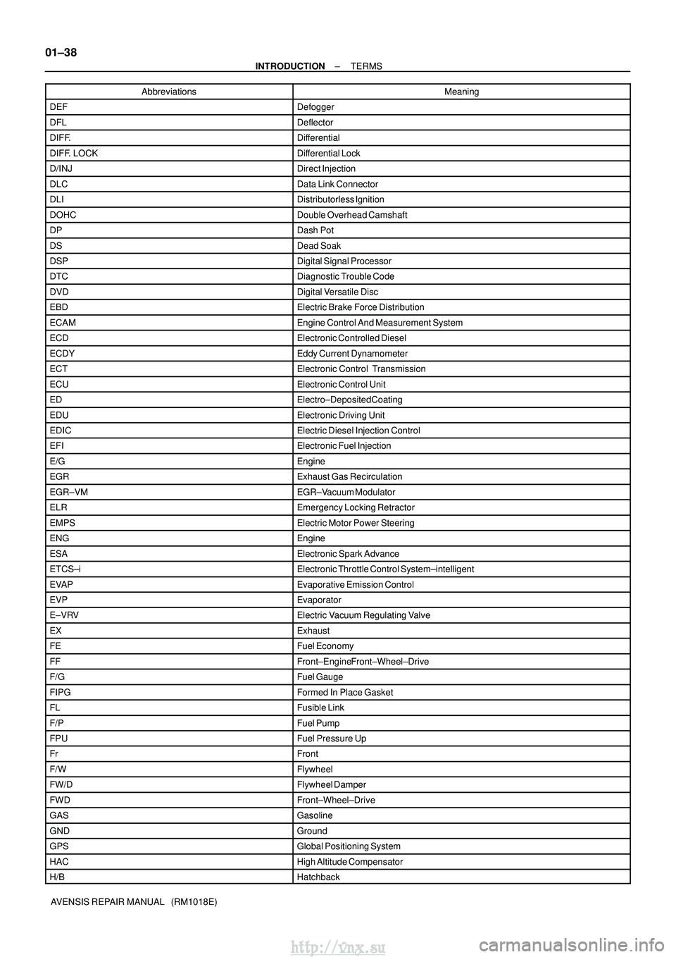
AVENSIS REPAIR MANUAL (RM1018E) Abbreviations Meaning
DEFDefogger
DFLDeflector
DIFF.Differential
DIFF. LOCKDifferential Lock
D/INJDirect Injection
DLCData Link Connector
DLIDistributorless Ignition
DOHCDouble Overhead Camshaft
DPDash Pot
DSDead Soak
DSPDigital Signal Processor
DTCDiagnostic Trouble Code
DVDDigital Versatile Disc
EBDElectric Brake Force Distribution
ECAMEngine Control And Measurement System
ECDElectronic Controlled Diesel
ECDYEddy Current Dynamometer
ECTElectronic Control Transmission
ECUElectronic Control Unit
EDElectro±Deposited Coating
EDUElectronic Driving Unit
EDICElectric Diesel Injection Control
EFIElectronic Fuel Injection
E/GEngine
EGRExhaust Gas Recirculation
EGR±VMEGR±Vacuum Modulator
ELREmergency Locking Retractor
EMPSElectric Motor Power Steering
ENGEngine
ESAElectronic Spark Advance
ETCS±iElectronic Throttle Control System±intelligent
EVAPEvaporative Emission Control
EVPEvaporator
E±VRVElectric Vacuum Regulating Valve
EXExhaust
FEFuel Economy
FFFront±Engine Front±Wheel±Drive
F/GFuel Gauge
FIPGFormed In Place Gasket
FLFusible Link
F/PFuel Pump
FPUFuel Pressure Up
FrFront
F/WFlywheel
FW/DFlywheel Damper
FWDFront±Wheel±Drive
GASGasoline
GNDGround
GPSGlobal Positioning System
HACHigh Altitude Compensator
H/BHatchback
http://vnx.su
Page 90 of 2234
01±40
±
INTRODUCTION TERMS
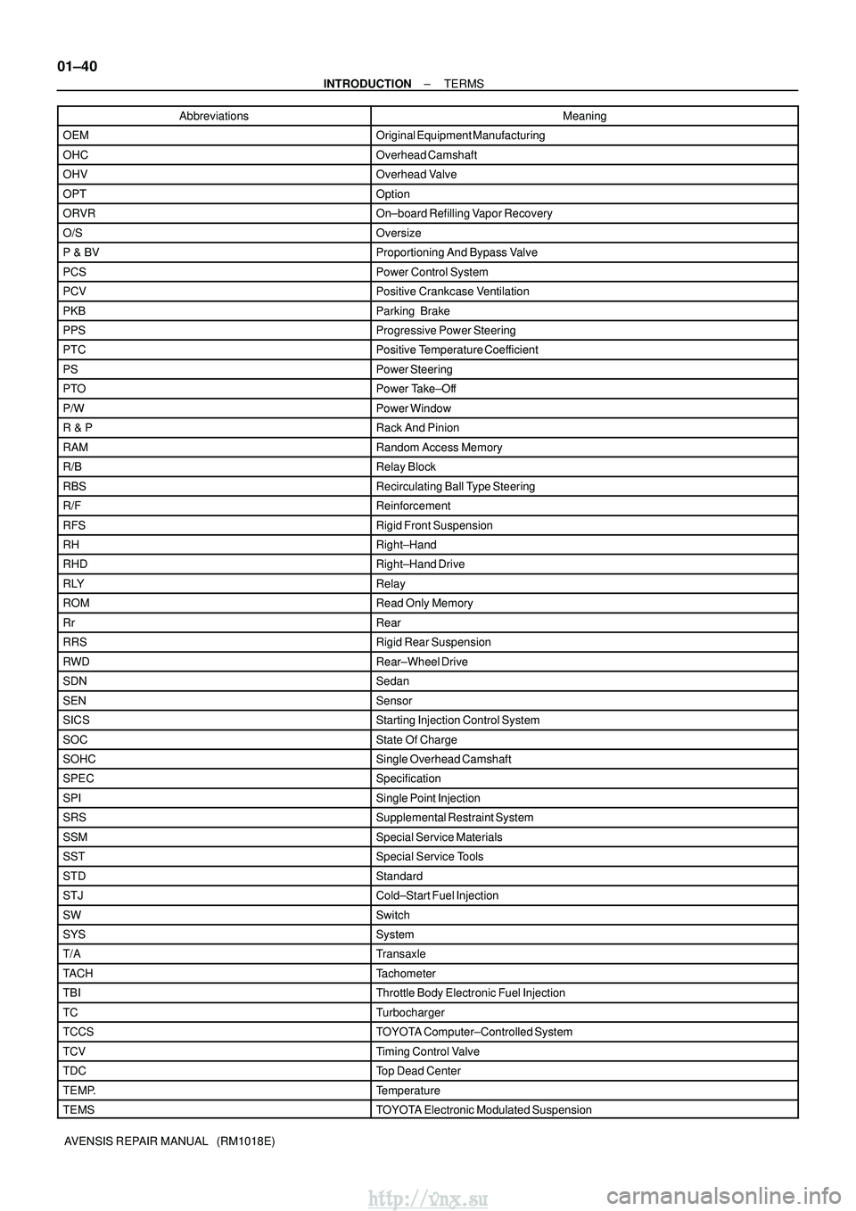
AVENSIS REPAIR MANUAL (RM1018E) Abbreviations Meaning
OEMOriginal Equipment Manufacturing
OHCOverhead Camshaft
OHVOverhead Valve
OPTOption
ORVROn±board Refilling Vapor Recovery
O/SOversize
P & BVProportioning And Bypass Valve
PCSPower Control System
PCVPositive Crankcase Ventilation
PKBParking Brake
PPSProgressive Power Steering
PTCPositive Temperature Coefficient
PSPower Steering
PTOPower Take±Off
P/WPower Window
R & PRack And Pinion
RAMRandom Access Memory
R/BRelay Block
RBSRecirculating Ball Type Steering
R/FReinforcement
RFSRigid Front Suspension
RHRight±Hand
RHDRight±Hand Drive
RLYRelay
ROMRead Only Memory
RrRear
RRSRigid Rear Suspension
RWDRear±Wheel Drive
SDNSedan
SENSensor
SICSStarting Injection Control System
SOCState Of Charge
SOHCSingle Overhead Camshaft
SPECSpecification
SPISingle Point Injection
SRSSupplemental Restraint System
SSMSpecial Service Materials
SSTSpecial Service Tools
STDStandard
STJCold±Start Fuel Injection
SWSwitch
SYSSystem
T/ATransaxle
TACHTachometer
TBIThrottle Body Electronic Fuel Injection
TCTurbocharger
TCCSTOYOTA Computer±Controlled System
TCVTiming Control Valve
TDCTop Dead Center
TEMP.Temperature
TEMSTOYOTA Electronic Modulated Suspension
http://vnx.su
Page 91 of 2234
±
INTRODUCTION TERMS
01±41
AVENSIS REPAIR MANUAL (RM1018E)Abbreviations Meaning
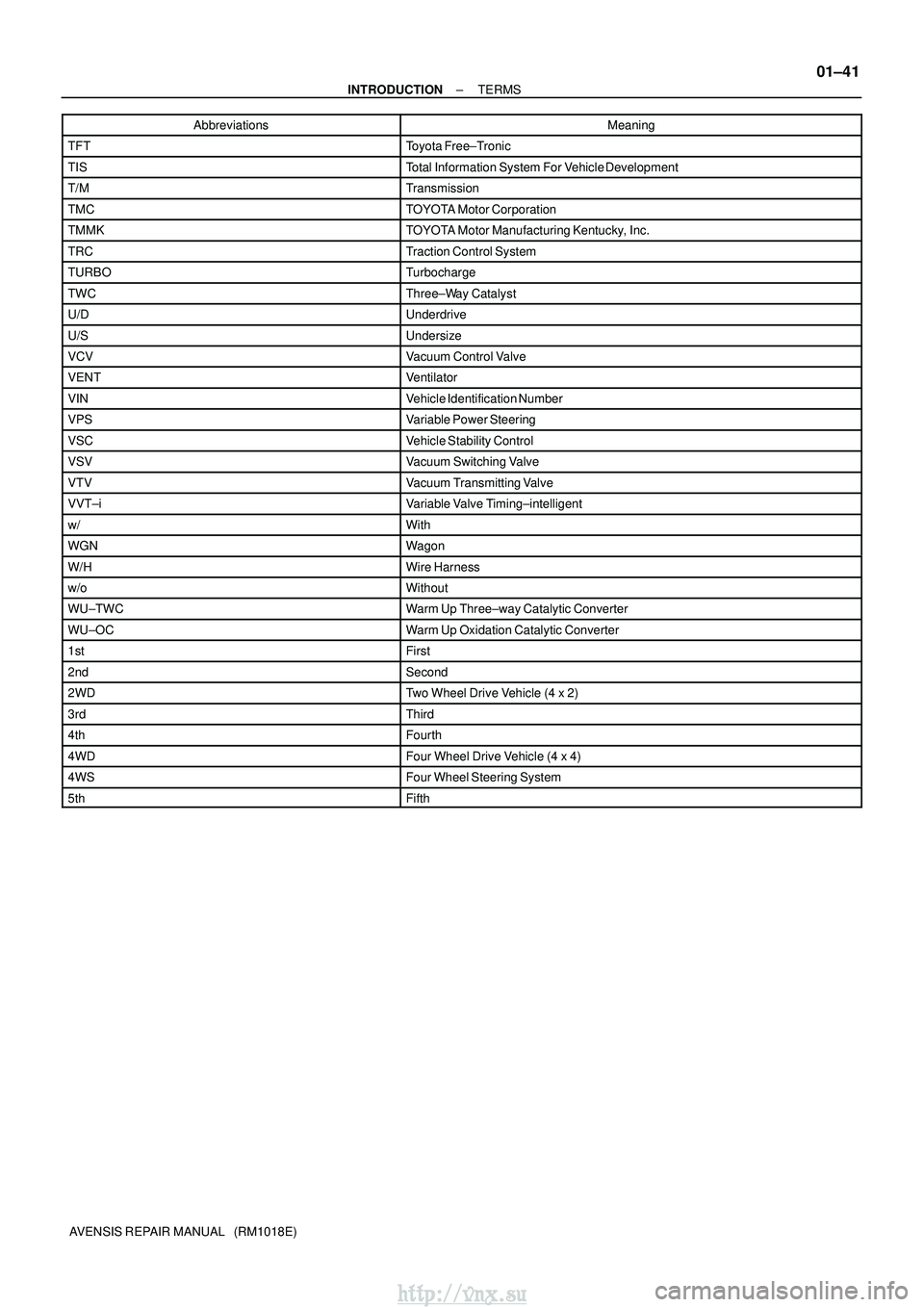
TFTToyota Free±Tronic
TISTotal Information System For Vehicle Development
T/MTransmission
TMCTOYOTA Motor Corporation
TMMKTOYOTA Motor Manufacturing Kentucky, Inc.
TRCTraction Control System
TURBOTurbocharge
TWCThree±Way Catalyst
U/DUnderdrive
U/SUndersize
VCVVacuum Control Valve
VENTVentilator
VINVehicle Identification Number
VPSVariable Power Steering
VSCVehicle Stability Control
VSVVacuum Switching Valve
VTVVacuum Transmitting Valve
VVT±iVariable Valve Timing±intelligent
w/With
WGNWagon
W/HWire Harness
w/oWithout
WU±TWCWarm Up Three±way Catalytic Converter
WU±OCWarm Up Oxidation Catalytic Converter
1stFirst
2ndSecond
2WDTwo Wheel Drive Vehicle (4 x 2)
3rdThird
4thFourth
4WDFour Wheel Drive Vehicle (4 x 4)
4WSFour Wheel Steering System
5thFifth
http://vnx.su
Page 147 of 2234
±
PREPARATION REAR SUSPENSION
02±27
AVENSIS REPAIR MANUAL (RM1018E)
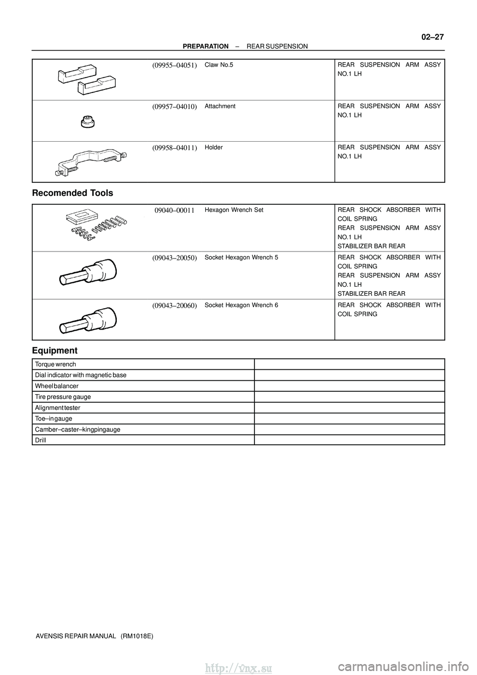
(09955±04051)Claw No.5REAR SUSPENSION ARM ASSY
NO.1 LH
(09957±04010)AttachmentREAR SUSPENSION ARM ASSY
NO.1 LH
(09958±04011)HolderREAR SUSPENSION ARM ASSY
NO.1 LH
Recomended Tools
09040±00011Hexagon Wrench SetREAR SHOCK ABSORBER WITH
COIL SPRING
REAR SUSPENSION ARM ASSY
NO.1 LH
STABILIZER BAR REAR
(09043±20050)Socket Hexagon Wrench 5REAR SHOCK ABSORBER WITH
COIL SPRING
REAR SUSPENSION ARM ASSY
NO.1 LH
STABILIZER BAR REAR
(09043±20060)Socket Hexagon Wrench 6REAR SHOCK ABSORBER WITH
COIL SPRING
Equipment
Torque wrench
Dial indicator with magnetic base
Wheel balancer
Tire pressure gauge
Alignment tester
Toe±in gauge
Camber±caster±kingpin gauge
Drill
http://vnx.su
Page 153 of 2234
±
PREPARATION SUPPLEMENTAL RESTRAINT SYSTEM
02±53
AVENSIS REPAIR MANUAL (RM1018E)
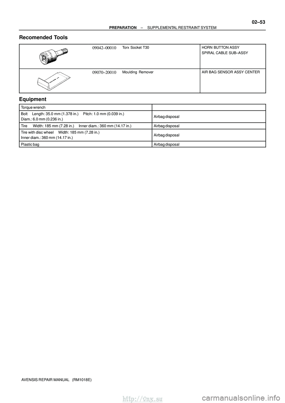
Recomended Tools
09042±00010Torx Socket T30HORN BUTTON ASSY
SPIRAL CABLE SUB±ASSY
09070±20010Moulding RemoverAIR BAG SENSOR ASSY CENTER
Equipment
Torque wrench
Bolt Length: 35.0 mm (1.378 in.) Pitch: 1.0 mm (0.039 in.)
Diam.: 6.0 mm (0.236 in.)Airbag disposal
Tire Width: 185 mm (7.28 in.) Inner diam.: 360 mm (14.17 in.)\
Airbag disposal
Tire with disc wheel Width: 185 mm (7.28 in.)
Inner diam.: 360 mm (14.17 in.)Airbag disposal
Plastic bagAirbag disposal
http://vnx.su
Page 154 of 2234
022KG±01
02±28
±
PREPARATION TIRE & WHEEL
AVENSIS REPAIR MANUAL (RM1018E)
TIRE & WHEEL
PREPARATION
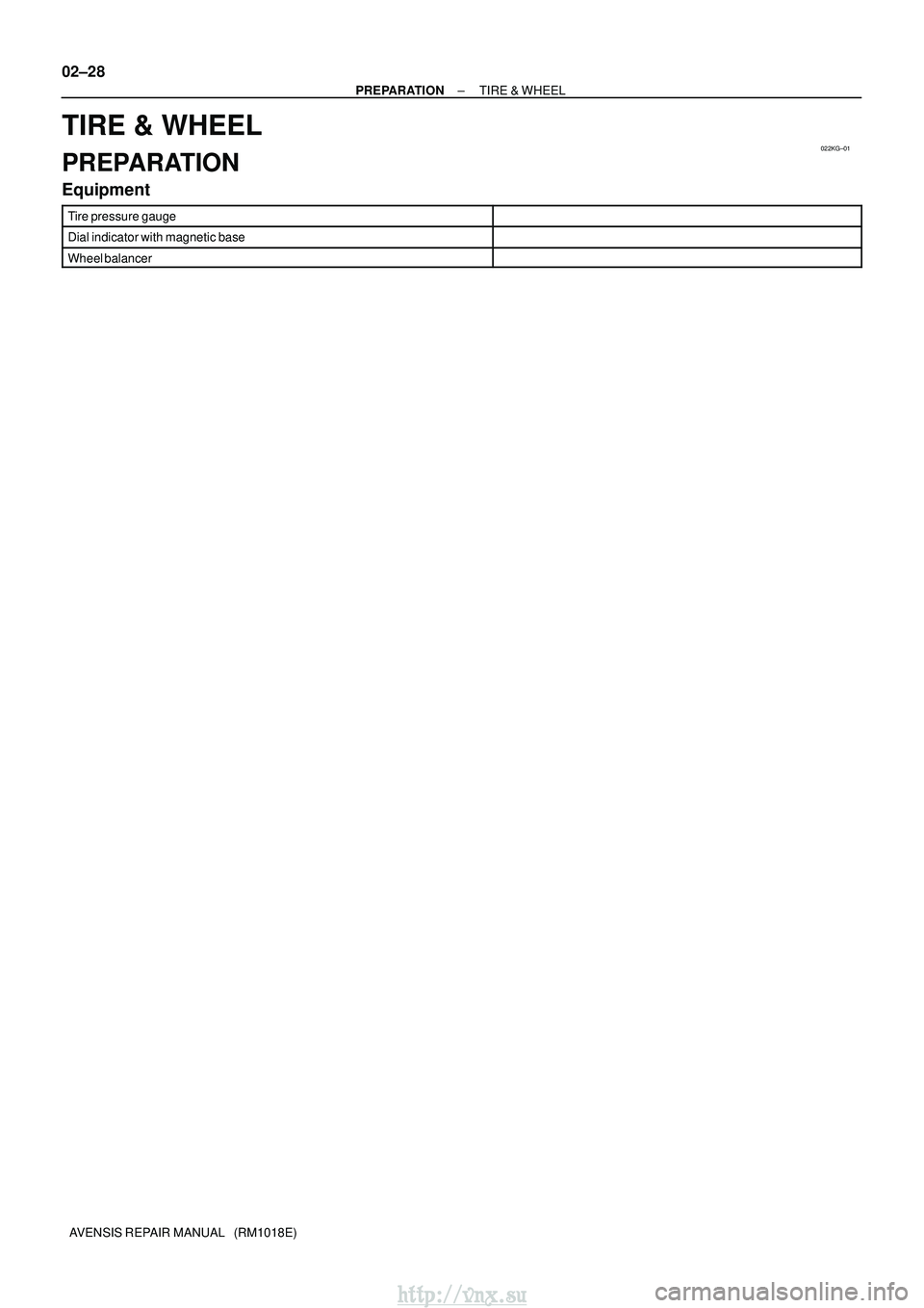
Equipment
Tire pressure gauge
Dial indicator with magnetic base
Wheel balancer
http://vnx.su