Page 84 of 2234
01±18
±
INTRODUCTION REPAIR INSTRUCTION
AVENSIS REPAIR MANUAL (RM1018E)
NOTICE:
�Confirm that the VSC warning light blinks.
�VSC system will be reset when the engine is re-
started.
�Fasten the vehicle with lock chains.
(b) NOTICES OF RELATED OPERATIONS TO VSC (1) Do not carry out unnecessary installation and re-
moval as it might disorder the adjustment of related
parts to VSC.
(2) Be sure to carry out the preparation for operation and the confirmation of operation completion in ac-
cordance with the instruction of the text and when
the related operations to VSC are performed.
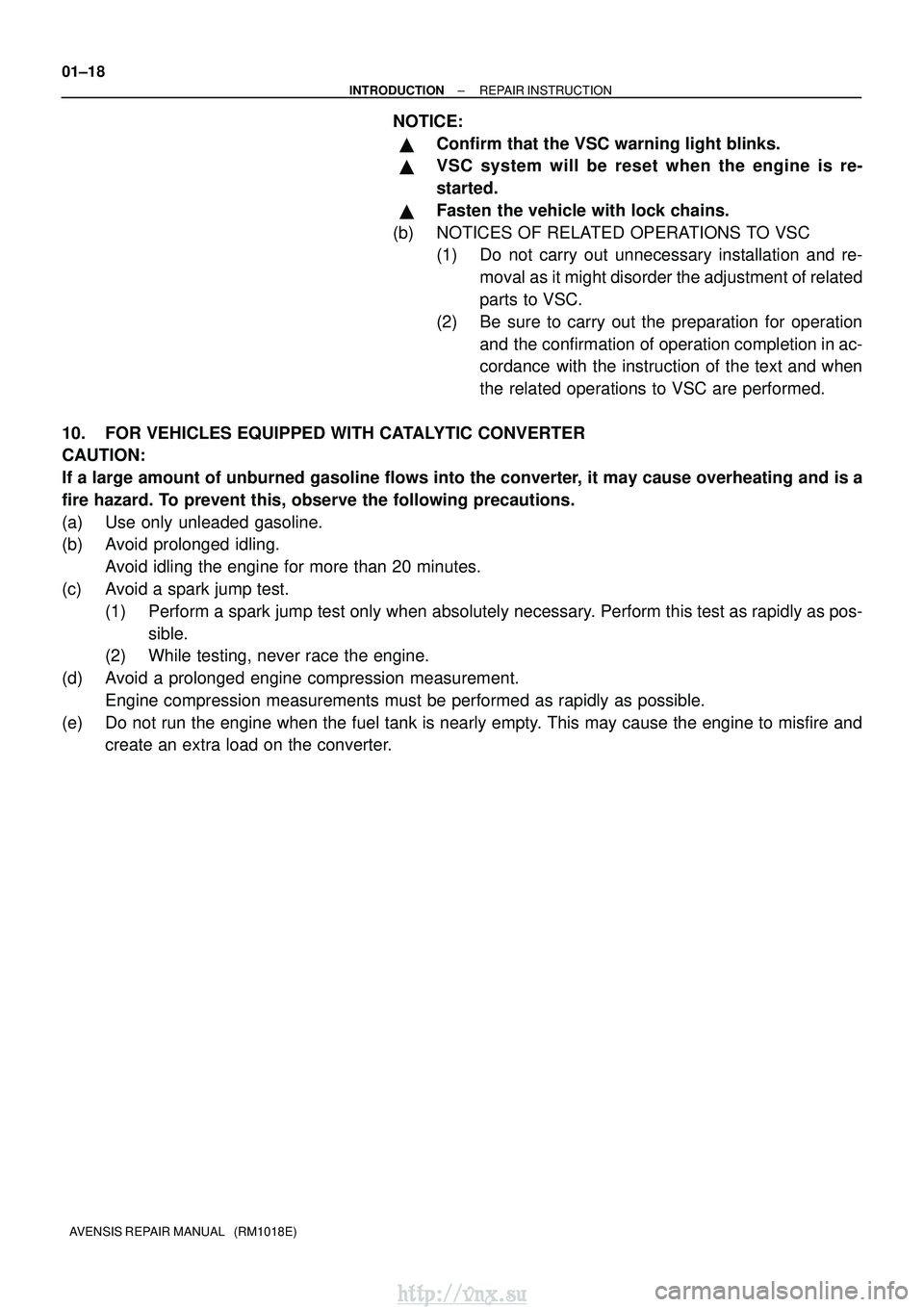
10. FOR VEHICLES EQUIPPED WITH CATALYTIC CONVERTER
CAUTION:
If a large amount of unburned gasoline flows into the converter, it may cause overheating and is a
fire hazard. To prevent this, observe the following precautions.
(a) Use only unleaded gasoline.
(b) Avoid prolonged idling. Avoid idling the engine for more than 20 minutes.
(c) Avoid a spark jump test. (1) Perform a spark jump test only when absolutely necessary. Perform this test as rapidly as pos-sible.
(2) While testing, never race the engine.
(d) Avoid a prolonged engine compression measurement. Engine compression measurements must be performed as rapidly as possible\
.
(e) Do not run the engine when the fuel tank is nearly empty. This may cause the engine to misfire and create an extra load on the converter.
http://vnx.su
Page 89 of 2234
±
INTRODUCTION TERMS
01±39
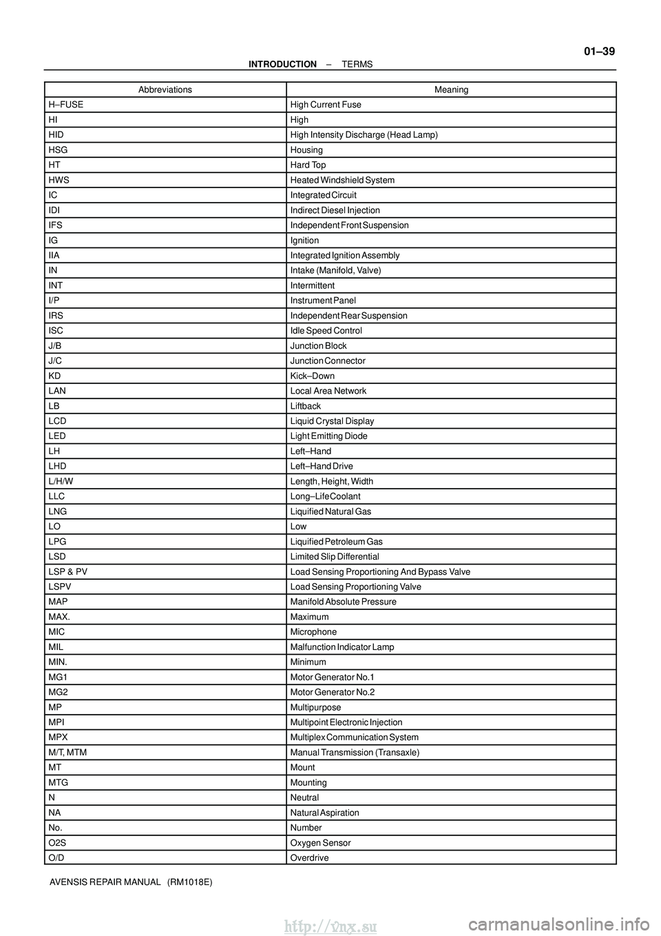
AVENSIS REPAIR MANUAL (RM1018E)Abbreviations Meaning
H±FUSEHigh Current Fuse
HIHigh
HIDHigh Intensity Discharge (Head Lamp)
HSGHousing
HTHard Top
HWSHeated Windshield System
ICIntegrated Circuit
IDIIndirect Diesel Injection
IFSIndependent Front Suspension
IGIgnition
IIAIntegrated Ignition Assembly
INIntake (Manifold, Valve)
INTIntermittent
I/PInstrument Panel
IRSIndependent Rear Suspension
ISCIdle Speed Control
J/BJunction Block
J/CJunction Connector
KDKick±Down
LANLocal Area Network
LBLiftback
LCDLiquid Crystal Display
LEDLight Emitting Diode
LHLeft±Hand
LHDLeft±Hand Drive
L/H/WLength, Height, Width
LLCLong±Life Coolant
LNGLiquified Natural Gas
LOLow
LPGLiquified Petroleum Gas
LSDLimited Slip Differential
LSP & PVLoad Sensing Proportioning And Bypass Valve
LSPVLoad Sensing Proportioning Valve
MAPManifold Absolute Pressure
MAX.Maximum
MICMicrophone
MILMalfunction Indicator Lamp
MIN.Minimum
MG1Motor Generator No.1
MG2Motor Generator No.2
MPMultipurpose
MPIMultipoint Electronic Injection
MPXMultiplex Communication System
M/T, MTMManual Transmission (Transaxle)
MTMount
MTGMounting
NNeutral
NANatural Aspiration
No.Number
O2SOxygen Sensor
O/DOverdrive
http://vnx.su
Page 95 of 2234
022KX±01
±
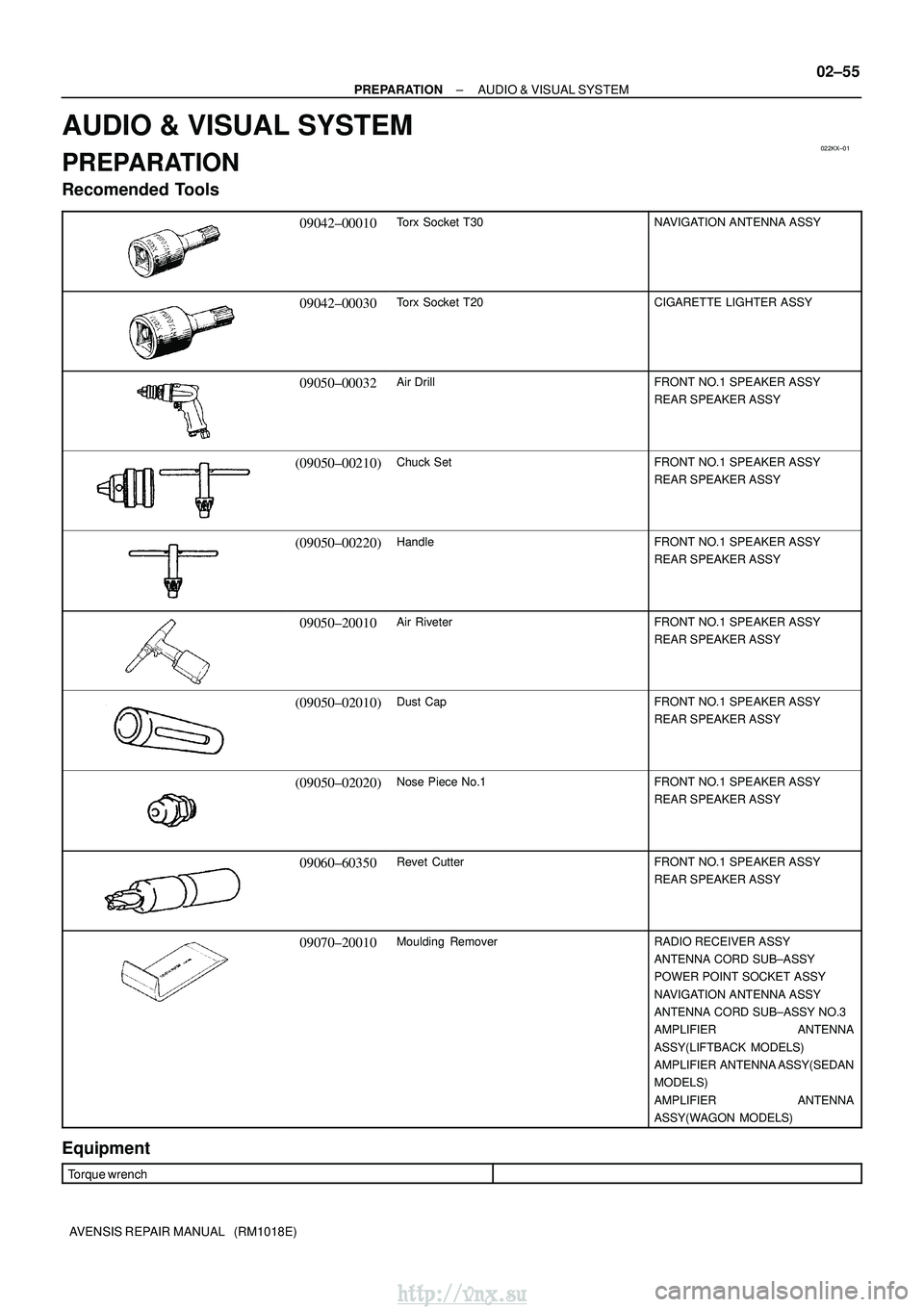
PREPARATION AUDIO & VISUAL SYSTEM
02±55
AVENSIS REPAIR MANUAL (RM1018E)
AUDIO & VISUAL SYSTEM
PREPARATION
Recomended Tools
09042±00010Torx Socket T30NAVIGATION ANTENNA ASSY
09042±00030Torx Socket T20CIGARETTE LIGHTER ASSY
09050±00032Air DrillFRONT NO.1 SPEAKER ASSY
REAR SPEAKER ASSY
(09050±00210)Chuck SetFRONT NO.1 SPEAKER ASSY
REAR SPEAKER ASSY
(09050±00220)HandleFRONT NO.1 SPEAKER ASSY
REAR SPEAKER ASSY
09050±20010Air RiveterFRONT NO.1 SPEAKER ASSY
REAR SPEAKER ASSY
(09050±02010)Dust CapFRONT NO.1 SPEAKER ASSY
REAR SPEAKER ASSY
(09050±02020)Nose Piece No.1FRONT NO.1 SPEAKER ASSY
REAR SPEAKER ASSY
09060±60350Revet CutterFRONT NO.1 SPEAKER ASSY
REAR SPEAKER ASSY
09070±20010Moulding RemoverRADIO RECEIVER ASSY
ANTENNA CORD SUB±ASSY
POWER POINT SOCKET ASSY
NAVIGATION ANTENNA ASSY
ANTENNA CORD SUB±ASSY NO.3
AMPLIFIER ANTENNA
ASSY(LIFTBACK MODELS)
AMPLIFIER ANTENNA ASSY(SEDAN
MODELS)
AMPLIFIER ANTENNA
ASSY(WAGON MODELS)
Equipment
Torque wrench
http://vnx.su
Page 166 of 2234
030MU±02
±
SERVICE SPECIFICATIONS BRAKE
03±41
AVENSIS REPAIR MANUAL (RM1018E)
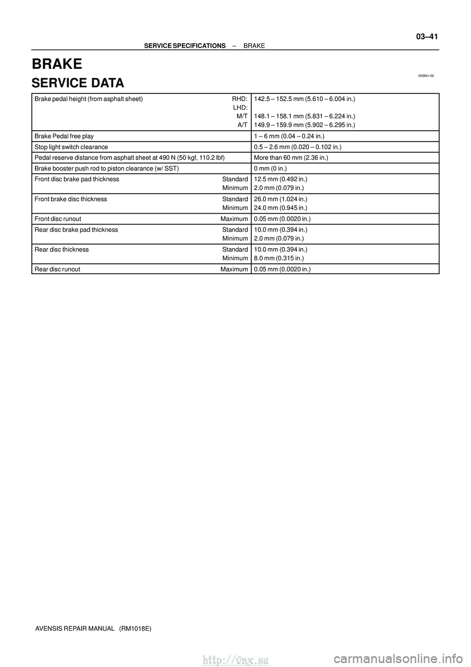
BRAKE
SERVICE DATA
Brake pedal height (from asphalt sheet) RHD:
LHD: M/T
A/T142.5 ± 152.5 mm (5.610 ± 6.004 in.)
148.1 ± 158.1 mm (5.831 ± 6.224 in.)
149.9 ± 159.9 mm (5.902 ± 6.295 in.)
Brake Pedal free play1 ± 6 mm (0.04 ± 0.24 in.)
Stop light switch clearance0.5 ± 2.6 mm (0.020 ± 0.102 in.)
Pedal reserve distance from asphalt sheet at 490 N (50 kgf, 110.2 lbf)More than 60 mm (2.36 in.)
Brake booster push rod to piston clearance (w/ SST)0 mm (0 in.)
Front disc brake pad thickness Standard
Minimum12.5 mm (0.492 in.)
2.0 mm (0.079 in.)
Front brake disc thickness Standard
Minimum26.0 mm (1.024 in.)
24.0 mm (0.945 in.)
Front disc runout Maximum0.05 mm (0.0020 in.)
Rear disc brake pad thickness Standard
Minimum10.0 mm (0.394 in.)
2.0 mm (0.079 in.)
Rear disc thickness Standard
Minimum10.0 mm (0.394 in.)
8.0 mm (0.315 in.)
Rear disc runout Maximum0.05 mm (0.0020 in.)
http://vnx.su
Page 206 of 2234
031HC±01
±
SERVICE SPECIFICATIONS LIGHTING
03±65
AVENSIS REPAIR MANUAL (RM1018E)
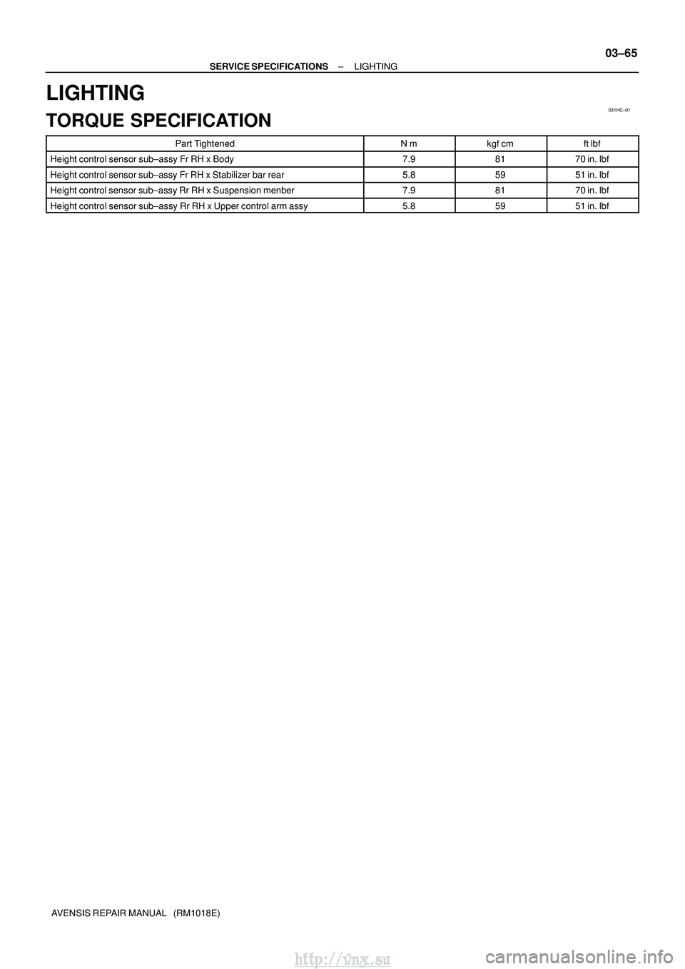
LIGHTING
TORQUE SPECIFICATION
Part TightenedN�mkgf �cmft �lbf
Height control sensor sub±assy Fr RH x Body7.98170 in.� lbf
Height control sensor sub±assy Fr RH x Stabilizer bar rear5.85951 in.�lbf
Height control sensor sub±assy Rr RH x Suspension menber7.98170 in.�lbf
Height control sensor sub±assy Rr RH x Upper control arm assy5.85951 in.�lbf
http://vnx.su
Page 241 of 2234
±
ENGINE CONTROL SYSTEMECD SYSTEM(1CD±FTV)
10±55
AVENSIS REPAIR MANUAL (RM1018E)
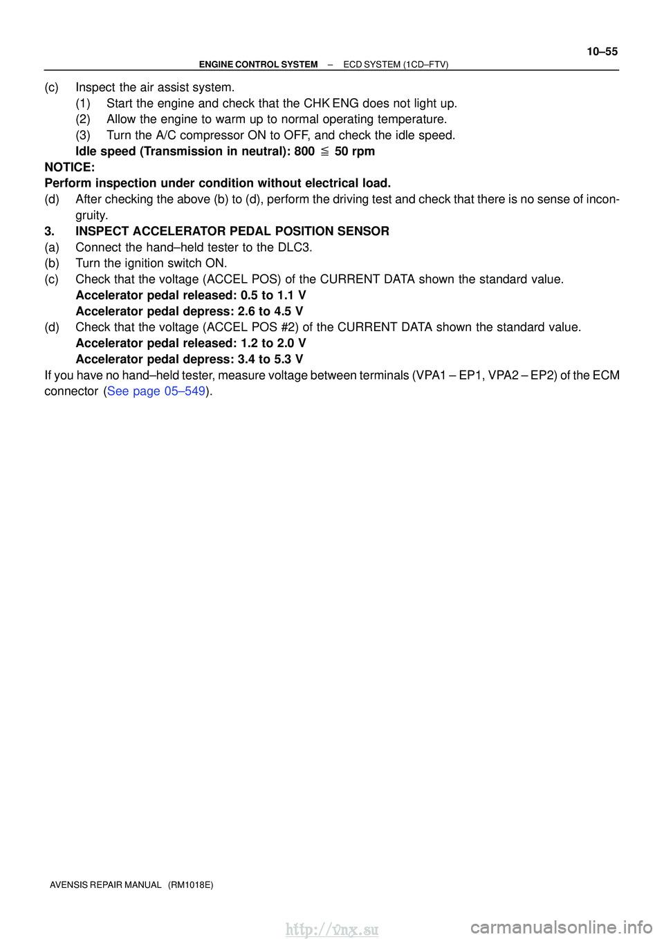
(c)Inspect the air assist system.
(1)Start the engine and check that the CHKENG does not light up.
(2)Allow the engine to warm up to normal operating temperature.
(3)Turn the A/C compressor ON to OFF, and check the idle speed.
Idle speed (Transmission in neutral): 800 � 50 rpm
NOTICE:
Perform inspection under condition without electrical load.
(d)After checking the above (b) to (d), perform the driving test and check that there is no sense of incon- gruity.
3.INSPECT ACCELERATOR PEDAL POSITION SENSOR
(a)Connect the hand±held tester to the DLC3.
(b)Turn the ignition switch ON.
(c)Check that the voltage (ACCEL POS) of the CURRENT DATA shown the standard value. Accelerator pedal released: 0.5 to 1.1 V
Accelerator pedal depress: 2.6 to 4.5 V
(d)Check that the voltage (ACCEL POS #2) of the CURRENT DATA shown the standard value.
Accelerator pedal released: 1.2 to 2.0 V
Accelerator pedal depress: 3.4 to 5.3 V
If you have no hand±held tester, measure voltage between terminals (VPA1 ± EP1, VPA2 ± EP2) of the ECM
connector (See page 05±549).
http://vnx.su
Page 278 of 2234
A53763
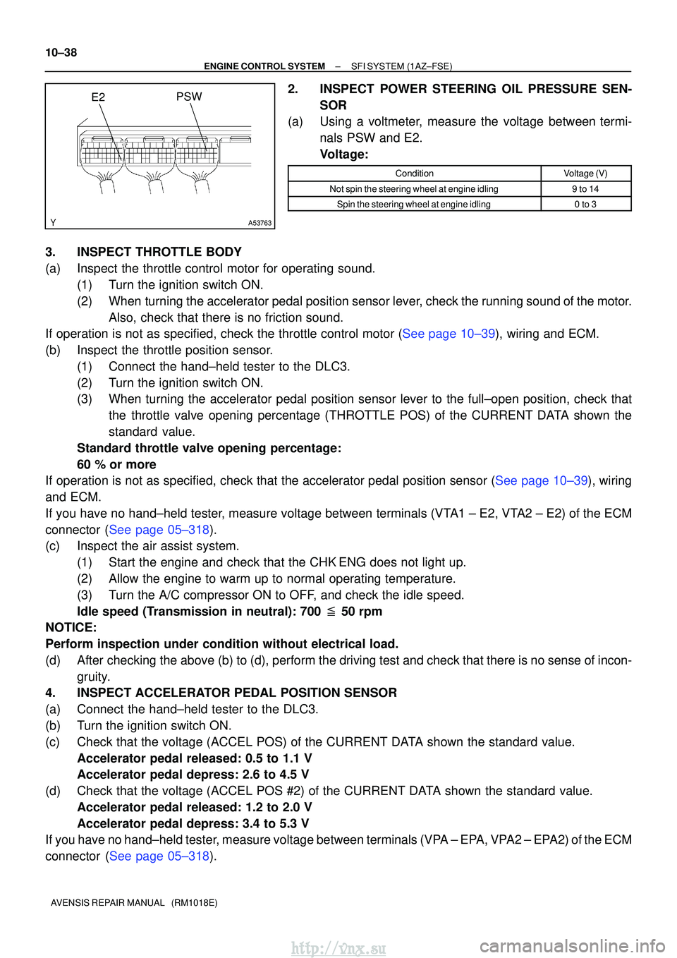
E2PSW
10±38
±
ENGINE CONTROL SYSTEMSFI SYSTEM(1AZ±FSE)
AVENSIS REPAIR MANUAL (RM1018E)
2.INSPECT POWER STEERING OIL PRESSURE SEN- SOR
(a)Using a voltmeter, measure the voltage between termi-
nals PSW and E2.
Voltage:
ConditionVoltage (V)
Not spin the steering wheel at engine idling9 to 14
Spin the steering wheel at engine idling0 to 3
3.INSPECT THROTTLE BODY
(a)Inspect the throttle control motor for operating sound.(1)Turn the ignition switch ON.
(2)When turning the accelerator pedal position sensor lever, check the running sound of the motor.Also, check that there is no friction sound.
If operation is not as specified, check the throttle control motor (See page 10±39), wiring and ECM.
(b) Inspect the throttle position sensor.
(1) Connect the hand±held tester to the DLC3.
(2) Turn the ignition switch ON.
(3) When turning the accelerator pedal position sensor lever to the full±\
open position, check thatthe throttle valve opening percentage (THROTTLE POS) of the CURRENT DATA shown the
standard value.
Standard throttle valve opening percentage:
60 % or more
If operation is not as specified, check that the accelerator pedal positio\
n sensor (See page 10±39), wiring
and ECM.
If you have no hand±held tester, measure voltage between terminals (VTA1 ± E2, VTA2 ± E2) of the ECM
connector (See page 05±318).
(c) Inspect the air assist system.
(1) Start the engine and check that the CHK ENG does not light up.
(2) Allow the engine to warm up to normal operating temperature.
(3) Turn the A/C compressor ON to OFF, and check the idle speed.
Idle speed (Transmission in neutral): 700 � 50 rpm
NOTICE:
Perform inspection under condition without electrical load.
(d) After checking the above (b) to (d), perform the driving test and check that there is no sense of incon-
gruity.
4. INSPECT ACCELERATOR PEDAL POSITION SENSOR
(a) Connect the hand±held tester to the DLC3.
(b) Turn the ignition switch ON.
(c) Check that the voltage (ACCEL POS) of the CURRENT DATA shown the standard value.
Accelerator pedal released: 0.5 to 1.1 V
Accelerator pedal depress: 2.6 to 4.5 V
(d) Check that the voltage (ACCEL POS #2) of the CURRENT DATA shown the standard value. Accelerator pedal released: 1.2 to 2.0 V
Accelerator pedal depress: 3.4 to 5.3 V
If you have no hand±held tester, measure voltage between terminals (VPA ± EPA, VPA2 ± EPA2) of the ECM
connector (See page 05±318).
http://vnx.su
Page 312 of 2234
110UD±01
A79188
A80091SST
A79190
11±82
±
FUEL FUEL FILTER ASSY (1CD±FTV)
AVENSIS REPAIR MANUAL (RM1018E)
FUEL FILTER ASSY (1CD±FTV)
REPLACEMENT
1. REMOVE AIR CLEANER ASSY
(a) Disconnect the connector.
(b) Remove the air cleaner cap with the air cleaner hose.
(c) Remove the air cleaner filter element.
(d) Remove the 3 bolts and the air cleaner case.
2. REMOVE FUEL FILTER ASSY
(a) Disconnect the 2 fuel hose from the fuel filter. (STD or COLD)
(b) Disconnect the 3 fuel hose from the fuel filter. (W/ ADDTIONAL HEATER)
(c) Disconnect the 2 connectors.
(d) Remove the 2 bolts and the fuel filter.
3. DRAIN FUEL
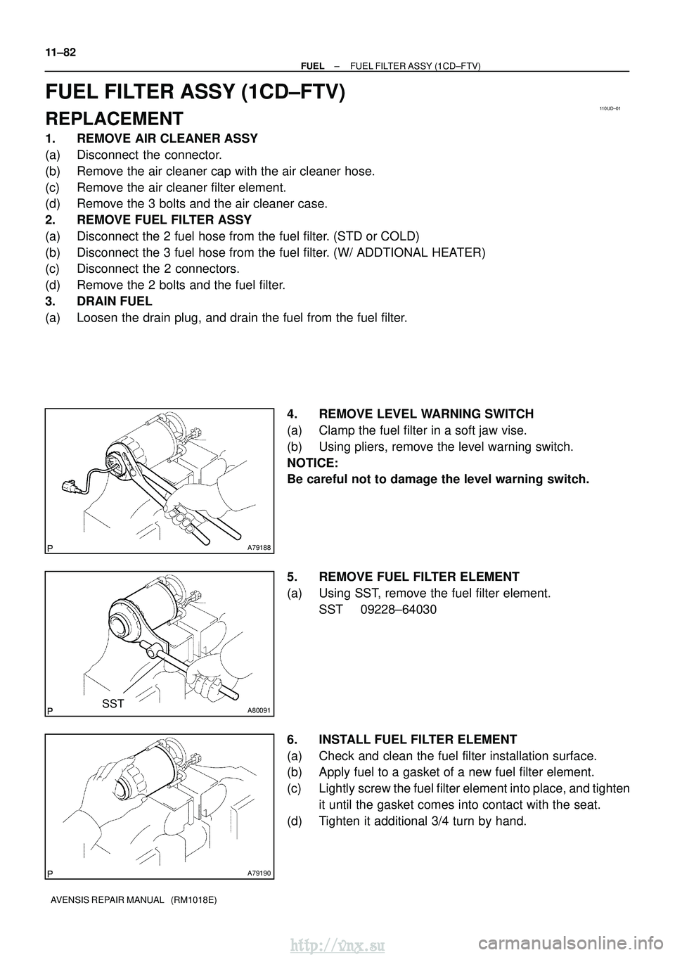
(a) Loosen the drain plug, and drain the fuel from the fuel filter. 4. REMOVE LEVEL WARNING SWITCH
(a) Clamp the fuel filter in a soft jaw vise.
(b) Using pliers, remove the level warning switch.
NOTICE:
Be careful not to damage the level warning switch.
5. REMOVE FUEL FILTER ELEMENT
(a) Using SST, remove the fuel filter element.SST 09228±64030
6. INSTALL FUEL FILTER ELEMENT
(a) Check and clean the fuel filter installation surface.
(b) Apply fuel to a gasket of a new fuel filter element.
(c) Lightly screw the fuel filter element into place, and tighten it until the gasket comes into contact with the seat.
(d) Tighten it additional 3/4 turn by hand.
http://vnx.su