Page 601 of 2234
14±104
±
ENGINE MECHANICAL ENGINE (1AZ±FE)
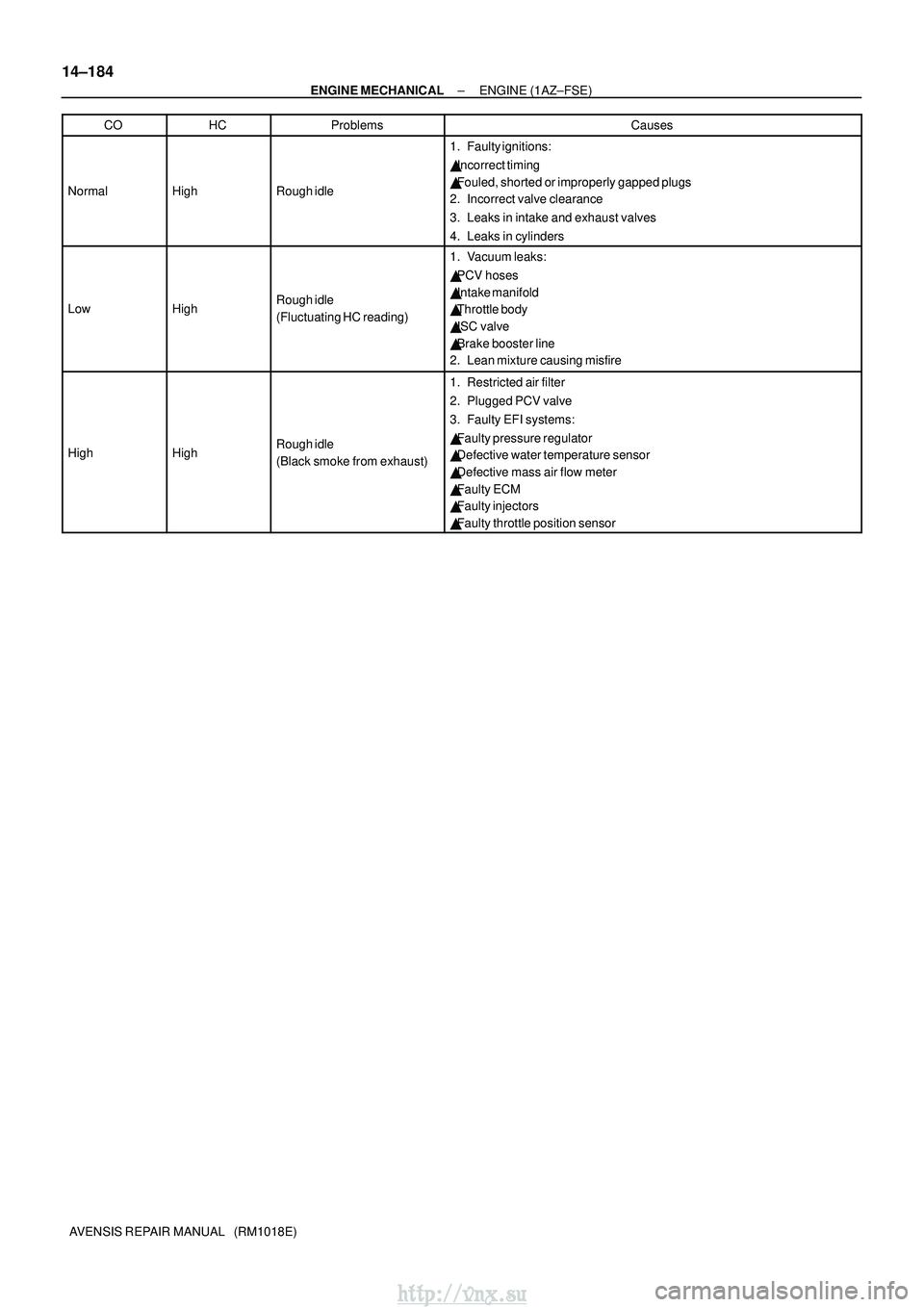
AVENSIS REPAIR MANUAL (RM1018E) CO
HCProblemsCauses
NormalHighRough idle
1. Faulty ignitions:
�
Incorrect timing
� Fouled, shorted or improperly gapped plugs
2. Incorrect valve clearance
3. Leaks in intake and exhaust valves
4. Leaks in cylinders
LowHighRough idle
(Fluctuating HC reading)
1. Vacuum leaks:
� PCV hoses
� Intake manifold
� Throttle body
� ISC valve
� Brake booster line
2. Lean mixture causing misfire
HighHighRough idle
(Black smoke from exhaust)
1. Restricted air filter
2. Plugged PCV valve
3. Faulty EFI systems:
� Faulty pressure regulator
� Defective water temperature sensor
� Defective mass air flow meter
� Faulty ECM
� Faulty injectors
� Faulty throttle position sensor
http://vnx.su
Page 605 of 2234
14±184
±
ENGINE MECHANICAL ENGINE (1AZ±FSE)
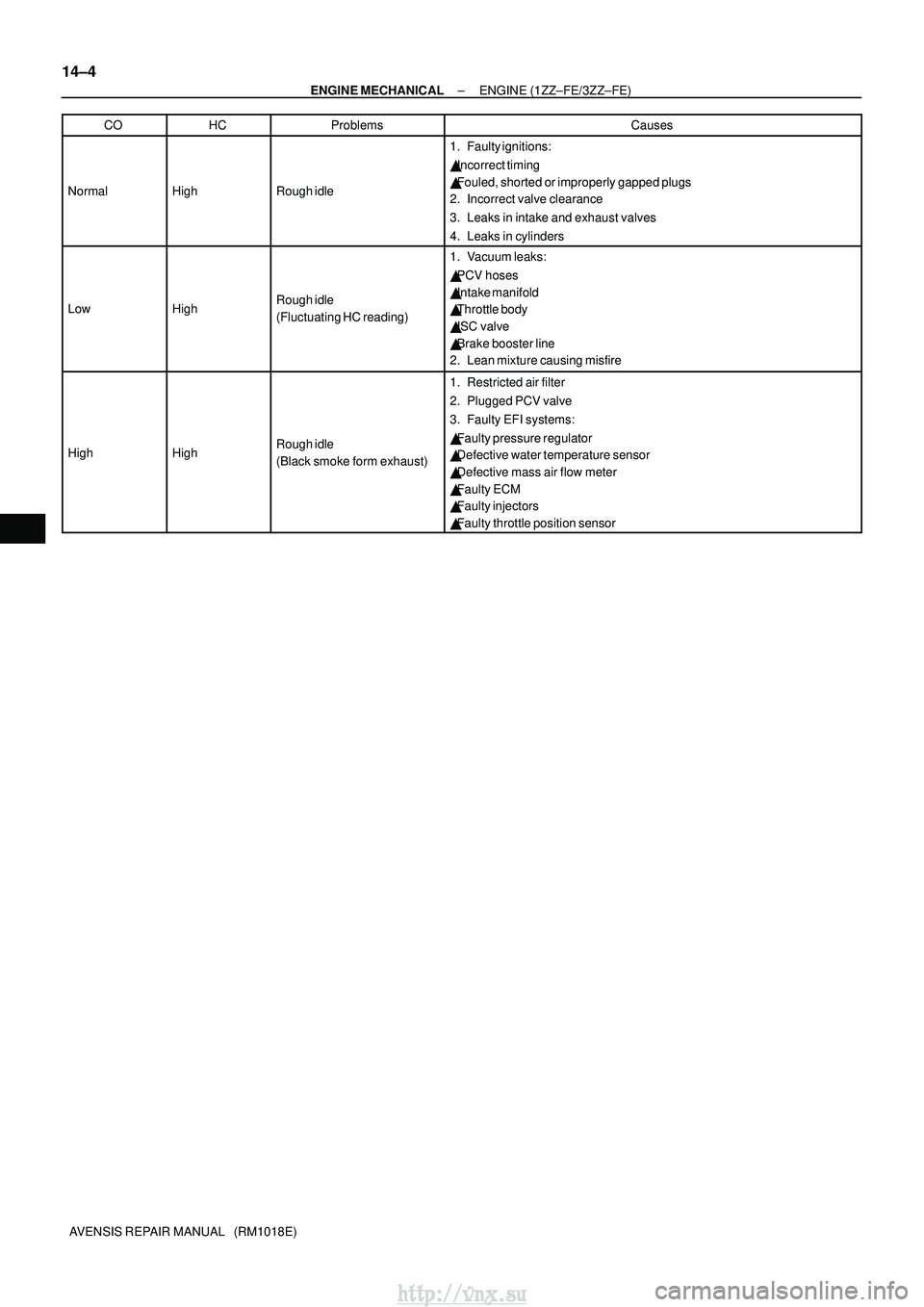
AVENSIS REPAIR MANUAL (RM1018E) CO
HCProblemsCauses
NormalHighRough idle
1. Faulty ignitions:
�
Incorrect timing
� Fouled, shorted or improperly gapped plugs
2. Incorrect valve clearance
3. Leaks in intake and exhaust valves
4. Leaks in cylinders
LowHighRough idle
(Fluctuating HC reading)
1. Vacuum leaks:
� PCV hoses
� Intake manifold
� Throttle body
� ISC valve
� Brake booster line
2. Lean mixture causing misfire
HighHighRough idle
(Black smoke from exhaust)
1. Restricted air filter
2. Plugged PCV valve
3. Faulty EFI systems:
� Faulty pressure regulator
� Defective water temperature sensor
� Defective mass air flow meter
� Faulty ECM
� Faulty injectors
� Faulty throttle position sensor
http://vnx.su
Page 612 of 2234
14±4
±
ENGINE MECHANICAL ENGINE (1ZZ±FE/3ZZ±FE)
AVENSIS REPAIR MANUAL (RM1018E) CO
HCProblemsCauses
NormalHighRough idle
1. Faulty ignitions:
�
Incorrect timing
� Fouled, shorted or improperly gapped plugs
2. Incorrect valve clearance
3. Leaks in intake and exhaust valves
4. Leaks in cylinders
LowHighRough idle
(Fluctuating HC reading)
1. Vacuum leaks:
� PCV hoses
� Intake manifold
� Throttle body
� ISC valve
� Brake booster line
2. Lean mixture causing misfire
HighHighRough idle
(Black smoke form exhaust)
1. Restricted air filter
2. Plugged PCV valve
3. Faulty EFI systems:
� Faulty pressure regulator
� Defective water temperature sensor
� Defective mass air flow meter
� Faulty ECM
� Faulty injectors
� Faulty throttle position sensor
http://vnx.su
Page 674 of 2234
14±304
±
ENGINE MECHANICAL PARTIAL ENGINE ASSY (1CD±FTV)
AVENSIS REPAIR MANUAL (RM1018E)
191. INSTALL AIR CLEANER ASSY Torque: 7.0 N �m (71 kgf �cm, 62 in. �lbf)
192. INSTALL ENGINE COVER NO.1
Torque: 8.0 N �m (82 kgf �cm, 71 in. �lbf)
193.BLEED CLUTCH PIPE LINE (See page 42±17)
194. INSTALL FRONT WHEELS Torque: 103 N� m (1,050 kgf�cm, 76 ft �lbf)
195. ADD MANUAL TRANSAXLE OIL
196. ADD ENGINE OIL
197.ADD ENGINE COOLANT (See page 16±44)
198. CHECK CLUTCH FLUID LEAKAGE
199. CHECK FLUID LEVEL IN RESERVOIR
200. CHECK BRAKE FLUID LEAKAGE
201. CHECK FOR ENGINE OIL LEAKS
202.CHECK FOR FUEL LEAKS (See page 11±60)
203.CHECK FOR ENGINE COOLANT LEAKS (See page 16±44)
204. CHECK FOR EXHAUST GAS LEAKS
205.INSPECT AND ADJUST FRONT WHEEL ALIGNMENT (See page 26±6)
206.INSPECT ENGINE IDLE SPEED (See page 14±266)
207.CHECK ABS SPEED SENSOR SIGNAL (See page 05±756)
http://vnx.su
Page 800 of 2234

01±7
1ZZ±FE,3ZZ±FE ENGINE REPAIR MANUAL
(RM923E)
TERMS (1ZZ±FE/3ZZ±FE)
ABBREVIATIONS USED IN THIS MANUAL
AbbreviationsMeaning
ABSAnti±Lock Brake")
010BJ±01
±
INTRODUCTION TERMS (1ZZ±FE/3ZZ±FE)
01±7
1ZZ±FE,3ZZ±FE ENGINE REPAIR MANUAL
(RM923E)
TERMS (1ZZ±FE/3ZZ±FE)
ABBREVIATIONS USED IN THIS MANUAL
AbbreviationsMeaning
ABSAnti±Lock Brake System
A/CAir Conditioner
ACAlternating Current
ACCAccessory
ACISAcoustic Control Induction System
ACSDAutomatic Cold Start Device
A.D.D.Automatic Disconnecting Differential
A/FAir±Fuel Ratio
AHCActive Height Control Suspension
ALRAutomatic Locking Retractor
ALTAlternator
AMPAmplifier
ANTAntenna
APPROX.Approximately
ASSYAssembly
A/TAutomatic Transmission (Transaxle)
AT FAutomatic Transmission Fluid
AUTOAutomatic
AUXAuxiliary
AV GAverage
AV SAdaptive Variable Suspension
B+Battery Voltage
BACSBoost Altitude Compensation System
BATBattery
BDCBottom Dead Center
B/LBi±Level
B/SBore±Stroke Ratio
BTDCBefore Top Dead Center
BVSVBimetallic Vacuum Switching Valve
CBCircuit Breaker
CCoCatalytic Converter For Oxidation
CDCompact Disc
CFCornering Force
CGCenter Of Gravity
CHChannel
CKDComplete Knock Down
COMB.Combination
CPECoupe
CPSCombustion Pressure Sensor
CPUCentral Processing Unit
CRSChild Restraint System
CTRCenter
C/VCheck Valve
CVControl Valve
CWCurb Weight
DCDirect Current
DEFDefogger
DFLDeflector
http://vnx.su
Page 803 of 2234

1ZZ±FE,3ZZ±FE ENGINE REPAIR MANUAL
(RM923E) Abbreviations Meaning
PKBParking Brake
PPSProgressive Power Steering
PSPower Steering
PTOPower Take±Off
P/")
01±10
±
INTRODUCTION TERMS (1ZZ±FE/3ZZ±FE)
1ZZ±FE,3ZZ±FE ENGINE REPAIR MANUAL
(RM923E) Abbreviations Meaning
PKBParking Brake
PPSProgressive Power Steering
PSPower Steering
PTOPower Take±Off
P/WPower Window
R & PRack And Pinion
R/BRelay Block
RBSRecirculating Ball Type Steering
R/FReinforcement
RFSRigid Front Suspension
RRSRigid Rear Suspension
RHRight±Hand
RHDRight±Hand Drive
RLYRelay
ROMRead Only Memory
RRRear
RRSRear±Wheel Drive
RWDRear±Wheel Drive
SDNSedan
SENSensor
SICSStarting Injection Control System
SOCState Of Charge
SOHCSingle Overhead Camshaft
SPECSpecification
SPISingle Point Injection
SRSSupplemental Restraint System
SSMSpecial Service Materials
SSTSpecial Service Tools
STDStandard
STJCold±Start Fuel Injection
SWSwitch
SYSSystem
T/ATransaxle
TACHTachometer
TBIThrottle Body Electronic Fuel Injection
TCTurbocharger
TCCSTOYOTA Computer±Controlled System
TCVTiming Control Valve
TDCTop Dead Center
TEMP.Temperature
TEMSTOYOTA Electronic Modulated Suspension
TFTToyota Free±Tronic
TISTotal Information System For Vehicle Development
T/MTransmission
TMCTOYOTA Motor Corporation
TMMKTOYOTA Motor Manufacturing Kentucky, Inc.
TRCTraction Control System
TURBOTurbocharge
TWCThree±Way Catalyst
U/DUnderdrive
U/SUndersize
http://vnx.su
Page 998 of 2234
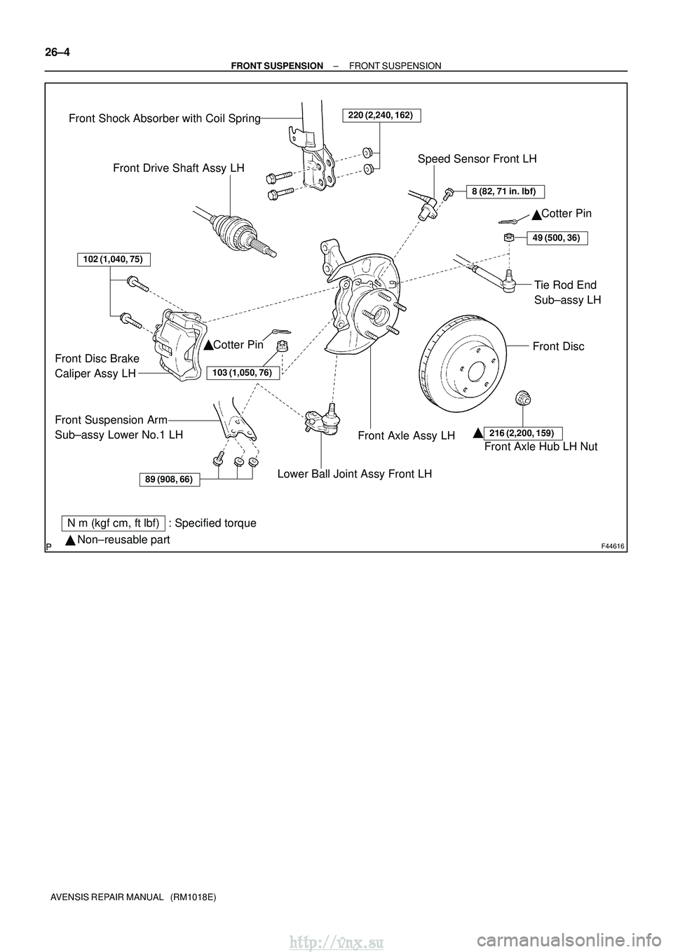
F44616
89 (908, 66)
102 (1,040, 75)
220 (2,240, 162)
8 (82, 71 in.�lbf)
49 (500, 36)
103 (1,050, 76)
216 (2,200, 159)
Front Shock Absorber with Coil Spring
Front Drive Shaft Assy LHSpeed Sensor Front LH
Cotter Pin
Front Disc
Tie Rod End
Sub±assy LH
Cotter Pin
Front Disc Brake
Caliper Assy LH
Front Suspension Arm
Sub±assy Lower No.1 LH
Lower Ball Joint Assy Front LH
Front Axle Assy LHFront Axle Hub LH Nut
N�m (kgf� cm, ft�lbf) : Specified torque
� Non±reusable part �
��
26±4
±
FRONT SUSPENSION FRONT SUSPENSION
AVENSIS REPAIR MANUAL (RM1018E)
http://vnx.su
Page 1013 of 2234

LOWER BALL JOINT ASSY FRONT LH
REPLACEMENT
HINT:
�COMPONENTS: See page 26")
260DS±01
G22708
F40228
SST
ZX1712
26±24
±
FRONT SUSPENSION LOWER BALL JOINT ASSY FRONT LH
AVENSIS REPAIR MANUAL (RM1018E)
LOWER BALL JOINT ASSY FRONT LH
REPLACEMENT
HINT:
�COMPONENTS: See page 26±2
�Replace the RH side by the same procedures as the LH side. 1. INSPECT LOWER BALL JOINT ASSY FRONT LH
(a) Jack up front side of the vehicle.
(b) Check that there is no looseness on the ball joint by shak-ing the lower arm up and down with a force of 294 N (30
kgf, 66 lbf).
2. REMOVE FRONT WHEEL
3.SEPARATE FRONT AXLE HUB LH NUT (See page 30±6) SST 09930±00010
4.DISCONNECT SPEED SENSOR FRONT LH (See page 30±6)
5.SEPARATE FRONT DISC BRAKE CALIPER ASSY LH (See page 30±22)
6. REMOVE FRONT DISC
7.SEPARATE TIE ROD END SUB±ASSY LH (See page 30±22) SST 09628±62011
8.SEPARATE FRONT SUSPENSION ARM SUB±ASSY LOWER NO.1 LH (See page 30±22)
9.REMOVE FRONT AXLE ASSY LH (See page 30±22)
10. REMOVE LOWER BALL JOINT ASSY FRONT LH
(a) Remove the cotter pin and nut.
(b) Using SST, remove the lower ball joint assy front LH.
11. INSPECT LOWER BALL JOINT ASSY FRONT LH
(a) As shown in the illustration, flip the ball joint stud back andforth 5 times, before installing the nut.
(b) Using a torque wrench, turn the nut continuously at a rate of 3 ± 5 seconds per 1 turn and take the torque reading
on the 5th turn.
Turning torque:
0.98 ± 4.9 N´m (10 ± 50 kgf´cm, 9 ± 43 in.´lbf)
http://vnx.su