Page 1243 of 1574
SECTION 9D
WIPERS/WASHER SYSTEM
Caution: Disconnect the negative battery cable before removing or installing any electrical unit or when a tool or equipment could easily come in contact with exposed electrical terminals. Disconnecting this cable will help prevent personal injury and damage to the vehicle. The ignition must also be in LOCK unless otherwisenoted.TABLE OF CONTENTS
Schematic and Routing Diagrams . . . . . . . . 9D-2 Rear Wiper and Washer . . . . . . . . . . . . . . . . . 9D-2
Maintenance and Repair . . . . . . . . . . . . . . . 9D-3 On-Vehicle Service . . . . . . . . . . . . . . . . . . . . . . 9D-3
Front Wiper and Washer . . . . . . . . . . . . . . . . 9D-3
Rear Wiper and Washer . . . . . . . . . . . . . . . . . 9D-5
Page 1250 of 1574
SECTION 9E
INSTRUMENTATION/DRIVER INFORMATION
Caution: Disconnect the negative battery cable before removing or installing any electrical unit or when a tool or equipment could easily come in contact with exposed electrical terminals. Disconnecting this cable will help prevent personal injury and damage to the vehicle. The ignition must also be in LOCK unless otherwisenoted.TABLE OF CONTENTS
Schematic and Routing Diagrams . . . . . . . . 9E-2 Cluster . . . . . . . . . . . . . . . . . . . . . . . . . . . . . . 9E-2
Component Locator . . . . . . . . . . . . . . . . . . . 9E-3 Combination Meter . . . . . . . . . . . . . . . . . . . . . 9E-3 Maintenance and Repair . . . . . . . . . . . . . . . 9E-4
On-Vehicle Service . . . . . . . . . . . . . . . . . . . . . .
9E-4
Combination Meter . . . . . . . . . . . . . . . . . . . . . 9E-4
Page 1255 of 1574
SECTION 9F
AUDIO SYSTEM
Caution: Disconnect the negative battery cable before removing or installing any electrical unit or when a tool or equipment could easily come in contact with exposed electrical terminals. Disconnecting this cable will help prevent personal injury and damage to the vehicle. The ignition must also be in LOCK unless otherwisenoted.TABLE OF CONTENTS
Schematic and Routing Diagrams . . . . . . . . 9F-2 Audio . . . . . . . . . . . . . . . . . . . . . . . . . . . . . . . 9F-2Diagnosis . . . . . . . . . . . . . . . . . . . . . . . . . . . 9F-3
General Diagnosis . . . . . . . . . . . . . . . . . . . . . 9F-3
Page 1258 of 1574

SECTION 9H
SEATS
Caution: Disconnect the negative battery cable before removing or installing any electrical unit or when a tool or equipment could easily come in contact with exposed electrical terminals. Disconnecting this cable will help prevent personal injury and damage to the vehicle. The ignition must also be in LOCK unless otherwisenoted.TABLE OF CONTENTS
Specifications . . . . . . . . . . . . . . . . . . . . . . . . 9H-1 General Specifications . . . . . . . . . . . . . . . . . . 9H-1
Diagnosis . . . . . . . . . . . . . . . . . . . . . . . . . . . 9H-2
Schematic and Routing Diagrams . . . . . . . . 9H-3 Power Seat . . . . . . . . . . . . . . . . . . . . . . . . . . . 9H-3
Seat Warmer . . . . . . . . . . . . . . . . . . . . . . . . . . 9H-4Seat Belt & Tension Reducer Circuit . . . . . . . . 9H-5
Component Locator . . . . . . . . . . . . . . . . . . . 9H-6 Front Seat & Rear Seat . . . . . . . . . . . . . . . . . 9H-6
Maintenance and Repair . . . . . . . . . . . . . . . 9H-7
On-Vehicle Service . . . . . . . . . . . . . . . . . . . . . 9H-7
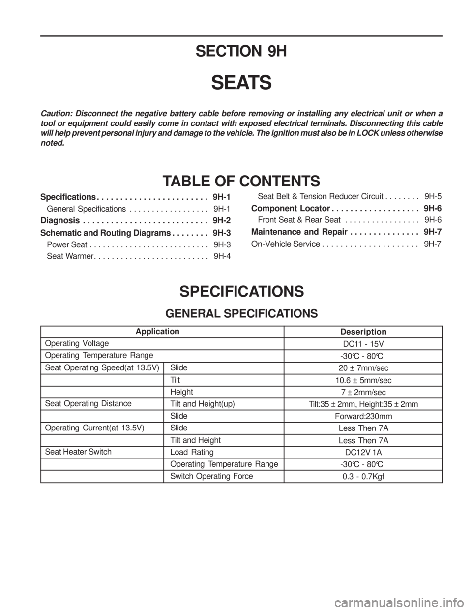
SPECIFICATIONS
GENERAL SPECIFICATIONS
Slide
Tilt Height
Tilt and Height(up)SlideSlide
Tilt and Height Load Rating
Operating Temperature RangeSwitch Operating Force
Application
Deseription
DC11 - 15V
-30°C - 80°C
20 ± 7mm/sec
10.6 ± 5mm/sec 7 ± 2mm/sec
Tilt:35 ± 2mm, Height:35 ± 2mm
Forward:230mmLess Then 7A Less Then 7A DC12V 1A
-30°C - 80°C 0.3 - 0.7Kgf
Operating Voltage
Operating Temperature Range Seat Operating Speed(at 13.5V) Seat Operating Distance Operating Current(at 13.5V) Seat Heater Switch
Page 1267 of 1574
SECTION 9L
GLASS AND MIRRORS
Caution: Disconnect the negative battery cable before removing or installing any electrical unit or when a tool or equipment could easily come in contact with exposed electrical terminals. Disconnecting this cable will help prevent personal injury and damage to the vehicle. The ignition must also be in LOCK unless otherwisenoted.TABLE OF CONTENTS
Schematic and Routing Diagrams . . . . . . . . 9L-2 Outside Mirror . . . . . . . . . . . . . . . . . . . . . . . . . 9L-2
Auto Dimming Room Mirror . . . . . . . . . . . . . . . 9L-3
Maintenance and Repair . . . . . . . . . . . . . . . 9L-4 On-Vehicle Service . . . . . . . . . . . . . . . . . . . . . .
9L-4
Front & Side Glass . . . . . . . . . . . . . . . . . . . . . 9L-4
Tailgate Glass . . . . . . . . . . . . . . . . . . . . . . . . . 9L-9
Auto Dimming Room Mirror . . . . . . . . . . . . . . 9L-12
Page 1289 of 1574
SECTION 9P
DOORS
Caution: Disconnect the negative battery cable before removing or installing any electrical unit or when a tool or equipment could easily come in contact with exposed electrical terminals. Disconnecting this cable will help prevent personal injury and damage to the vehicle. The ignition must also be in LOCK unless otherwisenoted.TABLE OF CONTENTS
Schematic and Routing Diagrams . . . . . . . . 9P-2 Power Window . . . . . . . . . . . . . . . . . . . . . . . . 9P-2
Maintenance and Repair . . . . . . . . . . . . . . . 9P-3
On-Vehicle Service . . . . . . . . . . . . . . . . . . . . . . 9P-3Front Door . . . . . . . . . . . . . . . . . . . . . . . . . . . 9P-3
Rear Door . . . . . . . . . . . . . . . . . . . . . . . . . . . . 9P-4
Tail Gate . . . . . . . . . . . . . . . . . . . . . . . . . . . . . 9P-5
Page 1305 of 1574

SECTION 9T
REMOTE KEYLESS ENTRY ANDANTI-THEFT SYSTEM
Caution: Disconnect the negative battery cable before removing or installing any electrical unit or when a tool or equipment could easily come in contact with exposed electrical terminals. Disconnecting this cablewill help prevent personal injury and damage to the vehicle. The ignition must also be in LOCK unless otherwisenoted.
TABLE OF CONTENTS
Specifications . . . . . . . . . . . . . . . . . . . . . . . . 9T-1
REKES Specifications . . . . . . . . . . . . . . . . . . . 9T-1
Schematic and Routing Diagrams . . . . . . . . 9T-2
REKES . . . . . . . . . . . . . . . . . . . . . . . . . . . . . . 9T-2
Diagnosis . . . . . . . . . . . . . . . . . . . . . . . . . . . 9T-3
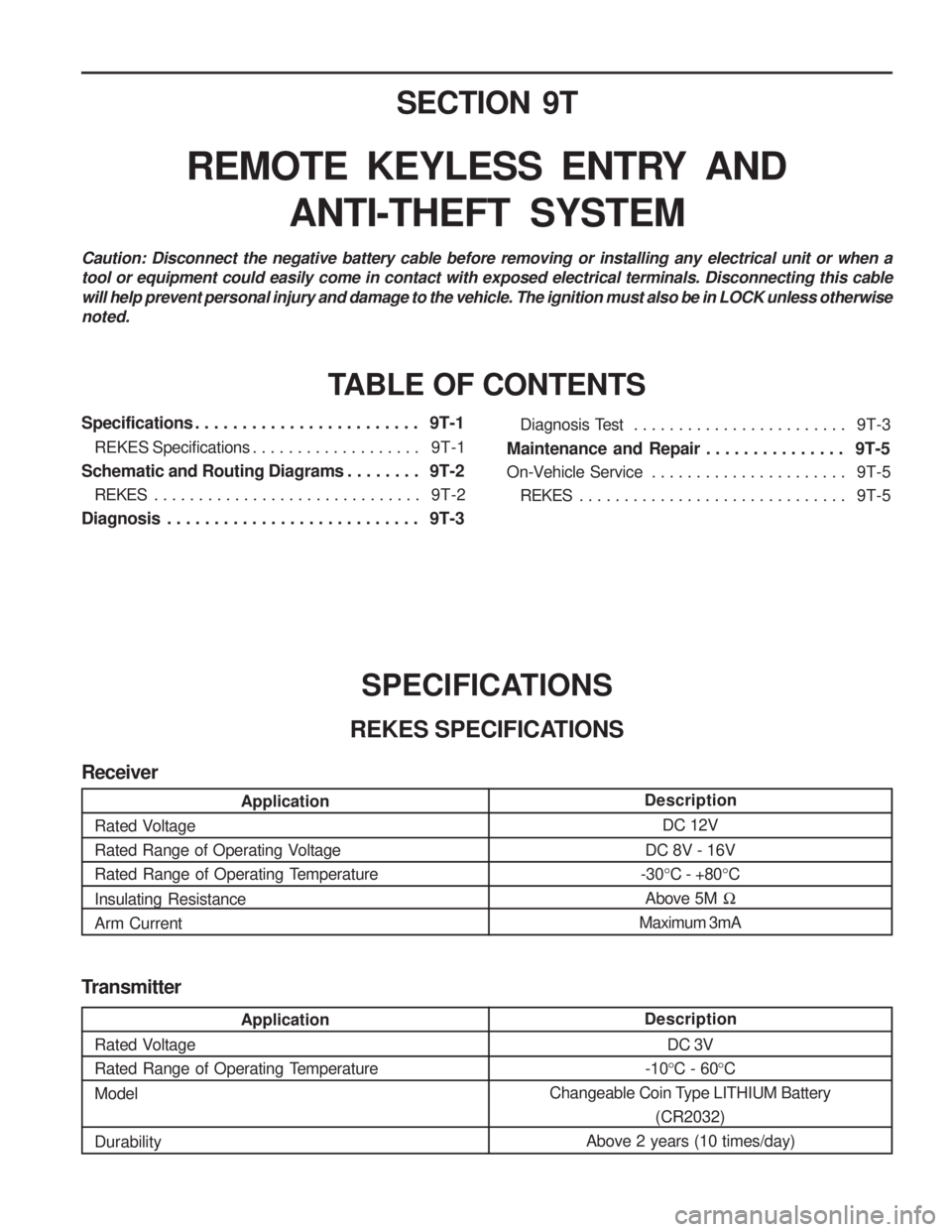
SPECIFICATIONS
REKES SPECIFICATIONS Diagnosis Test . . . . . . . . . . . . . . . . . . . . . . . .
9T-3
Maintenance and Repair . . . . . . . . . . . . . . . 9T-5
On-Vehicle Service . . . . . . . . . . . . . . . . . . . . . . 9T-5
REKES . . . . . . . . . . . . . . . . . . . . . . . . . . . . . . 9T-5
Transmitter
Description DC 3V
-10 °C - 60 °C
Changeable Coin Type LITHIUM Battery (CR2032)
Above 2 years (10 times/day)
Application
Rated Voltage
Rated Range of Operating Temperature Model Durability
Description DC 12V
DC 8V - 16V
-30 °C - +80 °C
Above 5M �
Maximum 3mA
Application
Rated Voltage
Rated Range of Operating Voltage
Rated Range of Operating Temperature Insulating Resistance Arm Current
Receiver
Page 1317 of 1574

MUSSO-SPORTS 1A-5
SUPPLEMENT
KAA5A020
KAA5A020
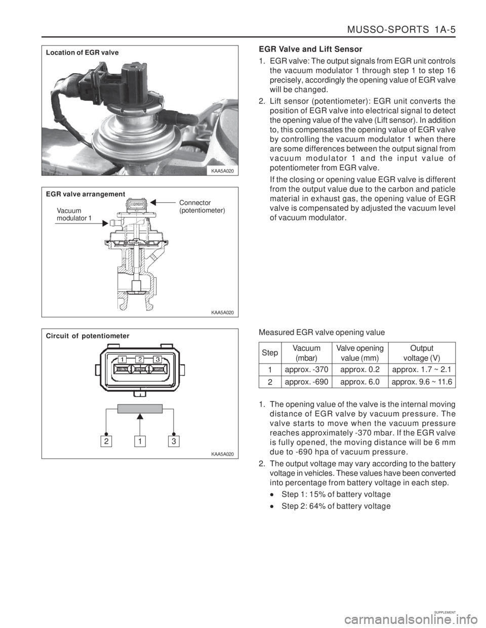
KAA5A020EGR Valve and Lift Sensor
1. EGR valve: The output signals from EGR unit controls
the vacuum modulator 1 through step 1 to step 16 precisely, accordingly the opening value of EGR valvewill be changed.
2. Lift sensor (potentiometer): EGR unit converts the position of EGR valve into electrical signal to detectthe opening value of the valve (Lift sensor). In additionto, this compensates the opening value of EGR valveby controlling the vacuum modulator 1 when thereare some differences between the output signal fromvacuum modulator 1 and the input value ofpotentiometer from EGR valve. If the closing or opening value EGR valve is different from the output value due to the carbon and paticlematerial in exhaust gas, the opening value of EGRvalve is compensated by adjusted the vacuum levelof vacuum modulator.
Measured EGR valve opening value Step 1 2
Vacuum(mbar)
approx. -370 approx. -690 Valve opening
value (mm)
approx. 0.2approx. 6.0 Output
voltage (V)
approx. 1.7 ~ 2.1
approx. 9.6 ~ 11.6
1. The opening value of the valve is the internal moving distance of EGR valve by vacuum pressure. The valve starts to move when the vacuum pressurereaches approximately -370 mbar. If the EGR valveis fully opened, the moving distance will be 6 mmdue to -690 hpa of vacuum pressure.
2. The output voltage may vary according to the battery voltage in vehicles. These values have been convertedinto percentage from battery voltage in each step.
Step 1: 15% of battery voltage
Step 2: 64% of battery voltage
Location of EGR valve EGR valve arrangement
Vacuum modulator 1 Connector (potentiometer)
Circuit of potentiometer
312