2003 SSANGYONG MUSSO fuel pressure
[x] Cancel search: fuel pressurePage 902 of 1574

AUTOMATIC TRANSMISSION 5A-43
Figure 4.1 - Power Flow Diagram TORQUE CONVERTER
The torque converter (refer figure 4.2) consists of a turbine,
stator pump, impeller and a lock-up damper and piston
assembly. As in conventional torque converters, the impeller is
attached to the converter cover, the turbine is splined to the
input shaft and the stator is mounted on the pump housing via
a one way clutch (sprag).
The addition of the damper and piston assembly enables the
torque converter to ‘lock-up’ under favourable conditions. Lock-
up is only permitted to occur in third and fourth gears under
specified throttle and road speed conditions.
Lock-up is achieved by applying hydraulic pressure to the
damper and piston assembly which couples the turbine to the
converter cover, locking-up the converter and eliminating
unwanted slippage. Whenever lock-up occurs, improved fuel
consumption is achieved. Torsional damper springs are
provided in the damper and piston assembly to absorb anyengine torque fluctuations during lock-up. Figure 4.2 - Torque Converter Cross Section
Page 1148 of 1574
6A-6 POWER STEERING SYSTEM
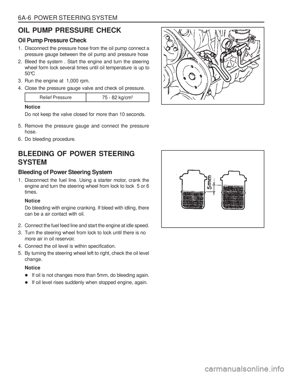
OIL PUMP PRESSURE CHECK Oil Pump Pressure Check
1. Disconnect the pressure hose from the oil pump connect apressure gauge between the oil pump and pressure hose
2. Bleed the system . Start the engine and turn the steering wheel form lock several times until oil temperature is up to
50°C
3. Run the engine at 1,000 rpm.
4. Close the pressure gauge valve and check oil pressure.
NoticeDo not keep the valve closed for more than 10 seconds.
5. Remove the pressure gauge and connect the pressure hose.
6. Do bleeding procedure. BLEEDING OF POWER STEERING SYSTEM Bleeding of Power Steering System
1. Disconnect the fuel line. Using a starter motor, crank the engine and turn the steering wheel from lock to lock 5 or 6 times. Notice Do bleeding with engine cranking. If bleed with idling, there can be a air contact with oil.
2. Connect the fuel feed line and start the engine at idle speed.
3. Turn the steering wheel from lock to lock until there is no more air in oil reservoir.
4. Connect the oil level is within specification.
5. By turning the steering wheel left to right, check the oil level change. Notice
� If oil is not changes more than 5mm, do bleeding again.
� If oil level rises suddenly when stopped engine, again.
Relief Pressure
75 - 82 kg/cm2
Page 1252 of 1574
INSTRUMENTATION/DRIVER INFORMATION 9E-3
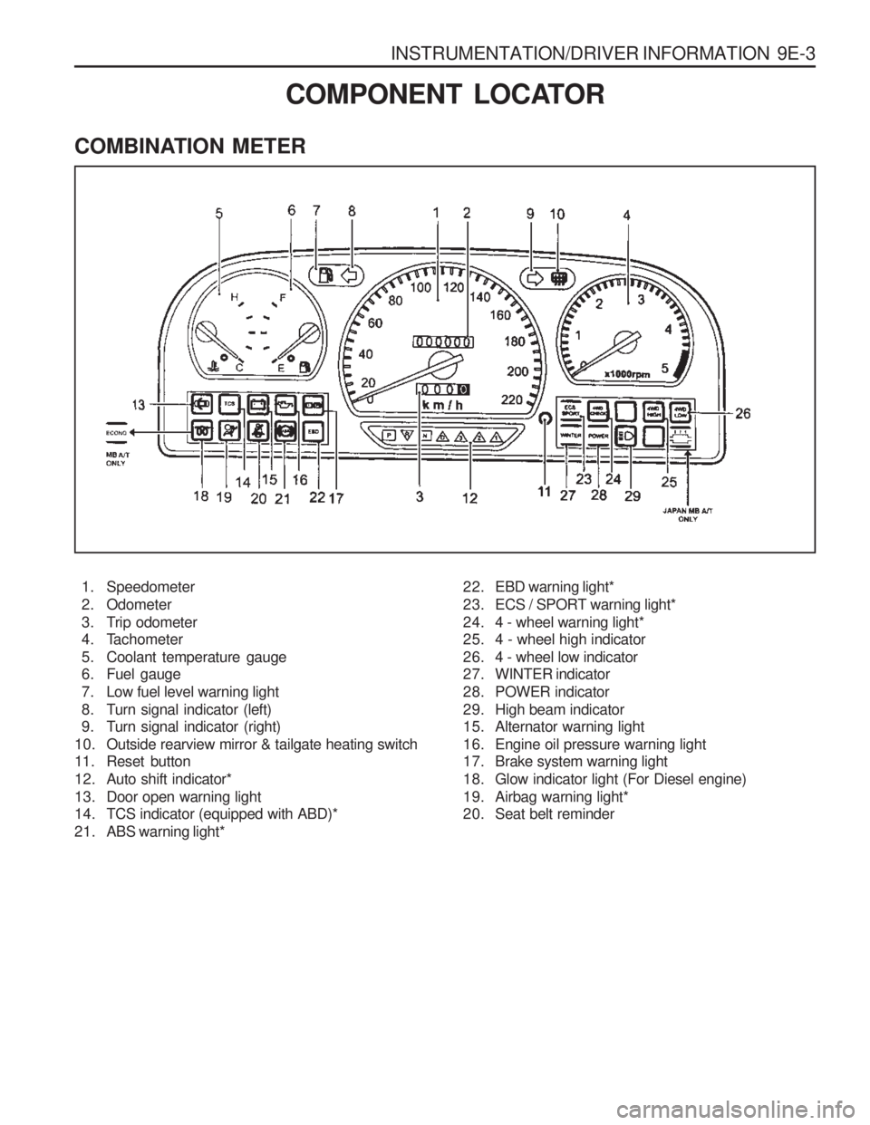
COMBINATION METER
COMPONENT LOCATOR
1. Speedometer
2. Odometer
3. Trip odometer
4. Tachometer
5. Coolant temperature gauge
6. Fuel gauge
7. Low fuel level warning light
8. Turn signal indicator (left)
9. Turn signal indicator (right)
10. Outside rearview mirror & tailgate heating switch
11. Reset button
12. Auto shift indicator*
13. Door open warning light
14. TCS indicator (equipped with ABD)*
21. ABS warning light* 22. EBD warning light*
23. ECS / SPORT warning light*
24. 4 - wheel warning light*
25. 4 - wheel high indicator
26. 4 - wheel low indicator
27. WINTER indicator
28. POWER indicator
29. High beam indicator
15. Alternator warning light
16. Engine oil pressure warning light
17. Brake system warning light
18. Glow indicator light (For Diesel engine)
19. Airbag warning light*
20. Seat belt reminder
Page 1315 of 1574
MUSSO-SPORTS 1A-3
SUPPLEMENT
HUBER EGR
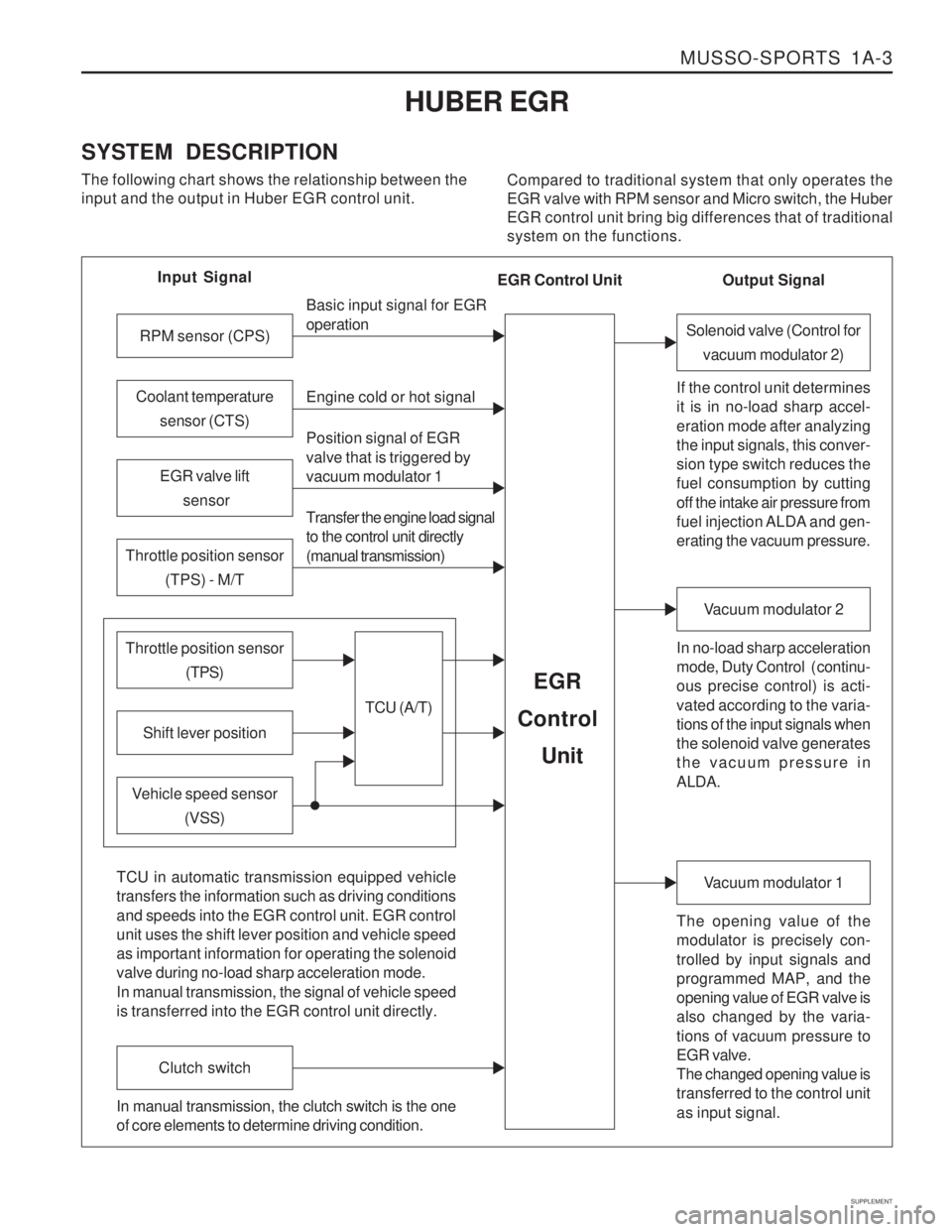
SYSTEM DESCRIPTION The following chart shows the relationship between the input and the output in Huber EGR control unit. Compared to traditional system that only operates theEGR valve with RPM sensor and Micro switch, the HuberEGR control unit bring big differences that of traditionalsystem on the functions.
Input Signal
RPM sensor (CPS)
EGR valve lift sensor
Throttle position sensor (TPS) - M/T
Shift lever position
Throttle position sensor (TPS)
Vehicle speed sensor(VSS) Basic input signal for EGR operation Engine cold or hot signal
Position signal of EGR valve that is triggered by vacuum modulator 1 Transfer the engine load signal to the control unit directly (manual transmission)
TCU (A/T)
EGR
Control
Unit
Coolant temperature sensor (CTS)
Solenoid valve (Control forvacuum modulator 2)
If the control unit determines it is in no-load sharp accel- eration mode after analyzing the input signals, this conver- sion type switch reduces the fuel consumption by cutting off the intake air pressure from
fuel injection ALDA and gen- erating the vacuum pressure. In no-load sharp acceleration
mode, Duty Control ( continu- ous precise control) is acti- vated according to the varia- tions of the input signals when the solenoid valve generates the vacuum pressure in ALDA.
Vacuum modulator 2
The opening value of the modulator is precisely con- trolled by input signals and programmed MAP, and the opening value of EGR valve is also changed by the varia- tions of vacuum pressure to EGR valve. The changed opening value is transferred to the control unit as input signal.
Vacuum modulator 1
TCU in automatic transmission equipped vehicle transfers the information such as driving conditions and speeds into the EGR control unit. EGR control unit uses the shift lever position and vehicle speed as important information for operating the solenoid valve during no-load sharp acceleration mode. In manual transmission, the signal of vehicle speed is transferred into the EGR control unit directly.
Clutch switch
In manual transmission, the clutch switch is the one of core elements to determine driving condition. Output Signal
EGR Control Unit
Page 1322 of 1574
1A-10 MUSSO-SPORTS
SUPPLEMENT
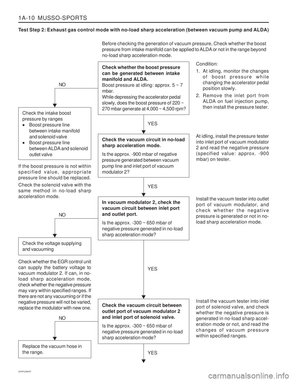
Test Step 2: Exhaust gas control mode with no-load sharp acceleration (between vacuum pump and ALDA)
Condition:
1. At idling, monitor the changesof boost pressure while changing the accelerator pedalposition slowly.
2. Remove the inlet port from ALDA on fuel injection pump,then install the pressure tester.
Before checking the generation of vacuum pressure, Check whether the boost
pressure from intake manifold can be applied to ALDA or not in the range beyond no-load sharp acceleration mode. Check whether the boost pressure can be generated between intake manifold and ALDA. Boost pressure at idling: approx. 5 ~ 7 mbar. While depressing the accelerator pedal slowly, does the boost pressure of 220 ~ 270 mbar generate at 4,000 ~ 4,500 rpm?
At idling, install the pressure tester into inlet port of vacuum modulator2 and read the negative pressure(specified value: approx. -900mbar) on tester. Install the vacuum tester into inlet port of solenoid valve, and checkwhether the negative pressure isgenerated in no-load sharp accel-eration mode or not, and read thechanges of vacuum pressurewithin specified ranges.
NO
If the boost pressure is not within specified value, appropriatepressure line should be replaced. Check the solenoid valve with the same method in no-load sharpacceleration mode.
YES
YES
Check the vacuum circuit in no-load sharp acceleration mode. Is the approx. -900 mbar of negative pressure generated between vacuum pump line and inlet port of vacuum modulator 2?
In vacuum modulator 2, check the vacuum circuit between inlet port and outlet port. Is the approx. -300 ~ 650 mbar of negative pressure generated in no-load sharp acceleration mode?
Check the vacuum circuit between outlet port of vacuum modulator 2 and inlet port of solenoid valve. Is the approx. -300 ~ 650 mbar of negative pressure generated in no-load sharp acceleration mode?
Install the vacuum tester into outlet port of vacuum modulator, andcheck whether the negativepressure is generated or not in no-load sharp acceleration mode.
Check the intake boost pressure by ranges
Boost pressure line
between intake manifold and solenoid valve
Boost pressure line
between ALDA and solenoid outlet valve
NO
Check the voltage supplying and vacuuming
Check whether the EGR control unit can supply the battery voltage tovacuum modulator 2. If can, in no-load sharp acceleration mode,check whether the negative pressuremay vary within specified ranges. Ifthere are not any vacuuming or if thenegative pressure will not be varied,replace the modulator with new one. YES
YES
NO
Replace the vacuum hose in the range.
Page 1373 of 1574
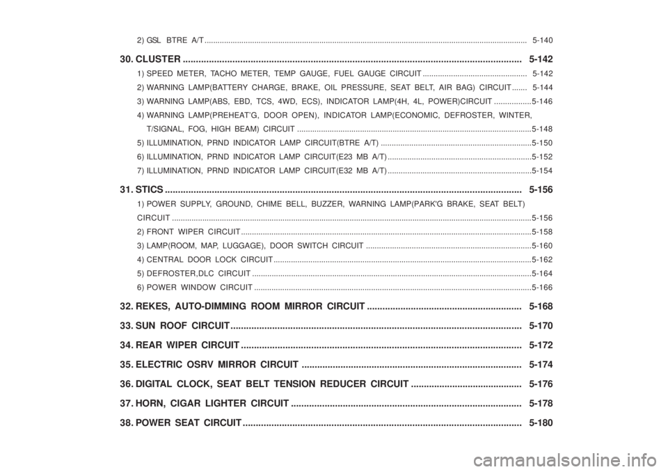
2 ) GSL BTRE A/T ..................................................................................................................................................... 5-140
30. CLUSTER ............................................................................................................................... ... 5-142
1) SPEED METER, TACHO METER, TEMP GAUGE, FUEL GAUGE CIRCUIT ................................................ 5-142
2) WARNING LAMP(BA TTERY CHARGE, BRAKE, OIL PRESSURE, SEAT BELT, AIR BAG) CIRCUIT ....... 5-144
3) WARNING LAMP(ABS, EBD, TCS, 4WD, ECS), INDICATOR LAMP(4H, 4L, POWER)CIRCUIT ................. 5-146
4) WARNING LAMP(PREHEA T’G, DOOR OPEN), INDICATOR LAMP(ECONOMIC, DEFROSTER, WINTER,
T/SIGNAL, FOG, HIGH BEAM) CIRCUIT .............................................................................................. ..............5-148
5) ILLUMINATION, PRND INDICATOR LAMP CIRCUIT(BTRE A/T) ..................................................................... 5-150
6) ILLUMINATION, PRND INDICATOR LAMP CIRCUIT(E23 MB A/T) .................................................................. 5-152
7) ILLUMINATION, PRND INDICATOR LAMP CIRCUIT(E32 MB A/T) .................................................................. 5-154
31. STICS ....................................................................................................................... .................. 5-156
1) POWER SUPPLY, GROUND, CHIME BELL, BUZZER, WARNING LAMP(PARK'G BRAKE, SEAT BELT)
CIRCUIT ...................................................................................................................................................................... 5-156
2) FRONT WIPER CIRCUIT ...................................................................................................................................... 5-158
3) LAMP(ROOM, MAP, LUGGAGE), DOOR SWITCH CIRCUIT ............................................................................ 5-160
4) CENTRAL DOOR LOCK CIRCUIT ....................................................................................................................... 5-162
5) DEFROSTER,DLC CIRCUIT ............................................................................................................................... ..5-164
6) POWER WINDOW CIRCUIT ............................................................................................................................... .5-166
32. REKES, AUTO-DIMMING ROOM MIRROR CIRCUIT ............................................................ 5-168
33. SUN ROOF CIRCUIT ............................................................................................................ .... 5-170
34. REAR WIPER CIRCUIT .......................................................................................................... .. 5-172
35. ELECTRIC OSRV MIRROR CIRCUIT ..................................................................................... 5-174
36. DIGITAL CLOCK, SEAT BELT TENSION REDUCER CIRCUIT ........................................... 5-176
37. HORN, CIGAR LIGHTER CIRCUIT ......................................................................................... 5-178
38. POWER SEAT CIRCUIT ........................................................................................................... 5-180