2003 SSANGYONG MUSSO clutch
[x] Cancel search: clutchPage 890 of 1574
AUTOMATIC TRANSMISSION 5A-31
K-Line
The K-line is typically used for obtaining diagnostic information from the TCU. A computer with a special interface is
connected to the TCU and all current faults, stored faults, runtime parameters are then available. The stored faultcodes can also be cleared.
The K-line can be used for vehicle coding at the manufacturer’ s plant or in the workshop. This allows for one TCU
design to be used over different vehicle models. The particular code is sent to the microprocessor via the K line and
this results in the software selecting the correct shift and VPS ramp parameters. HYDRAULIC CONTROL SYSTEM
The hydraulic controls are located in the valve body, pump body and main case.The valve body contains the following:
� Manual valve,
� Three shift valves,
� Sequence valve,
� solenoid supply pressure regulator valve,
� line pressure control valve,
� clutch apply regulator valve,
� band apply regulator valve,
� S1 to S6, and
� Reverse lockout valve.
� The pump body contains the following:
� Primary regulator valve for line pressure,
� converter clutch regulator valve,
� converter clutch control valve,
� S7,and
� C1 bias valve.
The main case contains the following:
� B1R exhaust valve
The hydraulic control system schematic is shown at figure 3.7.
All upshifts are accomplished by simultaneously switching on a shift valve(s), switching VPS pressure to the band
and/or clutch regulator valve, and then sending the VPS a ramped current. The shift is completed by switching the
regulators off and at the same time causing the VPS to reach maximum . pressure. All downshifts are accomplished
by switching VPS pressure to the band and/or clutch regulator valve and sending a ramped current to the VPS. The
shift is completed by simultaneously switching the regulators off, switching the shift valves and at the same timecausing the VPS to return to stand-by pressure.
The primary regulator valve is located in the pump cover and supplies four line pressures; high and low for forward
gears, and high and low for reverse. This pressure has no effect on shift quality and merely provides static clutch
capacity during steady state operation. Low pressure can be obtained by activating an On/off solenoid with high line pressure being the default mode.
Torque converter lock-up is initiated by toggling the converter clutch control valve with an On/off solenoid. The actual apply and release of the clutch is regulated by the VPS via the converter clutch regulator valve. As an additionalsafety feature, the lock-up is hydraulically disabled in first and second gear by the bias valve which only supplies oilto the lock-up solenoid when C1 is applied in third and fourth gears. This prevents the vehicle from being renderedimmobile in the unlikely event of S7 becoming stuck.
The solenoid supply valve provides reference pressure for all the solenoids.
Page 893 of 1574
5A-34 AUTOMATIC TRANSMISSION
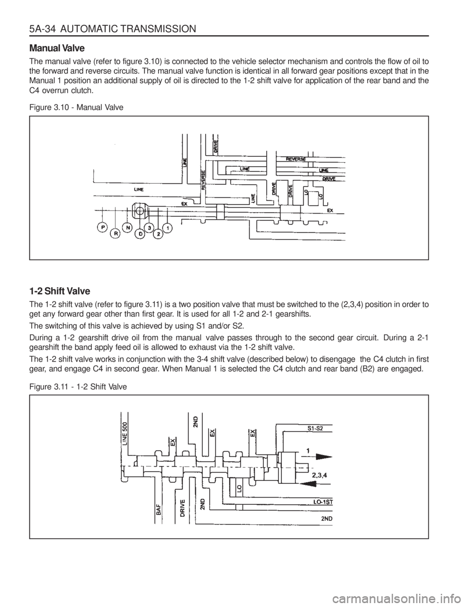
Figure 3.10 - Manual Valve
1-2 Shift Valve
The 1-2 shift valve (refer to figure 3.11) is a two position valve that must be switched to the (2,3,4) position in order to
get any forward gear other than first gear. It is used for all 1-2 and 2-1 gearshifts.
The switching of this valve is achieved by using S1 and/or S2.
During a 1-2 gearshift drive oil from the manual valve passes through to the second gear circuit. During a 2-1
gearshift the band apply feed oil is allowed to exhaust via the 1-2 shift valve.
The 1-2 shift valve works in conjunction with the 3-4 shift valve (described below) to disengage the C4 clutch in first
gear, and engage C4 in second gear. When Manual 1 is selected the C4 clutch and rear band (B2) are engaged.
Figure 3.11 - 1-2 Shift Valve
Manual Valve The manual valve (refer to figure 3.10) is connected to the vehicle selector mechanism and controls the flow of oil to the forward and reverse circuits. The manual valve function is identical in all forward gear positions except that in theManual 1 position an additional supply of oil is directed to the 1-2 shift valve for application of the rear band and the C4 overrun clutch.
Page 894 of 1574
AUTOMATIC TRANSMISSION 5A-35
2-3 Shift Valve
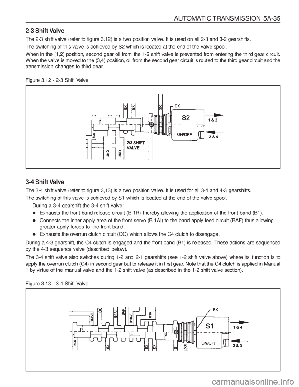
The 2-3 shift valve (refer to figure 3.12) is a two position valve. It is used on all 2-3 and 3-2 gearshifts.
The switching of this valve is achieved by S2 which is located at the end of the valve spool.
When in the (1,2) position, second gear oil from the 1-2 shift valve is prevented from entering the third gear circuit.
When the valve is moved to the (3,4) position, oil from the second gear circuit is routed to the third gear circuit and the
transmission changes to third gear.
Figure 3.12 - 2-3 Shift Valve
3-4 Shift Valve
The 3-4 shift valve (refer to figure 3,13) is a two position valve. It is used for all 3-4 and 4-3 gearshifts.
The switching of this valve is achieved by S1 which is located at the end of the valve spool.During a 3-4 gearshift the 3-4 shift valve:
� Exhausts the front band release circuit (B 1R) thereby allowing the application of the front band (B1).
� Connects the inner apply area of the front servo (B 1AI) to the band apply feed circuit (BAF) thus allowing
greater apply forces to the front band.
� Exhausts the overrun clutch circuit (OC) which allows the C4 clutch to disengage.
During a 4-3 gearshift, the C4 clutch is engaged and the front band (B1) is released. These actions are sequenced
by the 4-3 sequence valve (described below).
The 3-4 shift valve also switches during 1-2 and 2-1 gearshifts (see 1-2 shift valve above) where its function is to
apply the overrun clutch (C4) in second gear but to release it in first gear. Note that the C4 clutch is applied in Manual
1 by virtue of the manual valve and the 1-2 shift valve (as described in the 1-2 shift valve section).
Figure 3.13 - 3-4 Shift Valve
Page 895 of 1574
5A-36 AUTOMATIC TRANSMISSION
4-3 Sequence Valve
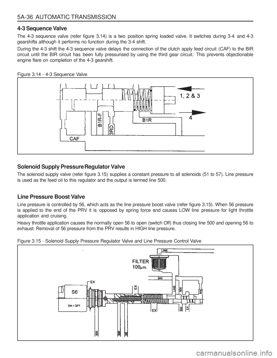
The 4-3 sequence valve (refer figure 3.14) is a two position spring loaded valve. It switches during 3-4 and 4-3
gearshifts although it performs no function during the 3-4 shift.
During the 4-3 shift the 4-3 sequence valve delays the connection of the clutch apply feed circuit (CAF) to the BIR
circuit until the BIR circuit has been fully pressurised by using the third gear circuit. This prevents objectionable
engine flare on completion of the 4-3 gearshift.
Figure 3.14 - 4-3 Sequence Valve
Figure 3.15 - Solenoid Supply Pressure Regulator Valve and Line Pressure Control Valve
Solenoid Supply Pressure Regulator Valve
The solenoid supply valve (refer figure 3.15) supplies a constant pressure to all solenoids (51 to 57). Line pressure
is used as the feed oil to this regulator and the output is termed line 500.
Line Pressure Boost Valve
Line pressure is controlled by 56, which acts as the line pressure boost valve (refer figure 3.15). When 56 pressure
is applied to the end of the PRV it is opposed by spring force and causes LOW line pressure for light throttleapplication and cruising.
Heavy throttle application causes the normally open 56 to open (switch Off) thus closing line 500 and opening 56 to
exhaust. Removal of 56 pressure from the PRV results in HIGH line pressure.
Page 896 of 1574
AUTOMATIC TRANSMISSION 5A-37
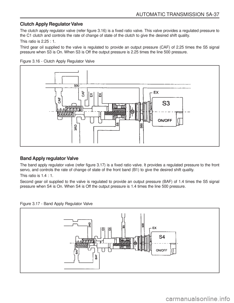
Figure 3.16 - Clutch Apply Regulator Valve
Clutch Apply Regulator Valve
The clutch apply regulator valve (refer figure 3.16) is a fixed ratio valve. This valve provides a regulated pressure to
the C1 clutch and controls the rate of change of state of the clutch to give the desired shift quality. This ratio is 2.25 : 1.
Third gear oil supplied to the valve is regulated to provide an output pressure (CAF) of 2.25 times the S5 signal
pressure when S3 is On. When S3 is Off the output pressure is 2.25 times the line 500 pressure.
Band Apply regulator Valve The band apply regulator valve (refer figure 3.17) is a fixed ratio valve. It provides a regulated pressure to the front
servo, and controls the rate of change of state of the front band (B1) to give the desired shift quality. This ratio is 1.4 : 1.
Second gear oil supplied to the valve is regulated to provide an output pressure (BAF) of 1.4 times the S5 signal pressure when S4 is On. When S4 is Off the output pressure is 1.4 times the line 500 pressure.
Figure 3.17 - Band Apply Regulator Valve
Page 898 of 1574

AUTOMATIC TRANSMISSION 5A-39
Primary Regulator Valve
The primary regulator valve (PRV) (refer to figure 3.19) regulates the transmission line pressure (or pump output
pressure). This valve gives either high or low line pressure depending on whether S6 is switched Off or On, When S6
is switched On,S6 pressure is applied to the PRV moving it against spring pressure and opening the line pressure
circuit to the pump suction port resulting in reduced line pressure. Low line pressure is used during light throttle
applications and cruising. Heavy throttle will cause S6 to switch Off and thereby cause high line pressure.
This stepped line pressure control has no detrimental effect on shift feel because all shifting pressures are controlled
by separate band and clutch regulator valves, and the output of S5.
When reverse gear is selected, both the low and high line pressure values are boosted to guard against slippage.
This is achieved by applying reverse oil line pressure to the PRV to assist the spring load. The other end of the valvecontains ports for line pressure feedback and 56 pressure.
The PRV also regulates the supply of oil to the converter via the converter feed port. The cascade effect of the PRV
ensures the first priority of the valve is to maintain line pressure at very low engine speeds. When the engine speed
increases and the pump supplies an excess of oil the PRV moves to uncover the converter feed port thereby pressurising
the converter. If there is an excess of oil for the transmission’s needs then the PRV moves further to allow oil to return
to the suction port.
Figure 3.19 - Primary Regulator Valve
Page 899 of 1574

5A-40 AUTOMATIC TRANSMISSION
Converter Clutch Regulator Valve
The converter clutch regulator valve (refer figure 3.20) regulates
the pressure of the oil which applies the converter clutch. Input
oil from the line 500 circuit is regulated within the valve, with the output pressure being variable according to the signal
pressure from the S5 circuit. Converter clutch apply and release
application is smoothed by electronically varying the S5 circuitpressure.
Converter Clutch Control Valve
The converter clutch control valve (refer figure 3.21) is a two position valve which applies or releases the converter clutch.
The switching of this valve is governed by the signal pressure from S7.
When the valve is in the off or released position, converter feed oil from the PRV is directed to the release side of the
converter clutch. After flowing through the converter, oil returns to the converter clutch control valve and is then
directed to the oil cooler.
When the valve is in the on or applied position, regulated oil from the converter clutch regulator valve is directed to
the apply side of the converter clutch. This oil remains within the converter because the converter clutch piston is
sealed against the flat friction surface of the converter cover. To provide oil flow to the cooler the converter clutch
control valve directs converter feed oil from the PRV directly to the cooler circuit.
Figure 3.21- Converter Clutch Control Valve Figure 3.20 - Converter Clutch Regulator Valve
Page 900 of 1574

AUTOMATIC TRANSMISSION 5A-41
C1 Bias Valve
The C1 bias valve (refer figure 3.22) ensures that the converter lock-up clutch is only applied in third and fourth
gears. It uses C1 clutch oil pressure as the switching signal since C1 is only applied in third and fourth gears.
Line to 500 oil is routed through the C1 bias valve to S7. The C1 bias valve therefore acts as a safety feature to
ensure drivability in the event of S7 failure.
Figure 3.22- C1 Bias Valve
B1R Exhaust Valve The B1R exhaust valve (refer figure 3.23) is a two position spring loaded valve located in the transmission case directly
adjacent to the front servo. It permits the servo release oil to be rapidly exhausted into the transmission case during
application of the front band (B1). This prevents the need to
force the oil back from the front servo through the valve body
and through the 3-4 shift valve. The spring positions the valve
to prevent oil entering the release area of the servo until the
B1R circuit oil pressure reaches approximately 100 kPa.
Figure 3.23 - B1R Exhaust Valve