Page 290 of 1574
OM600 ENGINE MECHANICAL 1B3-25
6. Pull off the tensioning lever (4) from guide rail pin.
7. Remove the spring (17).Installation NoticeInsert spring (17) with color coding (blue/violet) facing up.
8. Pry off the closing cover (12) and remove the socket bolt(11) and then remove the tensioning pulley (10). Installation Notice
Tightening Torque 29 Nm
9. Pry off the closing cover (16) and remove the fit bolt (15).
10. Remove the tensioning lever (14) and washer (13).
11. Clean thread in the timing case cover and fit bolt.
Installation Notice Apply Loctite on thread of fit bolt.
Tightening Torque 100 Nm
12. Installation should follow the removal procedure in the reverse order.
Page 296 of 1574
OM600 ENGINE MECHANICAL 1B3-31
Assembly ProcedureNotice In case the prechambers are reused, inspect the
prechambers thoroughly, if the ball pin by heat and fire is broken, it can not be used.
1. Clean the sealing surface of the prechamber.
2. Insert the prechamber into the cylinder head at the same time aligning the cam on the collar of the prechambers with the slots in the cylinder head. Notice If the spacer rings are fitted to the prechambers, the spacer rings should be replaced with rings of the same thickness.
Thickness of Spacer Ring 0.3, 0.6, 1.0 mm
3. Coat the threaded ring with oil and assemble the ring by using the serration wrench.
Tightening Torque 130 Nm
Page 297 of 1574
1B3-32 OM600 ENGINE MECHANICAL
MILLING OF PRECHAMBER SEALING SURFACE1 Drift
2 Sleeve
3 Milling Cutter 4 Counter Sink (Special Tool - 601 589 00 66)
5 Cylinder Head
Tightening Torque 0.3, 0.6, 1.0 mm
Milling of the Prechamber Sealing Surface
Notice The prechamber sealing surface may only be remachined once with the cylinder head fitted. It is essential to adhere to the specified projection ‘C’ of the prechamber of 7.6 -
8.1mm. This ensures that the required clearance exists between prechamber and piston crown with the piston in TDC. Forthis reason, spacer rings should be inserted on remachinedsealing surfaces. If a spacer ring is already fitted, or a marking is made on the cylinder head, the cylinder head must be removed and size
‘C’ measured if further remachining is necessary on a
prechamber sealing surface.
Tools Required 601 589 00 66 00 Counter Sink 667 589 00 23 00 Height Gauge
Page 301 of 1574

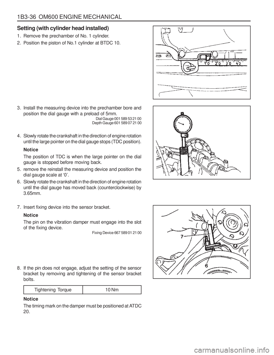
1B3-36 OM600 ENGINE MECHANICAL Setting (with cylinder head installed)
1. Remove the prechamber of No. 1 cylinder.
2. Position the piston of No.1 cylinder at BTDC 10.
3. Install the measuring device into the prechamber bore andposition the dial gauge with a preload of 5mm. Dial Gauge 001 589 53 21 00
Depth Gauge 601 589 07 21 00
4. Slowly rotate the crankshaft in the direction of engine rotation until the large pointer on the dial gauge stops (TDC position). Notice The position of TDC is when the large pointer on the dial gauge is stopped before moving back.
5. remove the reinstall the measuring device and position the dial gauge scale at ‘0’.
6. Slowly rotate the crankshaft in the direction of engine rotation until the dial gauge has moved back (counterclockwise) by3.65mm.
7. Insert fixing device into the sensor bracket. Notice The pin on the vibration damper must engage into the slot of the fixing device. Fixing Device 667 589 01 21 00
8. If the pin does not engage, adjust the setting of the sensor bracket by removing and tightening of the sensor bracketbolts.
Tightening Torque 10 Nm
Notice
The timing mark on the damper must be positioned at ATDC 20.
Page 303 of 1574
1B3-38 OM600 ENGINE MECHANICAL
000 589 77 03 00 Box Wrench Insert
001 589 65 09 00 Socket Wrench Insert
102 589 03 40 00 Magnetic Bar
116 589 02 34 00 Threaded Pin
116 589 03 07 00 T Type Socket Wrench
116 589 20 33 00 Sliding Hammer
601 589 00 10 00 Cylinder Head Bolt Wrench
602 589 00 40 00 Engine Lock
603 589 00 40 00 Counter Holder
Tools Required
Cylinder Bolts (12-sided socket head) (Engine cold) M8 Cylinder Head Bolts
Tightening Torque
stage1 stage2stage3
10 Nm35 Nm
180 °
25 Nm
Tightening Sequence for Cylinder Head Bolts OM 662LA Engine
OM 661LA Engine
Page 304 of 1574
OM600 ENGINE MECHANICAL 1B3-39
Length(L) When New80mm
102mm 115mm
Thread Dia.
M10 M10M10Max. Length(L) 82mm
104mm 117mm
The twelve-sided socket head bolts are tightened with each stages of torque and torque angle. It is not necessary to retighten the cylinder head bolts at the 1000~1500km inspection or after 1000~1500km of repairs.
Notice The cylinder head may only be removed when the engine has cooled down. The cylinder head is removed together with the exhaust manifold. As the cylinder head bolts undergo a permanent tightening. They require to bereplaced if they exceed the maximum lengthes indicatedin the table.
Page 318 of 1574
OM600 ENGINE MECHANICAL 1B3-53
5. Tighten the cylinder head bolts to specified torque andtorque angle.
OM 662LA
OM 661LA
6. Install the socket bolts in the chain box.
Tightening Torque 25 Nm
Stage 1 Stage 2
Torque angle
Wait for
Torque angle 15 Nm35 Nm
90 °
10 minutes
90°
7. Connect the vacuum pipe to the thermo valve.
Page 319 of 1574
1B3-54 OM600 ENGINE MECHANICAL8. Connect the vacuum lines to the vacuum pump.
9. Install the fuel filter and connect the pipe.
Tightening Torque 25 Nm
Notice Be careful not to be confused the connections and hoses.
10. Connect the fuel pipe to the injection pump.
11. Install the sliding rail(24) and insert the sliding rail pins(25, 26). Notice Apply sealing compound on the each collar of the sliding rail pins.
Sliding Hammer 116 589 20 33 00Threaded Pin 116 589 02 34 00