Page 1265 of 1574
9H-8 SEATS
Power Seat Connector and Connection Circuit Driver's Power Seat Switch
Size and Color1.25LB
1.25Br
1.25Y
1.25BR 1.25B
1.25BW
1.25LB
1.25LY 1.25G
1.25BY Connection Circuit
Tilt (UP)
Tilt (DOWN) Slide (RR)
Slide (FRT) Ground
Battery (+)
Recline (RR)
Recline (FRT)
Height (UP)
Height (DOWN)
No.
1 2 567
10
11
121314
Page 1267 of 1574
SECTION 9L
GLASS AND MIRRORS
Caution: Disconnect the negative battery cable before removing or installing any electrical unit or when a tool or equipment could easily come in contact with exposed electrical terminals. Disconnecting this cable will help prevent personal injury and damage to the vehicle. The ignition must also be in LOCK unless otherwisenoted.TABLE OF CONTENTS
Schematic and Routing Diagrams . . . . . . . . 9L-2 Outside Mirror . . . . . . . . . . . . . . . . . . . . . . . . . 9L-2
Auto Dimming Room Mirror . . . . . . . . . . . . . . . 9L-3
Maintenance and Repair . . . . . . . . . . . . . . . 9L-4 On-Vehicle Service . . . . . . . . . . . . . . . . . . . . . .
9L-4
Front & Side Glass . . . . . . . . . . . . . . . . . . . . . 9L-4
Tailgate Glass . . . . . . . . . . . . . . . . . . . . . . . . . 9L-9
Auto Dimming Room Mirror . . . . . . . . . . . . . . 9L-12
Page 1289 of 1574
SECTION 9P
DOORS
Caution: Disconnect the negative battery cable before removing or installing any electrical unit or when a tool or equipment could easily come in contact with exposed electrical terminals. Disconnecting this cable will help prevent personal injury and damage to the vehicle. The ignition must also be in LOCK unless otherwisenoted.TABLE OF CONTENTS
Schematic and Routing Diagrams . . . . . . . . 9P-2 Power Window . . . . . . . . . . . . . . . . . . . . . . . . 9P-2
Maintenance and Repair . . . . . . . . . . . . . . . 9P-3
On-Vehicle Service . . . . . . . . . . . . . . . . . . . . . . 9P-3Front Door . . . . . . . . . . . . . . . . . . . . . . . . . . . 9P-3
Rear Door . . . . . . . . . . . . . . . . . . . . . . . . . . . . 9P-4
Tail Gate . . . . . . . . . . . . . . . . . . . . . . . . . . . . . 9P-5
Page 1305 of 1574

SECTION 9T
REMOTE KEYLESS ENTRY ANDANTI-THEFT SYSTEM
Caution: Disconnect the negative battery cable before removing or installing any electrical unit or when a tool or equipment could easily come in contact with exposed electrical terminals. Disconnecting this cablewill help prevent personal injury and damage to the vehicle. The ignition must also be in LOCK unless otherwisenoted.
TABLE OF CONTENTS
Specifications . . . . . . . . . . . . . . . . . . . . . . . . 9T-1
REKES Specifications . . . . . . . . . . . . . . . . . . . 9T-1
Schematic and Routing Diagrams . . . . . . . . 9T-2
REKES . . . . . . . . . . . . . . . . . . . . . . . . . . . . . . 9T-2
Diagnosis . . . . . . . . . . . . . . . . . . . . . . . . . . . 9T-3
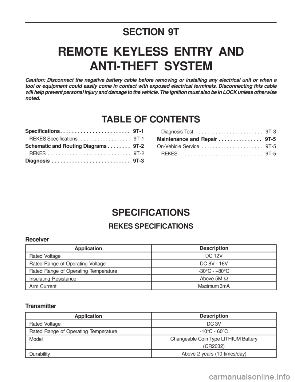
SPECIFICATIONS
REKES SPECIFICATIONS Diagnosis Test . . . . . . . . . . . . . . . . . . . . . . . .
9T-3
Maintenance and Repair . . . . . . . . . . . . . . . 9T-5
On-Vehicle Service . . . . . . . . . . . . . . . . . . . . . . 9T-5
REKES . . . . . . . . . . . . . . . . . . . . . . . . . . . . . . 9T-5
Transmitter
Description DC 3V
-10 °C - 60 °C
Changeable Coin Type LITHIUM Battery (CR2032)
Above 2 years (10 times/day)
Application
Rated Voltage
Rated Range of Operating Temperature Model Durability
Description DC 12V
DC 8V - 16V
-30 °C - +80 °C
Above 5M �
Maximum 3mA
Application
Rated Voltage
Rated Range of Operating Voltage
Rated Range of Operating Temperature Insulating Resistance Arm Current
Receiver
Page 1306 of 1574
9U-10 CONTROL UNITS AND SYSTEMMAINTENANCE AND REPAIR
ON-VEHICLE SERVICE
STICS STICS, electonic control warning device, controls 16 functions and contains the self diagnostic function detecting any malfunctions in the sensors and load. Removal & Installation Procedure
1. Disconnector the battery negative cable.
2. Unscrew 4screw from center console box.
3. Remove the center console box and disconnect 3 STICS connectors.
4. Unscrew 3 fastening bolts and remove the STICS unit.
5. Installation should follow the removal procedure in the reverse order.
1 STICS Unit
2 STICS Connector 3 STICS Unit Fastening Bolt
4 Parking Brake Lever
Page 1317 of 1574

MUSSO-SPORTS 1A-5
SUPPLEMENT
KAA5A020
KAA5A020
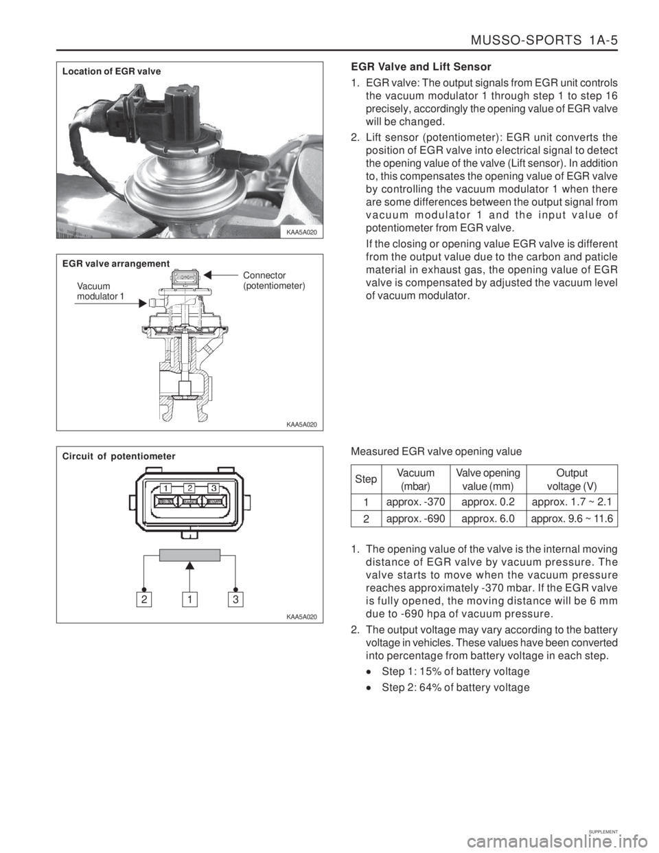
KAA5A020EGR Valve and Lift Sensor
1. EGR valve: The output signals from EGR unit controls
the vacuum modulator 1 through step 1 to step 16 precisely, accordingly the opening value of EGR valvewill be changed.
2. Lift sensor (potentiometer): EGR unit converts the position of EGR valve into electrical signal to detectthe opening value of the valve (Lift sensor). In additionto, this compensates the opening value of EGR valveby controlling the vacuum modulator 1 when thereare some differences between the output signal fromvacuum modulator 1 and the input value ofpotentiometer from EGR valve. If the closing or opening value EGR valve is different from the output value due to the carbon and paticlematerial in exhaust gas, the opening value of EGRvalve is compensated by adjusted the vacuum levelof vacuum modulator.
Measured EGR valve opening value Step 1 2
Vacuum(mbar)
approx. -370 approx. -690 Valve opening
value (mm)
approx. 0.2approx. 6.0 Output
voltage (V)
approx. 1.7 ~ 2.1
approx. 9.6 ~ 11.6
1. The opening value of the valve is the internal moving distance of EGR valve by vacuum pressure. The valve starts to move when the vacuum pressurereaches approximately -370 mbar. If the EGR valveis fully opened, the moving distance will be 6 mmdue to -690 hpa of vacuum pressure.
2. The output voltage may vary according to the battery voltage in vehicles. These values have been convertedinto percentage from battery voltage in each step.
Step 1: 15% of battery voltage
Step 2: 64% of battery voltage
Location of EGR valve EGR valve arrangement
Vacuum modulator 1 Connector (potentiometer)
Circuit of potentiometer
312
Page 1318 of 1574

1A-6 MUSSO-SPORTS
SUPPLEMENT
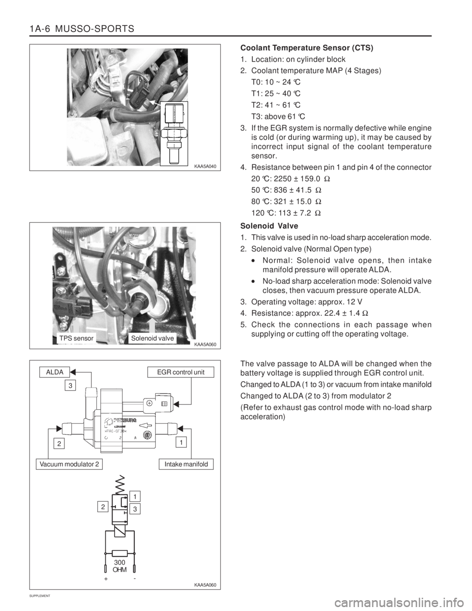
Coolant Temperature Sensor (CTS)
1. Location: on cylinder block
2. Coolant temperature MAP (4 Stages) T0: 10 ~ 24 °C
T1: 25 ~ 40 °C
T2: 41 ~ 61 °C
T3: above 61 °C
3. If the EGR system is normally defective while engine is cold (or during warming up), it may be caused by incorrect input signal of the coolant temperaturesensor.
4. Resistance between pin 1 and pin 4 of the connector 20 °C: 2250 ± 159.0 �
50 °C: 836 ± 41.5 �
80 °C: 321 ± 15.0 �
120 °C: 113 ± 7.2 �
KAA5A040 KAA5A060
KAA5A060Solenoid Valve
1. This valve is used in no-load sharp acceleration mode.
2. Solenoid valve (Normal Open type)
Normal: Solenoid valve opens, then intake
manifold pressure will operate ALDA.
No-load sharp acceleration mode: Solenoid valve
closes, then vacuum pressure operate ALDA.
3. Operating voltage: approx. 12 V
4. Resistance: approx. 22.4 ± 1.4 �
5. Check the connections in each passage when supplying or cutting off the operating voltage.
The valve passage to ALDA will be changed when the battery voltage is supplied through EGR control unit.
Changed to ALDA (1 to 3) or vacuum from intake manifold
Changed to ALDA (2 to 3) from modulator 2 (Refer to exhaust gas control mode with no-load sharp acceleration)
TPS sensorSolenoid valve
Intake manifold
ALDAEGR control unit
3
12
Vacuum modulator 2
2
1
3
300
OHM
+-
Page 1321 of 1574

MUSSO-SPORTS 1A-9
SUPPLEMENT
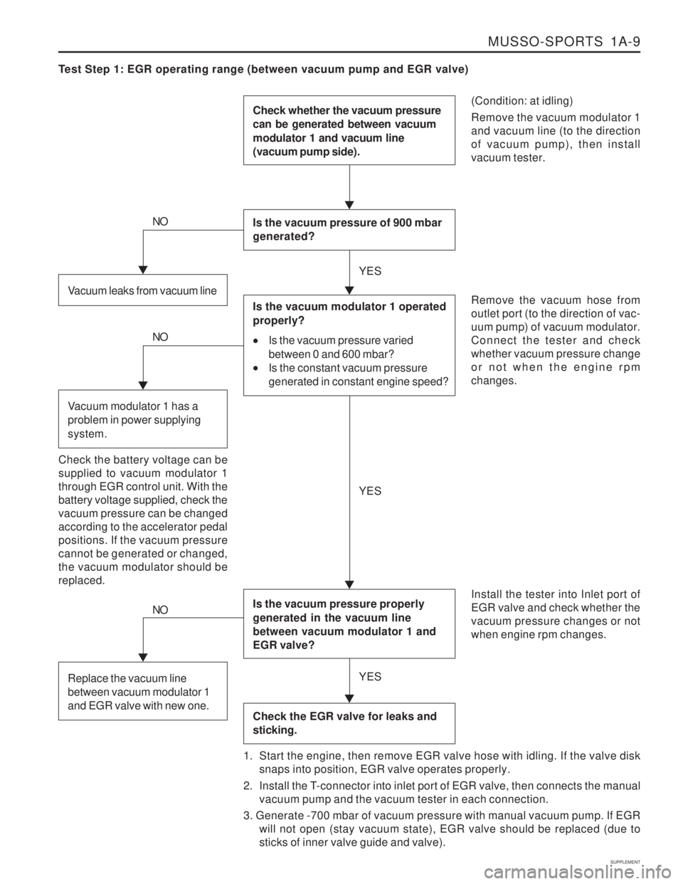
Test Step 1: EGR operating range (between vacuum pump and EGR valve)
(Condition: at idling) Remove the vacuum modulator 1 and vacuum line (to the directionof vacuum pump), then installvacuum tester.
Check whether the vacuum pressure can be generated between vacuum modulator 1 and vacuum line (vacuum pump side).
Is the vacuum pressure of 900 mbar generated?
Is the vacuum pressure properly generated in the vacuum line between vacuum modulator 1 and EGR valve?
Check the EGR valve for leaks and sticking.
Remove the vacuum hose from outlet port (to the direction of vac-uum pump) of vacuum modulator.Connect the tester and checkwhether vacuum pressure changeor not when the engine rpmchanges. Install the tester into Inlet port of EGR valve and check whether thevacuum pressure changes or notwhen engine rpm changes.
1. Start the engine, then remove EGR valve hose with idling. If the valve disk snaps into position, EGR valve operates properly.
2. Install the T-connector into inlet port of EGR valve, then connects the manual vacuum pump and the vacuum tester in each connection.
3. Generate -700 mbar of vacuum pressure with manual vacuum pump. If EGR will not open (stay vacuum state), EGR valve should be replaced (due tosticks of inner valve guide and valve).Vacuum leaks from vacuum line
NO
Is the vacuum modulator 1 operated properly?
Is the vacuum pressure varied
between 0 and 600 mbar?
Is the constant vacuum pressure
generated in constant engine speed?
Check the battery voltage can be supplied to vacuum modulator 1through EGR control unit. With thebattery voltage supplied, check thevacuum pressure can be changedaccording to the accelerator pedalpositions. If the vacuum pressurecannot be generated or changed,the vacuum modulator should bereplaced.
NO
Vacuum modulator 1 has a problem in power supplying system.
NO
Replace the vacuum line between vacuum modulator 1 and EGR valve with new one.
YES YES
YES